Advertisement
Advertisement
Table of Contents

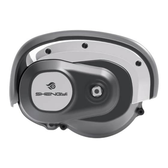
Summary of Contents for Shengyi CMT07
- Page 1 CMT07 Technical Instruction ~ - 1 - ~...
-
Page 2: Important Notice
Important Notice Please read this manual and the attached installation manual carefully. If you are not • clear about any part of the information in this manual, please do not install it. Please consult the sales office. For product information not described in this manual, please contact your dealer. •... -
Page 3: Main Technical Parameters
Intermediate drive unit. ★ It can meet the requirements of bicycle installation and is convenient to install; ★ The center drive unit has a highly modular design, which is convenient for motor maintenance; ★ The center drive unit has dual clutches; ★... - Page 4 2.1 Appearance 2.1.1 Instrument name Center intelligent liquid crystal instrument, model DM01B. Description of LCD display and key function. Full LCD image: Keys: ~ - 4 - ~...
-
Page 5: Parameter Setting
2.1.2 Parameter setting See product specification of DM01B. 2.2 Speed measuring sensor 2.2.1 Product model Model: SPL-10. 2.2.2 xterior (M5 cross slot pan head screw) (speed sensor) (shield) (induction magnetic steel) 2.2.3 Product installation drawing. 2.2.4 Specific specifications parameter numerical value rated voltage DC5V rated current... - Page 6 2.3 Chain wheel 2.3.1 Appearance of dental tray: (pictured) 2.3.2 Tooth plate type: 38T unilateral chain cover. 2.3.3 Basic parameters of dental tray. Number of teeth: 38 teeth Color: black. 2.4 Crank 2.4.1 Appearance of crank: (pictured) ~ - 6...
- Page 7 2.4.2 Basic parameters of crank: Length: 170mm Material: 6061 Color: Black. * Note: The screw thread directions of the left and right cranks are different, with "L" mark on the left crank and "R" mark on the right crank. ~ - 7 - ~...
- Page 8 Other Accessories Bracket Hexagon socket head bolts Hexagon socket head screws M6*63 M6*18 Decorative cover Hexagon socket head screws M4X8 Terminal box (for cover) (Locking torque: <1Nm) Cylinder head pattern screw M4x6 Chainwheel lock nut Crank Screw (Terminal box) (Locking torque:20-24Nm) (Locking torque:30-35Nm) (Locking torque:2.5-3Nm)...
-
Page 9: System Schematic Diagram
3.1.1 System schematic diagram. ~ - 8 - ~... -
Page 10: System Instruction
3.1.2 System instruction Matters needing attention and fault analysis. 4.1 matters need attention It should be parked in a ventilated and dry warehouse, and should not be parked in damp, acid and alkali places, nor should it coexist with magnetic articles; ~ - 9 - ~... -
Page 11: Packing List
Each connector is inserted in place according to the corresponding pair of arrows; The instrument avoids sharp objects from hitting; It is suggested that products should not be overloaded for a long time. Products should be protected from wading and flooding. 4.2 Routine fault analysis. - Page 12 Right crank 1PCS. Tray nut M35 (inverted teeth) 1PCS. Crank screw M8X20 (for installing crank) 2PCS. Pattern socket head cap screw M4X8 (for installing decorative cover) 3PCS. Pattern countersunk head socket M6X65 (used for connecting motor and frame connecting plate) 3PCS. Hexagon socket countersunk head screw M6X18 (used to connect the motor with the frame connecting plate) 3PCS.

Need help?
Do you have a question about the CMT07 and is the answer not in the manual?
Questions and answers