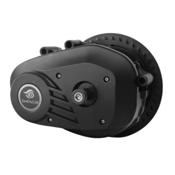
Summary of Contents for Shengyi CMT03E
- Page 1 CMT03E Product Technical Instruction (English) Product Name:Center-MotorAA Product Model:CMT03E(stand configuration) ~ - 1 - ~...
- Page 2 Important Notice •Please read the user manual and attached assembly manual. If you are not clear about any information in the manual, do not assembly and get help from Shengyi motor. • Any questions you can’t find the answer in the manual, please get contact with your dealer.
- Page 3 result in failure or rusted. • Using this product carefully, do not apply strong impact. • If you have any questions about the maintenance or how to use the product which unmentioned by the manual, please contact the retailer or dealer. •...
- Page 4 Content 1.Center motor 2.Accessory 3.Assemble way Notes and failure analysis 5. Packing list 6. Package ~ - 4 - ~...
- Page 5 1.Center motor It can meets the installation of bicycles and easy to install; ★ ★ It has a highly modular design for easy motor maintenance; Integration design makes it easy for customers to customize; ★ With dual clutch; ★ Controlled by torque, inside controller, speed limit 25KM/h; ★...
- Page 6 2.Acessory 2.1 Display 2.1.1 Display Name Center Intelligent LCD display,Model :APT12LCD760S。 ▪ LCD display instructions and button function description LCD whole drawing: Braking reminder Failure reminder Battery indicator Headlight indicator Speed mode Gear indicator Speed display Mileage mode Mileage indicator Button Function: 2.1.2 Parameter setting Pls check "Display 760S-J Protocol-4 Button Product Specification"...
- Page 7 2.2.2 Apperance (M5 PH screw) (speed sensor ) magnet) (cover) (Induction 2.2.3 Product Installation Drawing (Locking torque:<1Nm) 2.2.4 Specification Parameter value Rated Voltage DC5V Rated Current Pulse/circle Install distance 3-10mm Working Temp -30~70℃ Waterproof Grade IPX7 Certification CE ROHS ~ - 7 - ~...
- Page 8 2.3 Chain Wheel 2.3.1 Chain Wheel appearance: (as picture) 2.3.2 Chain Wheel Model: 42T single chain cover 2.3.3 Chain wheel basic parameter Teeths :42 T Shape:Concave with circular pattern Color:black 2.4 Crank 2.4.1 Crank Appearance : (as picture) 2.4.2 Crank Model: TS1-170AA 2.4.3 Crank basic parameter :...
- Page 9 2.5 Other accessory Connection Plate Hex Torx sunk socket Hex Torx sunk screw M6X65 M6X18 Left plastic housing Right plastic housing Hex Torx pan screw M4X8 Crank screw M8X20 External speed senor connection cable Chain Wheel nut M26(reverse tooth) Display connection cable Rear light connection cable Front light connection cable Power connection cable...
- Page 10 3.Assemble way 3.1System schematic diagram and connection diagram 3.1.1System schematic diagram ~ - 10 - ~...
- Page 11 3.1.2 System Connection Diagram (front of the bike) (back of the bike) ~ - 11 - ~...
- Page 12 3.2 Assemble Diagram 3.2.1 Threading Insert the external speed sensor connection cable , front light connection cable , display connection cable , rear light connection cable , power connection cable into the bike according to the requirements ; Insert all above cables into the motor according to ‘’ 3.1.2 system Connection diagram’’...
- Page 13 3.2.4 Install chain wheel ,locking the chain wheel screws Put the chain wheel on the motor in the direction of the spline slot; Screw the chain wheel nut (reverse-tooth) in the opposite direction(locking torque: 20-24Nm); 3.2.5 Install left and right cranks ,locking the cranks screws Put the crank on the middle shaft (the angle between the left and right cranks is 180°);...
- Page 14 Notes and failure analysis 4.1 Notes It should be store in a ventilated and dry warehouse, should not be stored in damp, acid and alkali, and should not put with magnetic goods; Each connector is inserted into the corresponding position by the arrow; The display LCD avoid colliding from sharp objects ;...
- Page 15 4.3 Other failure analysis and error codes See fault analysis 5. Packing list 1.Center motor 1 PC 2.Display 1 PC 3.Speed sensor (with magnet ) 1 PC 4.Chain wheel 1 SET 5.Left crank 1PCS 6.Right crank 1PCS 7.Left plastic housing 1PCS 8.Right plastic housing 1PCS...


Need help?
Do you have a question about the CMT03E and is the answer not in the manual?
Questions and answers