Advertisement
Quick Links
Installation Guide
1 General Information
1.1 Wireless alarm combined alerter «Trubach-К-RK» (hereinafter, the
Alerter) is designed for informing people about events and emergencies by
generating light and sound signals.
1.2 The Alerter is intended for operation as a component of a system that is
operated by a control panel (hereinafter, CP), supporting «Rielta-Contact-R»
wireless two-way data exchange protocol.
1.3 Wireless signal exchange with the CP is executed via of two-way
addressable radio communication within the 433.05 to 434.79 frequency
range. Two frequencies in are used for the radio exchange: the main
frequency and the reserve one. Turn-over to the reserve operating
frequency is fulfilled automatically in case of radio-frequency interference
on the main one.
1.4 Transmitter power does not exceed 10 mW.
1.5 The Alerter is powered by one lithium battery CR123A type with 3V
nominal voltage.
1.6 The Alerter generates and transmits via radio communication
the following messages:
- «Norm»;
- «Tamper» – after button «TEST» pushing;
- «Main power supply failure» – if power-supply voltage drops below
(2.5 ± 0.2) V ;
- «Backup power-supply low-battery» - if power-supply voltage drops
below (2.4 ± 0.2) V;
- «Identification» – together with switching identification;
- «Alerting ON» – if alert is switched ON.
1.7 The following rates of control radio exchange may be assigned
by the command from CP: 10 s, 15 s, 30 s, 60 s, 2 min, 5 min. Alarm
messages are transmitted immediately.
1.8 Alerter switching ON / OFF is executed by commands from the CP.
1.9 Alerter provides continuous and strobe light alert modes.
1.10 The Alerter provides light signal contrast at illumination level
up to 500 lk.
1.11 Strobe mode parameters can be set by user during the Alerter
adjustment.
1.12 Operation modes of the Alerter are displayed by two LED
indicators (see Table 3).
1.13 The Alerter ensures safe operation in standby mode being
powered from the built-in power supply battery up to 10 years or 6
hours of uninterrupted conjoined sound and light alerting.*
1.14 The Alerter is designed to operate continuously around the clock
in closed premises of residential and industrial buildings and structures.
1.15 The Alerter is resistant to the impact of electromagnetic
interference.
2 Principal Technical Characteristics
Table 1
Parameter
Acoustic pressure level at 1 m distance from
the sounder, not less than
Generated sound alarm signals frequency
Average consumption current in a standby
mode* , not more than
Average consumption current in a sound
alert mode, not more than
Average consumption current in a light alert
mode, not more than
Operating temperature
Permissible humidity at a temperature +40
°C
IP rating
Dimensions, not more than
Weight, not more than
Average service life
* – with a signal-monitoring interval of at least 60 s, radio interference absence
and normal operational conditions
WIRELESS ALARM
COMBINED ALERTER
«Trubach-К-RK»
Value
85 dBA
2 ... 5 kHz
15 mkA
90 mA
90 mA
minus 20 ... +55 °C
93 %
IP40
125х75х45 mm
0.25 kg
8 years
Standard direction pattern of the Alerter is shown in Figure 1.
30
о
60
о
90
о
Figure 1 – Direction Pattern
3 Scope of Delivery
Table 2
Name
Wireless alarm combined alerter «Trubach-К-RK»
Screw 3-3х40.016
Wall plug «SORMAT» NAT 5x25
Lithium power supply battery CR123A
Wireless alarm combined alerter «Trubach-К-RK».
Installation Guide
* Installed
4 Protective Measures
Dangerous voltages for human health are absent in the Alerter.
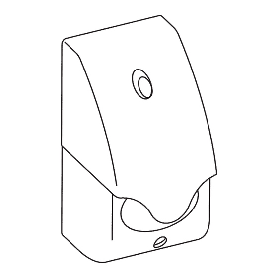
5 Design
The Alerter layout is shown in figure 2 and comprises the following
components:
- red diffusing filter (1);
- battery compartment cover (2);
- two wall mounting holes (3);
- base (4);
- «RESET» pin contacts (5);
- lithium battery and holder (6);
- radio communication quality checking button «TEST» (7);
- two runner slides for battery compartment cover (8);
- red and green LED indicators (9) under the diffusing filter.
3
2
1
Outside View
Figure 2 – Case of the Alerter
6 LED Indication
The Alerter displays its state by the LED indication as it shown in
Table 3.
Table 3
Operation Mode
Binding
Binding is finished
Identification
Alternate green and red indicators blinking
Communication
Quality
7 Switching On and Pre-starting Procedures
In general the operating procedure comprises the following steps:
- binding with the CP (logging in the CP);
- choosing place of installation and communication quality apprising;
- installation.
Attention! Board version 11 and higher does not support
MRF mode.
0
о
30
о
60
о
90
о
69
75
81
87
93
5 6
7
4
- +
8
9
3
with Removed Cover
LED Indication
Green LED intermittent blinking
Short-run (2 s) red LED lighting
See Table 4
dB
QNT.
1 pc.
2 pcs.
2 pcs.
1 pc.*
1 copy
Advertisement

Related Manuals for Rielta Trubach-K-RK


Summary of Contents for Rielta Trubach-K-RK
- Page 1 1.2 The Alerter is intended for operation as a component of a system that is Screw 3-3х40.016 2 pcs. operated by a control panel (hereinafter, CP), supporting «Rielta-Contact-R» Wall plug «SORMAT» NAT 5x25 2 pcs. wireless two-way data exchange protocol.
- Page 2 Rev. 3 of 14.06.2023 №00847 Made in Russia v10.1/v10.2/v11 «Development and Production Enterprise RIELTA» LLC Petrogradskaya nab., 34, letter B, Saint Petersburg, Russia, 197046 www.rielta.com, rielta@rielta.com Tel./fax: +7 (812) 233-0302, 703-1360, support@rielta.com Technical support, tel.: +7 (812) 233-29-53, 703-13-57, support@rielta.com...
Need help?
Do you have a question about the Trubach-K-RK and is the answer not in the manual?
Questions and answers