Advertisement
Quick Links
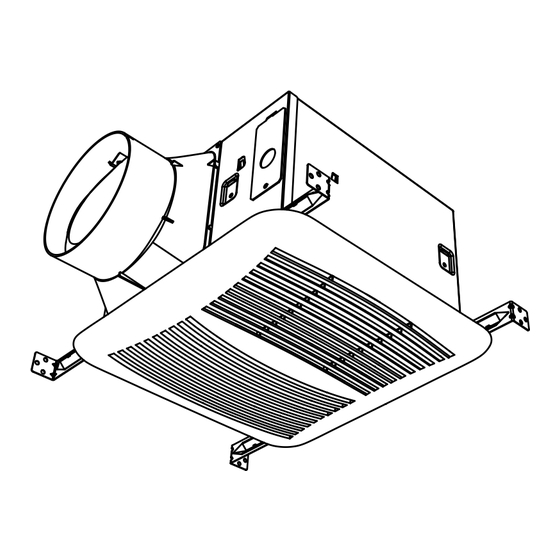
MODEL: SEPD140-3
SEPD140H-3
WARNING
TO REDUCE THE RISK OF FIRE, ELECTRIC SHOCK, OR INJURY TO PERSONS, OBSERVE THE FOLLOWING:
a). Use this unit only in the manner intended by the manufacturer. If you have questions, contact the
manufacturer.
b). Before servicing or cleaning unit, switch power off at service panel and lock the service discon-
necting means to prevent power from being switching on accidentally. When the service discon-
necting means cannot be locked, securely fasten a prominent warning device, such as a tag, to the
service panel.
c). Installation work and electrical wiring must be done by a qualified person(s) in accordance with all
applicable codes and standards, including fire-rated construction codes and standards.
d). Sufficient air is needed for proper combustion and exhausting of gases through the flue (chimney)
of fuel burning equipment to prevent backdrafting. Follow the heating equipment manufacturer's
guideline and safety standards such as those published by the National Fire Protection Association
(NFPA), and the American Society for Heating, Refrigeration and Air Conditioning Engineers
(ASHRAE), and the local code authorities.
e). When cutting or drilling into wall or ceiling, do not damage electrical wiring and other hidden
utilities.
f ). Ducted fans must always be vented to the outdoors.
g). Acceptable for use over a tub or shower when connected to a GFCI (Ground Fault Circuit Inter-
rupter) - protected branch circuit (ceiling installation only).
h). This unit must be grounded.
i). Not for Use in Kitchens.
j). To reduce risk of fire and to properly exhaust air, be sure to duct air outside - Do not vent exhaust
air into spaces within walls or ceilings or into attics, crawl spaces, or garages.
k). WARNING: To Reduce The Risk Of Fire Or Electric Shock, Do Not Use This Fan With Any
Solid-State Speed Control Device.
l). The fan must not be installed in a ceiling thermally insulated to a value greater than R40.
CAUTION
1. For general ventilating use only. Do not use to exhaust hazardous or explosive materials and vapors.
2. This product is designed for installation in ceilings up to a 12/12 pitch (45 degree angle). Duct connector must point up.
DO NOT MOUNT THIS PRODUCT IN A WALL.
3. To avoid motor bearing damage and noisy and/or unbalanced impellers, keep drywall spray, construction dust, etc. off power unit.
4. Please read specification label on product for further information and requirements.
CLEANING & MAINTENANCE
For quiet and efficient operation, long life, and attractive appearance - lower or remove grille and vacuum interior of unit with the dusting brush attach-
ment.The motor is permanently lubricated and never needs oiling. If the motor bearings are making excessive or unusual noises, replace the motor with
the exact service motor. The impeller should also be replaced.
Installer: Leave this manual with the homeowner.
READ AND SAVE THESE INSTRUCTIONS
VENTILATION FAN
Advertisement

Related Manuals for STERLING FANS SEPD140-3


Summary of Contents for STERLING FANS SEPD140-3
- Page 1 VENTILATION FAN MODEL: SEPD140-3 SEPD140H-3 WARNING TO REDUCE THE RISK OF FIRE, ELECTRIC SHOCK, OR INJURY TO PERSONS, OBSERVE THE FOLLOWING: a). Use this unit only in the manner intended by the manufacturer. If you have questions, contact the manufacturer.
- Page 2 OPERATION See “ELECTRICAL WIRING” for wiring and switch details. The control box, located inside the fan housing, has four settings: (1) the low airflow knob adjusts the lower airflow from 30 CFM up to the air flow rate of the high fan speed determined by the toggle switch setting.
- Page 3 ASSEMBLY INSTRUCTIONS 1. Sliding hanger bars have been provided, which allow the housing to be positioned accurately anywhere between the framing. The Hanger Bar bars span up to 24 in. and can be used on all types of framing: I-joist, standard joist, and truss construction. Slide hanger bars onto housing and adjust as needed to fit between framing.
- Page 4 INSTALL GRILLE Install ceiling material to complete the ceiling construction. Then, cut around the fan housing. Insert the plug from the sensor system into the power box. To attach the grille assembly to the fan housing. Pinch the grille springs on the sides of the grille assembly, and position the grille into the housing with the grille springs in the appropriate slots.
Need help?
Do you have a question about the SEPD140-3 and is the answer not in the manual?
Questions and answers