Table of Contents
Advertisement
Quick Links
INSTRUCTION HANDBOOK
Electric Stackers
PS E12BM / PS E12NM
WARNING
Do not use the electric truck before reading
and understanding these operating
instructions.
NOTE:
• Please check the designation of your
present type at the last page of this
document as well as on the ID-plate.
• Keep for future reference.
Version 03/2023
PSE12BM/PSE12NM-SMS-002-EN
xyz
Advertisement
Table of Contents

Related Manuals for Noblelift PS E12BM


Summary of Contents for Noblelift PS E12BM
- Page 1 INSTRUCTION HANDBOOK Electric Stackers PS E12BM / PS E12NM WARNING Do not use the electric truck before reading and understanding these operating instructions. NOTE: • Please check the designation of your present type at the last page of this Version 03/2023 document as well as on the ID-plate.
- Page 2 FOREWARD Before operating the electric stacker, read this ORIGINAL INSTRUCTION HANDBOOK carefully and understand the usage of the truck completely. Improper operation of the truck may create a danger situation. This handbook describes the usage of different electric stackers. When operating and servicing the truck, make sure, that it applies to your type.
-
Page 3: Table Of Contents
TABLE OF CONTENTS CORRECT APPLICATION ......................... 4 DESCRIPTION OF THE STACKER ....................5 Overview of the main components ....................5 Main technical data ......................... 6 Description of the safety devices and warning labels (Europe and other, except USA) ....8 Identification plate ........................... - Page 4 Battery Indicator ..........................21 Charging ............................22 REGULAR MAINTENANCE ......................23 Maintenance checklist........................23 Lubricating points .......................... 24 Check and refill hydraulic oil ......................24 Checking electrical fuses ......................25 Removing, reattaching guarding ....................25 10. TROUBLE SHOOTING ........................26 11.
-
Page 5: Correct Application
1. CORRECT APPLICATION It is only allowed to use this electric stacker according to this instruction handbook. The trucks described in this handbook are self-propelled pedestrian controlled electric power stackers, with electrically powered lifting function. The trucks are designed for stacking operations in dedicated racking by lifting and lowering the palletized loads up to the desired lifting heights. -
Page 6: Description Of The Stacker
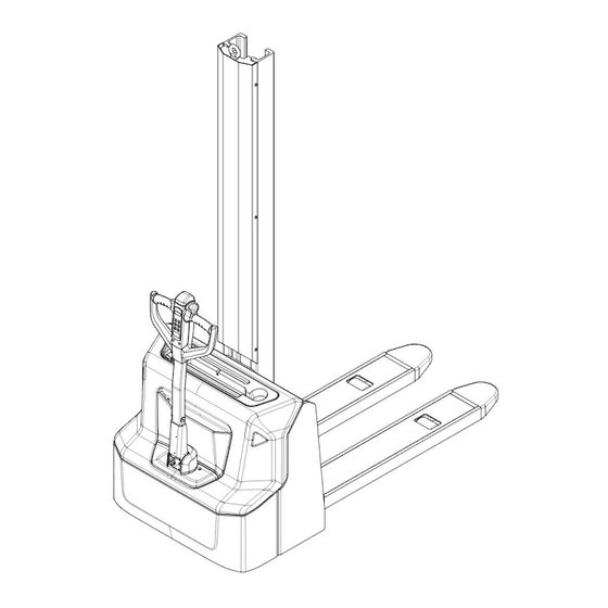
2. DESCRIPTION OF THE STACKER a. Overview of the main components Fig. 1: Overview main components Mast 10. Main cover 19. Spring cord Fork carriage 11. Cover 20. Charging LED Load roller assembly 12. Cover 21. Panel Chassis 13. Protective board 22. -
Page 7: Main Technical Data
b. Main technical data Fig. 2: Technical data... - Page 8 Table1: Main technical data for standard version Type sheet for industrial truck acc. to VDI 2198 PS E12BM PS E12NM Manufacturer`s type designation Battery Power (battery ,diesel, petrol, gas, manual) Operator type Pedestrian Q(t) Load Capacity / rated load c(mm)
-
Page 9: Description Of The Safety Devices And Warning Labels (Europe And Other, Except Usa)
Battery acc. to DIN 43531/35/36 A, B, C, Battery voltage, nominal capacity K5 V/Ah 2 x 12 / 85 24 / 60 2 x 27 Battery weight Kwh/h Energy consumption acc: to VDI cycle Type of drive control Sound level at driver’s ear acc. to EN 12053 dB(A) <70 1) Stacker with eye-bolt: +55mm。... -
Page 10: Identification Plate
d. Identification plate Designation, type Battery weight minimum/ maximum Serial number Nominal power in kW Rated capacity in kg Load center distance Supply voltage in V 10 Manufacturing date Own mass (self weight) in kg without battery 11 Option Name and address of manufacturer) If sold to the EU, here the place of the CE marking Fig. -
Page 11: Warnings, Residual Risk And Safety Instructions
3. WARNINGS, RESIDUAL RISK AND SAFETY INSTRUCTIONS DO NOT • Put foot or hand under or into the lifting mechanism. • Allow other person than the operator to stand in front of or behind the truck when it is moving or lifting/lowering. •... -
Page 12: Commissioning, Transporting, Decommissioning
4. COMMISSIONING, TRANSPORTING, DECOMMISSIONING a. Commissioning Table 2: Commissioning data Type PS E12BM/ 2000 PS E12NM/ 2000 Commissioning weight [kg] Dimensions 2000 2000 [mm] After receiving our new stacker or for re-commissioning you have to do following before (firstly) operating the truck: •... -
Page 13: Decommissioning
Transportation DURING TRANSPORTATION ON A LORRY OR TRUCK ALWAYS FASTEN THE TRUCK SECURELY Lower the forks and park the truck securely. Fasten the truck according to Fig. 6 by fixing dedicated lashing belts to chassis, Fork carriage and mast, and fasten the other side at the transporting truck. c. -
Page 14: Daily Inspection
5. DAILY INSPECTION This chapter describes pre-shift checks before putting the truck into operation. Daily inspection is effective to find the malfunction or fault on this truck. Check the truck on the following points before operation. Remove load from truck and lower the forks. DO NOT USE THE TRUCK IF ANY MALFUNCTION IS FOUND. -
Page 15: Operation Instructions
SAFETY INSTRUCTIONS (CHAPTER 3). Make sure, that the load is palletized and stable and that the daily inspection is carried out. PS E12BM Pull out the emergency button (Fig.1, 18), type the password on pin-code panel and press √ button to start the truck. -
Page 16: Lifting
The white markings on the mast indicate if the specific lifting limits reached. For instance with a load centre of gravity distance c of 600 mm and a maximum lift height H of 2000 mm, the max. Capacity Q is 1200 kg. -
Page 17: Steering
After starting the truck by activation from Pin-code panel carefully move the tiller to the operating zone (‘F’, fig.11). Turn the accelerator button to the desired direction forward ‘Fw.’ Or backwards ‘Bw.’(fig. 11). Control the travelling speed by moving the accelerator button (22) carefully until you reached the desired speed. -
Page 18: Malfunctions
h. Malfunctions If there are any malfunctions or the truck is inoperative, please stop using the truck and activate the emergency button (18) by pushing it. If possible, park the truck on a safe area and press the X button of pin-code panel. -
Page 19: Pin-Code Panel
For PS E12NM, it can be operated only when correct password is typed or valid ID card is used. PS E12BM supports password access and supports 1 set of password. The password consists of 4 numbers ranging from 0 to 9. -
Page 20: Battery Safety, Charging And Replacement
Only qualified personnel are allowed to service or charge the batteries. The instructions of this handbook must be observed. • PS E12BM is lead acid battery, PS E12NM is lithium battery • Recycling of batteries undergoes national regulations. Please follow these regulations. -
Page 21: Matters Requiring Attention (Lithium Battery)
Installation environment In order to ensure the best operating performance, the battery need to be kept under normal working conditions: between 0 and 40 degrees Celsius and normal humidity. Avoid excessive temperature difference on both sides of the battery (more than 5℃) Emergency management Below are examples of several ways to deal with possible emergencies: •... -
Page 22: Replacement
Thirdly, unloosen and remove the battery fixing frame. For PS E12BM, remove the second battery on bottom following the same way of disassembly of the first battery. The installation is in the reverse order. -
Page 23: Charging
It is normally off, when it appears (fixed) it shows the request of programmed maintenance or the alarm state. In this case the relative code will be displayed. The information supplied by the MDI-CAN can be extremely useful. Failures can be quickly identified by the operator or service technician thereby finding the fastest solution to the problem. -
Page 24: Regular Maintenance
9. REGULAR MAINTENANCE • Only qualified and trained personnel are allowed to do maintenance on this truck. • Before maintaining, remove the load and lower the forks to the lowest position. • If you need to lift the truck, follow chapter 4 b by using designated lashing or jacking equipment. -
Page 25: Lubricating Points
• 18 Test the Emergency switch function • 19 Check the electric drive motor for noise and damages • 20 Test the display • 21 Check if correct fuses are used, if necessary replace. • 22 Test the audio warning signal •... -
Page 26: Checking Electrical Fuses
d. Checking electrical fuses Fig. 15: Location of fuses Table 5: Size of the fuses Rate 150A FU01 FU02 (PS E12N) 1.5A e. Removing, reattaching guarding DO NOT USE THIS TRUCK, IF THE GUARDING IS DAMAGED OR NOT CORRECTLY ASSEMBLED! If the guarding needs to be removed - de-attach holding clamps carefully. -
Page 27: Trouble Shooting
TROUBLE SHOOTING If the truck has malfunctions follow the instructions, mentioned in chapter 6. Table 6: Trouble shooting TROUBLE CAUSE REPAIR Lift only the max. capacity, Load weight too high mentioned on the ID-plate Battery discharged Charge the battery Check and eventually replace Load can’t be Lifting fuse faulty the lifting fuse... -
Page 28: Wiring/ Circuit Diagram
11. WIRING/ CIRCUIT DIAGRAM Electrical circuit diagram FU1 : 60 A FU2 : 150 A FU01 : 10 A Fig. 16: Electrical diagram manual steering PS E12BM... - Page 29 FU1 : 60 A FU2 : 150 A FU01 : 10 A FU02 : 1.5 A Fig. 17: Electrical diagram manual steering PS E12NM...
-
Page 30: Electrical Circuit Diagram (En1175:2020)
Electrical circuit diagram (EN1175:2020) FU1 : 60 A FU2 : 150 A FU01 : 10 A Fig. 18: Electrical diagram manual steering PS E12BM (EN1175:2020) - Page 31 FU1 : 60 A FU2 : 150 A FU01 : 10 A FU02 : 1.5 A Fig. 19: Electrical diagram manual steering PS E12NM (EN1175:2020)
-
Page 32: Hydraulic Circuit
Table 7: Description of electrical diagram Code Item Code Item Code Item Tiller Driving motor Button switch Controller Inter-lock switch Charger Fuse Lifting limit switch USB port battery Sensor of speed reduction on curve Brake Horn DC power switch Lowering valve Contactor Limit switch Pump motor... -
Page 33: Schematic Diagram Of Braking System
Schematic diagram of braking system Fig. 21: Braking schematic diagram... -
Page 34: Declaration Of Conformity (Valid, If Sold Within The Eu)
CE-DD-002 12. DECLARATION OF CONFORMITY (valid, if sold within the EU) [GB] CE Declaration of Conformity The signatory hereby declares that the specified machine conforms to the EU Directive 2006/42/EC (Machine Directive) and 2014/30/EU (Electro-Magnetic Compatibility, EMC) including their amendments as translated into national legislation of the member countries. The signatory is individually authorized to compile the technical documents. - Page 35 nacionālajai likumdošanai. Parakstu īpašnieki ir atsevišķi pilnvaroti sastādīt tehniskās dokumentācijas. [N] EU-KONFORMITETSERKLÆ RING Undertegnede bekrefter hermed at de enkelte betegnede maskin med kraftdrift tilsvarer de europeiske retningslinjene 2006/42/EC (maskinretningslinje) og 2014/30/EU (elektromagnetisk fordraglighet - EMV) inklusiv disses endringer og den tilsvarende rettsforordning til omsetning av nasjonal rett. Hver undertegnede er fullmektig til å...
Need help?
Do you have a question about the PS E12BM and is the answer not in the manual?
Questions and answers