Table of Contents
Advertisement
INSTRUCTION HANDBOOK
Electric Stacker ECL15B
WARNING
Do not use the electric truck before reading
and understanding these operating
instructions.
NOTE:
• Please check the designation of your
present type at the last page of this
document as well as on the ID-plate.
• Keep for future reference.
Version 11/2019
ECL15B-SMS-001-EN
xyz
Advertisement
Table of Contents

Related Manuals for Noblelift ECL15B Series


Summary of Contents for Noblelift ECL15B Series
- Page 1 INSTRUCTION HANDBOOK Electric Stacker ECL15B WARNING Do not use the electric truck before reading and understanding these operating instructions. NOTE: • Please check the designation of your present type at the last page of this Version 11/2019 document as well as on the ID-plate. •...
- Page 2 FORWARD Before operating the electric stacker, read this ORIGINAL INSTRUCTION HANDBOOK carefully and understand the usage of the truck completely. Improper operation of the truck may create a danger situation. This handbook describes the usage of different electric stackers. When operating and servicing the truck, make sure, that it applies to your type.
-
Page 3: Table Of Contents
TABLE OF CONTENTS CORRECT APPLICATION ......................... 4 DESCRIPTION OF THE STACKER ....................5 Overview of the main components ....................5 Main technical data ......................... 6 Description of the safety devices and warning labels (Europe and other, except USA) ....7 Identification plate ........................... - Page 4 TROUBLE SHOOTING ........................22 10. WIRING/ CIRCUIT DIAGRAM ......................23 Electrical circuit diagram ....................... 23 Hydraulic circuit ..........................24 11. DECLARATION OF CONFORMITY (valid, if sold within the EU) ............ 25...
-
Page 5: Correct Application
1. CORRECT APPLICATION It is only allowed to use this electric stacker according to this instruction handbook. The trucks described in this handbook are self-propelled pedestrian controlled electric power stackers, with electrically powered lifting function. The trucks are designed for stacking operations in dedicated racking by lifting and lowering the palletized loads up to the desired lifting heights. -
Page 6: Description Of The Stacker
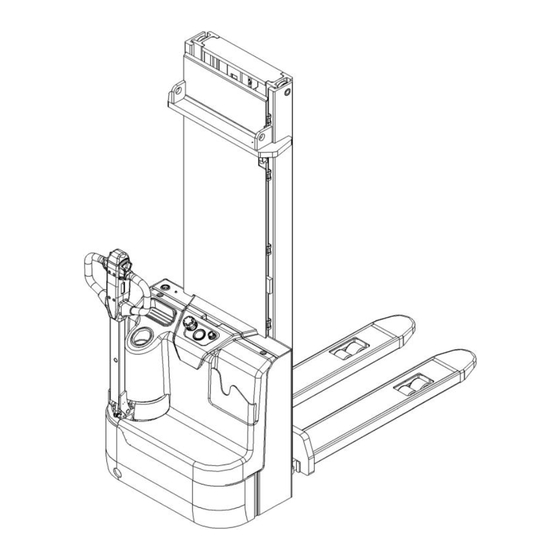
2. DESCRIPTION OF THE STACKER a. Overview of the main components Fig. 1: Overview main components Motor cover 10. Main cover Driving wheel 11. Discharge indicator and charging indicating Steering wheel Charging LED 12. Key switch Charging cable 13. Chassis Emergency button 14. -
Page 7: Main Technical Data
b. Main technical data Table1: Main technical data for standard version Fig. 2: Technical data Type sheet for industrial truck acc. to VDI 2198 ECL15B Manufacturer`s type designation 1600 3600 Battery Power (battery ,diesel, petrol, gas, manual) Pedestrian Operator type Q(t) Load Capacity / rated load C(mm) -
Page 8: Description Of The Safety Devices And Warning Labels (Europe And Other, Except Usa)
4.22 Fork dimensions s/ e/ l(mm) 60/180/1150 4.25 Width across forks (mm) 570/685 4.32 m2(mm) Ground clearance, centre of wheelbase 4.33 Ast (mm) 2293 2317 Aisle width for pallets 1000X1200 crossways 4.34 Aisle width for pallets 800X1200 lengthways Ast (mm) 2237 2261 4.35... - Page 9 tiller is in its operating zone. Follow also the instructions given on the decals. Replace the decals if they are damaged or missing. d. Identification plate Designation, type Battery weight minimum/ maximum Serial number Nominal power in kW Rated capacity in kg Load center distance Supply voltage in V 10 Manufacturing date...
-
Page 10: Warnings, Residual Risk And Safety Instructions
3. WARNINGS, RESIDUAL RISK AND SAFETY INSTRUCTIONS DO NOT • Put foot or hand under or into the lifting mechanism. • Allow other person than the operator to stand in front of or behind the truck when it is moving or lifting/lowering. •... -
Page 11: Commissioning, Transporting, Decommissioning
4. COMMISSIONING, TRANSPORTING, DECOMMISSIONING a. Commissioning Table 2: Commissioning data Type ECL15B/1600 ECL15B/3600 Commissioning weight [kg] Dimensions [mm] 1600 3600 After receiving our new stacker or for re-commissioning you have to do following before (firstly) operating the truck: • Check if are all parts included and not damaged •... -
Page 12: Decommissioning
Transportation DURING TRANSPORTATION ON A LORRY OR TRUCK ALWAYS FASTEN THE TRUCK SECURELY Lower the forks and park the truck securely. Fasten the truck according to Fig. 6 by fixing dedicated lashing belts to chassis, Fork carriage and mast, and fasten the other side at the transporting truck. c. -
Page 13: Operation Instructions
6. OPERATION INSTRUCTIONS BEFORE OPERATING THIS TRUCK, PLEASE FOLLOW WARNINGS SAFETY INSTRUCTIONS (CHAPTER 3). BEFORE OPERATING THIS TRUCK, ENSURE THAT THE LOAD OR OTHER EQUIPMENT NOT CAUSES INSUFFICIENT VISIBILITY! Make sure that the load is palletized and stable and that the daily inspection is carried out. -
Page 14: Lifting
c. Lifting DO NOT OVERLOAD THE TRUCK! THE MAXIMUM CAPACITY IS 1500kg. LIFT ONLY CAPACITIES ACCORDING TO THE RESIDUAL LIFT DIAGRAM. Travel with the lowered forks fully underneath the pallet and press the lifting button (Fig. 7, 22) until you reached the desired lifting height. -
Page 15: Steering
Control the travelling speed by moving the accelerator button (13) carefully until you reached the desired speed. If you move the accelerator button back to the neutral position, the controller decelerates the truck until the truck stops. If the truck stopped, the parking brake will be engaged. Drive carefully the truck to the destination. -
Page 16: Battery Charging And Replacement
7. BATTERY CHARGING AND REPLACEMENT • Only qualified personnel are allowed to service or charge the batteries. The instructions of this handbook and from the battery- manufacturer must be observed. • The batteries are maintenance free batteries. • Recycling of batteries undergoes national regulations. Please follow these regulations. -
Page 17: Battery Indicator
b. Battery Indicator Fig. 13: Battery discharge indicator When battery is fully charged, it shows 100% It is normally off, when it appears (fixed) it shows the request of programmed maintenance or the alarm state. “FC” means fault code, it’s normal off, when it appears, it shows there is failure of truck, and the exact fault code will show after it. -
Page 18: Charging
c. Charging • Before using the charger, please fully understand the instructions of the charger instructions. • Always follow these instructions. • The room, where you are charging must be ventilated. • The exactly charge status can be only checked from the discharge indicator. To control the status, the charging must be interrupted and the truck must be started. -
Page 19: Regular Maintenance
8. REGULAR MAINTENANCE • Only qualified and trained personnel are allowed to do maintenance on this truck. • Before maintaining, remove the load and lower the forks to the lowest position. • If you need to lift the truck, follow chapter 4b by using designated lashing or jacking equipment. -
Page 20: Lubricating Points
• 21 Check if correct fuses are used, if necessary replace. • 22 Test the audio warning signal • 23 Check the contactors • 24 Check the frame leakage (insulation test) • 25 Check function and wear of the accelerator •... -
Page 21: Checking Electrical Fuses
d. Checking electrical fuses Fig. 17: Location of fuses Table 5: Size of the fuses Rate 0.5A FU 01 FU 02 130A e. Removing, reattaching guarding DO NOT USE THIS TRUCK, IF THE GUARDING IS DAMAGED OR NOT CORRECTLY ASSEMBLED! If the guarding needs to be removed, unscrew carefully. -
Page 22: Trouble Shooting
9. TROUBLE SHOOTING • If the truck has malfunctions follow the instructions, mentioned in chapter 6. Table 6: Trouble shooting TROUBLE CAUSE REPAIR Lift only the max. capacity, Load weight too high mentioned on the ID-plate Battery discharged Charge the battery Check and eventually replace Load can’t be Lifting fuse faulty... -
Page 23: Wiring/ Circuit Diagram
10. WIRING/ CIRCUIT DIAGRAM a. Electrical circuit diagram Fig. 18: Electrical diagram... -
Page 24: Hydraulic Circuit
Table 7: Description of electrical diagram Code Item Code Item Battery FU01 80A fuse Controller Horn Pump motor FU02 130A fuse Pump contactor S1 S2 S3 S4 Tiller micro switch Emergency button Key switch Electromagnetic valve 48V charger Micro switch Charging cable CAN accelerator 0.5A fuse... -
Page 25: Declaration Of Conformity (Valid, If Sold Within The Eu)
CE-DD-002 11. DECLARATION OF CONFORMITY (valid, if sold within the EU) [GB] CE Declaration of Conformity The signatory hereby declares that the specified machine conforms to the EU Directive 2006/42/EC (Machine Directive) and 2014/30/EU (Electro-Magnetic Compatibility, EMC) including their amendments as translated into national legislation of the member countries. The signatory is individually authorized to compile the technical documents. - Page 26 nacionālajai likumdošanai. Parakstu īpašnieki ir atsevišķi pilnvaroti sastādīt tehniskās dokumentācijas. [N] EU-KONFORMITETSERKLÆRING Undertegnede bekrefter hermed at de enkelte betegnede maskin med kraftdrift tilsvarer de europeiske retningslinjene 2006/42/EC (maskinretningslinje) og 2014/30/EU (elektromagnetisk fordraglighet - EMV) inklusiv disses endringer og den tilsvarende rettsforordning til omsetning av nasjonal rett. Hver undertegnede er fullmektig til å...
Need help?
Do you have a question about the ECL15B Series and is the answer not in the manual?
Questions and answers