Table of Contents
Advertisement
Quick Links
Advertisement
Chapters
Table of Contents

Subscribe to Our Youtube Channel
Related Manuals for Panasonic Lumix DMC-TZ50P


Summary of Contents for Panasonic Lumix DMC-TZ50P
- Page 1 ORDER NO.DSC0805030CE Digital Camera DMC-TZ50P Model No. VOL.1 Product Colour (S)....Silver Type © 2008 Matsushita Electric Industrial Co., Ltd. All rights reserved. Unauthorized copying and distribu- tion is a violation of law.
-
Page 2: Table Of Contents
TABLE OF CONTENTS PAGE PAGE 1 Safety Precautions -----------------------------------------------3 1.1. General Guidelines ----------------------------------------3 1.2. Leakage Current Cold Check ---------------------------3 1.3. Leakage Current Hot Check (See Figure 1)---------3 1.4. How to Discharge the Capacitor on Flash PCB------------------------------------------------------------4 1.5. Handling of Wi-Fi Module --------------------------------4 2 Warning --------------------------------------------------------------5 2.1. -
Page 3: Safety Precautions
1 Safety Precautions 1.1. General Guidelines 1.3. Leakage Current Hot Check 1. IMPORTANT SAFETY NOTICE (See Figure 1) There are special components used in this equipment 1. Plug the AC cord directly into the AC outlet. Do not use which are important for safety. These parts are marked by an isolation transformer for this check. -
Page 4: How To Discharge The Capacitor On Flash Pcb
1.4. How to Discharge the Capacitor on Flash PCB CAUTION: 1. Be sure to discharge the capacitor on FLASH PCB. 2. Be careful of the high voltage circuit on FLASH PCB when servicing. [Discharging Procedure] 1. Refer to the disassemble procedure and remove the necessary parts/unit. 2. -
Page 5: Warning
2 Warning 2.1. Prevention of Electrostatic Discharge (ESD) to Electrostatic Sensitive (ES) Devices Some semiconductor (solid state) devices can be damaged easily by static electricity. Such components commonly are called Elec- trostatically Sensitive (ES) Devices. The following techniques should be used to help reduce the incidence of component damage caused by electrostatic discharge (ESD). -
Page 6: Fcc Rf Exposure Statement
2.3. FCC RF Exposure Statement... -
Page 7: Important Notice
2.4. Important Notice... -
Page 9: How To Replace The Lithium Battery
2.5. How to Replace the Lithium Battery 2.5.1. Replacement Procedure 1. Remove the Top Operation PCB. (Refer to Disassembly Procedures.) 2. Remove the Lithium battery (Ref. No. at component side of Top Operation PCB) and then replace it into new one. Note: The lithium battery is a critical component. -
Page 10: Service Navigation
3 Service Navigation 3.1. Introduction This service manual contains technical information, which will allow service personnel's to understand and service this model. Please place orders using the parts list and not the drawing reference numbers. If the circuit is changed or modified, the information will be followed by service manual to be controlled with original service manual. 3.2. -
Page 11: How To Define The Model Suffix
3.4. How to Define the Model Suffix There are two kinds of DMC-TZ50, regardless of the colour. • a) DMC-TZ50 (Japan domestic model.) • b) DMC-TZ50P (DMC-TZ50S is exclusively Japan domestic model.) What is the difference is that the “INITIAL SETTINGS” data which is stored in Flash ROM mounted on Main PCB. 3.4.1. - Page 12 3.4.2. INITIAL SETTINGS: When you replace the Main PCB, be sure to perform the initial settings after achieving the adjustment by ordering the following pro- cedure in accordance with model suffix of the unit. 1. IMPORTANT NOTICE: Before proceeding Initial settings, be sure to read the following CAUTIONS. 2.
- Page 13 • Step 5. Set the INITIAL SETTING: (Refer to “CAUTION 1”) [Caution for before settings] Once “NONE(JAPAN)” (Area for japan) is selected with “INITIAL SETTINGS”, other area will not displayed even if “INITIAL SET- TINGS” menu is displayed again, thus, the area can not be changed. Select the area carefully.
-
Page 14: Specifications
4 Specifications... -
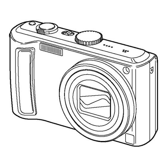
Page 16: Location Of Controls And Components
5 Location of Controls and Components... -
Page 18: Operating Instructions
6 Installation Instructions 6.1. Wi-Fi Function General Description... -
Page 20: Inspection Procedure (Flowchart)
6.2. Inspection procedure (Flowchart) • See the following inspection procedure for Wi-Fi connection trouble. -
Page 21: Personnel Information
6.3. Personnel Information: Since this unit is equipped with Wi-Fi function, the confidential user's personal information (such as ID, password, mail address) is kept in the unit. Although we requested to user "delete personal information when requesting repair", handle it as strictly confidential when it is still remained. -
Page 27: Service Mode
7 Service Mode 7.1. Error Code Memory Function 1. General description This unit is equipped with history of error code memory function, and can be memorized 16 error codes in sequence from the latest. When the error is occurred more than 16, the oldest error is overwritten in sequence. The error code is not memorized when the power supply is shut down forcibly (when the unit is powered on by the battery, the battery is pulled out) because the error code is memorized to FLASH ROM when the unit is powered off. - Page 28 Attribute Main item Sub item Error code Contents (Upper) High 4bits Low 4 bits Check point (Lower) LENS Lens drive 18*0 1000 PSD (X) error. Hall element (X axis) position detect error in OIS unit. OIS Unit 2000 PSD (Y) error. Hall element (Y axis) position detect error in OIS unit. OIS Unit 3000 GYRO (X) error.
- Page 29 Attribute Main item Sub item Error code Contents (Upper) High 4bits Low 4 bits Check point (Lower) SOFT Reset 30*0 0001 NMI reset Non Mask-able Interrupt 0007 (30000001-30000007 are caused by factors) Card Card 31*0 0001 Card logic error SD memory card data line or IC6001 (VENUS 4) 0002 Card physical error SD memory card data line or IC6001 (VENUS 4)
-
Page 30: Service Fixture & Tools
8 Service Fixture & Tools 8.1. Service Fixture and Tools The following Service Fixture and tools are used for checking and servicing this unit. 8.2. When Replacing the Main PCB After replacing the MAIN PCB, be sure to achieve adjustment. The adjustment instruction is available at “software download”... - Page 31 8.3.1. Extension Cable Connections CAUTION-1. (When servicing FLASH PCB) 1. Be sure to discharge the capacitor on FLASH PCB. Refer to “HOW TO DISCHARGE THE CAPACITOR ON FLASH PCB”. The capacitor voltage is not lowered soon even if the AC Cord is unplugged or the battery is removed. 2.
-
Page 32: Disassembly And Assembly Instructions
9 Disassembly and Assembly Instructions 9.1. Disassembly Flow Chart 9.2. PCB Location... -
Page 33: Disassembly Procedure
9.3. Disassembly Procedure 9.3.1. Removal of the Rear Case Unit Item Fig. Removal Rear Case Unit Fig. D1 Card Battery 2 Screws (A) 1 Screw (B) 2 Screws (C) FP9004 (Flex) FP9007 (Flex) Rear Case Unit LCD Unit Fig. D2 5 Locking tabs LCD Unit Main P.C.B. - Page 34 9.3.2. Removal of the LCD Unit 9.3.3. Removal of the Main P.C.B. Fig. D2 Fig. D3...
- Page 35 9.3.4. Removal Top Operation Unit 9.3.5. Removal of the Top Operation P.C.B. Fig. D4 Fig. D5...
- Page 36 9.3.6. Removal of the Sub P.C.B. Fig. D6 Fig. D7 9.3.7. Removal of the Lens Unit Fig. D8...
- Page 37 9.3.8. Removal of the Flash Unit, Battery Case Unit and Battery Frame Unit Fig. D10 Fig. D9...
- Page 38 9.3.9. Removal of the Wi-Fi Module, Front 9.3.10. Removal of the Battery Case Unit Case and Front Grip Fig. D12 NOTE: (When Assembling) Be sure to confirm the following points when assembling. • The Screw is tightened enough. • Assembling conditions are fine. (No distortion, no illegal- space.) •...
-
Page 39: Disassembly Procedure For The Lens
9.4. Disassembly Procedure for the 9.4.2. Removal of the Direct Frame, Both Side Cam, 1st Lens Frame/2nd Lens Lens Frame/3rd Lens Frame, Pene- NOTE: When Disassembling and Assembling for the Lens tration Cam and Drive Frame 1. To minimize the possibility of the CCD being dirt, perform disassemble and/or assemble under the condition of the •... - Page 40 9.4.3. Removal of the Direct Frame, Both 9.4.4. Removal of the Direct Frame, Both Side Cam and 1st Lens Frame/2nd Side Cam and 2nd Lens Frame/3rd Lens Frame/3rd Lens Frame Lens Frame 1. Turn the drive frame, and then Align the groove of drive •...
- Page 41 9.4.5. Removal of the 3rd Lens Frame and 9.4.6. Removal of the Direct Frame 2nd Lens Frame 1. Turn the direct frame, and then Align the groove of direct frame and groove of both side cam. 2. Remove the 3rd lens frame and 2nd lens frame from the direct frame, both side cam.
-
Page 42: Assembly Procedure For Lens
9.5. Assembly Procedure for Lens 9.5.2. Phase alignment of the Direct Frame and Both Side Cam 9.5.1. Phase alignment of the Penetration Cam and Drive Frame... - Page 43 9.5.3. Assembly for the 2nd Lens Frame 9.5.4. Assembly for the Direct Frame, and 3rd Lens Frame Both Side Cam and 2nd Lens Frame/3rd Lens Frame...
- Page 44 9.5.5. Assembly for the Direct Frame, 9.5.6. Assembly for the Direct Frame, Both Side Cam and 1st Lens Frame/ Both Side Cam and 1st Lens Frame/ 2nd Lens Frame/3rd Lens Frame 2nd Lens Frame/3rd Lens Frame, Penetration Cam and Drive Frame...
- Page 45 9.5.7. Assembly for the Zoom Motor Unit and Master Flange Unit...
-
Page 46: Removal Of The Ccd Unit
9.6. Removal of the CCD Unit 9.7. Removal of the Zoom Motor Unit To prevent the CCD unit from catching the dust and dirt, do not remove the CCD unit except for replacing. -
Page 47: Removal Of The Focus Motor Unit
9.8. Removal of the Focus Motor 9.9. Applyment Grease Unit Method The grease apply point of lens unit are as follows. Apply grease additionally in the specified position if necessary. When the grease is applied, use a toothpick and apply thinly. •... -
Page 48: Measurements And Adjustments
10 Measurements and Adjustments 10.1. Matrix Chart for Replaced Part and Necessary Adjustment The relation between Replaced part and Necessary Adjustment is shown in the following table. When concerned part is replaced, be sure to achieve the necessary adjustment(s). As for Adjustment condition/procedure, consult the “Adjustment Manual” which is available in Adjustment software. The Adjustment software is available at “TSN Web-site”, therefore, access to “TSN Web-site”... -
Page 49: Maintenance
11 Maintenance 11.1. Cleaning Lens, Viewfinder and LCD Panel Do not touch the surface of lens, Viewfinder and LCD Panel with your hand. When cleaning the lens, use air-Blower to blow off the dust. When cleaning the LCD Panel, dampen the lens cleaning paper with lens cleaner, and the gently wipe the their surface. Note: The Lens Cleaning KIT ;... - Page 50 DSC0805030CE S1. About Indication of The Schematic Diagram Service Manual S1.1. Important Safety Notice COMPONENTS IDENTIFIED WITH THE MARK HAVE THE SPECIAL CHARACTERISTICS Diagrams and Replacement FOR SAFETY. WHEN REPLACING ANY OF THESE COMPONENTS USE ONLY THE SAME TYPE. 1.Although reference number of the parts is indicated on the P.C.B. drawing and/or Parts List schematic diagrams, it is NOT mounted on the P.C.B.
-
Page 51: S2. Voltage Chart
S2. Voltage Chart Note) Indicated voltage values are the standard values for the unit measured by the DC electronic circuit tester (high-impedance) with the chassis taken as standard. Therefore, there may exist some errors in the voltage values, depending on the internal impedance of the DC circuit tester. S2.1. -
Page 52: S3. Block Diagram
S3. Block Diagram S3.1. Overall Block Diagram IC6002 (28 mm ~ 280 mm) IC3001 IC3101 FLASH ROM PREPROCESS / 512 Mbit CDS, AGC, 1/2.33" 10 MEGA. PIXEL A/D, TG, SDRAM/ 256 Mbit CCD DRIVER ZOOM IRIS SHUTTER OIS UNIT FOCUS CARD IC2102 VIDEO... -
Page 53: S4. Schematic Diagram
S4. Schematic Diagram S4.1. Interconnection Diagram SPEAKER TOP OPERATION P.C.B. WI-FI BATTERY (COMPONENT SIDE) MODULE : (FOIL SIDE) (FOIL SIDE) FLASH P.C.B. (FOIL SIDE) : (COMPONENT SIDE) FP9901 ET9902 FP9902 TL8902 TL8901 ET9901 MIC GND MIC GND MIC IN MIC IN TL8903 FP8001 MICROPHONE... -
Page 54: S4.2. Flash Schematic Diagram
S4.2. Flash Schematic Diagram CAUTION: FOR CONTINUED PROTECTION AGAINST FIRE HAZARD, REPLACE ONLY WITH THE SAME TYPE 1.5A 32V FUSE. ATTENTION: POUR UNE PROTECTION CONTINUE LES RISQUES 1.5A 32V D' INCENDIE N' UTILISERQUE DES FUSIBLE DE MÉME TYPE 1.5A 32V. CAUTION: FOR CONTINUED PROTECTION AGAINST FIRE HAZARD, REPLACE ONLY WITH THE SAME TYPE 1.25A 32V FUSE. -
Page 55: S4.3. Top Operation Schematic Diagram
S4.3. Top Operation Schematic Diagram DMC-TZ50 Top Operation Schematic Diagram... -
Page 56: S4.4. Ccd Flex Schematic Diagram
S4.4. CCD Flex Schematic Diagram DMC-TZ50 CCD Flex Schematic Diagram... -
Page 57: S4.5. Lens Flex Schematic Diagram
S4.5. Lens Flex Schematic Diagram POSITIVE VOLTAGE LINE FMBN FMAN FMBP COIL COIL STEPPING FOCUS MOTOR UNIT MOTOR FMBP FMAP FMAP FZHP_VCC FZHP_LED_K FZHP ESD_GND FOCUS ENCODER PHOTO O SENSOR SHUT2 SHUT2 DC SOLENOID SHUT1 (SHUTTER) SHUT1 SHUTTER UNIT IRIS2 IRIS2 DC SOLENOID IRIS1... -
Page 58: S5. Print Circuit Board
S5. Print Circuit Board S5.1. Flash P.C.B. (Component Side) (Foil Side) DMC-TZ50 Flash P.C.B. -
Page 59: S5.2. Top Operation P.c.b
S5.2. Top Operation P.C.B. (Component Side) (Foil Side) DMC-TZ50 Top Operation P.C.B. S-10... -
Page 60: S5.3. Ccd Flex P.c.b
S5.3. CCD Flex P.C.B. (Component Side) (Foil Side) DMC-TZ50 CCD Flex P.C.B. S-11... -
Page 61: S5.4. Lens Flex P.c.b
S5.4. Lens Flex P.C.B. FOCUS ENCODER FOCUS MOTOR UNIT A1 A2 A4 A3 SHUTTER UNIT ZOOM ENCODER 1 Pin 1 Pin 41 ZOOM MOTOR UNIT G2 G1 ZOOM ENCODER 2 DMC-TZ50P LENS FLEX P.C.B. S-12... -
Page 62: S6. Replacement Parts List
S6. Replacement Parts List Note: 1.* Be sure to make your orders of replacement parts according to this list. 2. IMPORTANT SAFETY NOTICE Components identified with the mark have the special characteristics for safety. When replacing any of these components, use only the same type. 3. - Page 63 DMC-TZ50P-S vol.1 Ref.No. Part No. Part Name & Description Remarks Ref.No. Part No. Part Name & Description Remarks T8002 G5F1A0000024 SURFACE MOUNTING HIGH-VOL VEP51020C SUB P.C.B. 1 (RTL) E.S.D. VEP56063C MAIN P.C.B. 1 (RTL) E.S.D. VEK0L97 CCD UNIT VEP59052A TOP OPERATION P.C.B. 1 (RTL) E.S.D.
- Page 64 DMC-TZ50P-S vol.1 Ref.No. Part No. Part Name & Description Remarks Ref.No. Part No. Part Name & Description Remarks VEP51020C SUB P.C.B. 1 (RTL) E.S.D. VMX3650-B CCD CUSHION RUBBER VEP56063C MAIN P.C.B. 1 (RTL) E.S.D. VEK0L97 CCD UNIT L0AA01A00032 SPEAKER VDL2073 OPTICAL FILTER ...
- Page 65 DMC-TZ50P-S vol.1 Ref.No. Part No. Part Name & Description Remarks Ref.No. Part No. Part Name & Description Remarks VPF1137 CAMERA BAG 303 ------------ BATTERY PACK 304 DE-A45BA BATTERY CHARGER K1HA08CD0019 USB CABLE K1HA08CD0020 AV CABLE VFC4297 HAND STRAP VFF0400-S CD-ROM VPK3455...
-
Page 66: S7. Exploded View
S7. Exploded View S7.1. Frame and Casing Section 23-1 29-3 23-2 29-4 23-4 29-1 23-3 29-2 23-5 B201 B202 B203 B208 B209 B210 B211 B207 B212 B213 B214 24-1 S-17... -
Page 67: S7.2. Packing Parts And Accessories Section
S7.2. Packing Parts and Accessories Section (Not supplied) S-18...
Need help?
Do you have a question about the Lumix DMC-TZ50P and is the answer not in the manual?
Questions and answers