
Subscribe to Our Youtube Channel
Related Manuals for Trane FARRAR 4000 Series

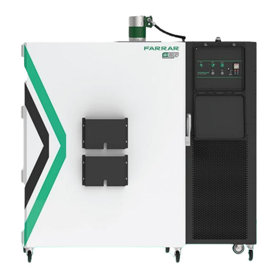
Summary of Contents for Trane FARRAR 4000 Series
- Page 1 4000 SERIES CONTROLLED RATE CHAMBER INSTALLATION, OPERATION, AND MAINTENANCE STANDARD VERSION...
- Page 2 READ THIS INSTRUCTION MANUAL SAFETY PRECAUTIONS User Advisory Failure to read, understand, and follow the instructions in this manual may result in damage to the unit, injury to operating personnel, and poor equipment performance. CAUTION! All internal adjustments and maintenance must be performed by qualified service personnel. Lock Electrocution When plugged in, there is high voltage present on terminals inside the machine space.
-
Page 3: Table Of Contents
4000 SERIES STANDARD CONTROLLED RATE CHAMBER INSTRUCTION MANUAL Introduction Features User Access Heating and Cooling Blower Control System Alarms and Remote Contacts Remote Contacts Terminal Block Connecting to the Remote Contact Terminals Terminal Positions and Descriptions Door Open Alarm – Horn and Strobe Sensor Validation 4000 Series Controlled Rate Chamber Specifications Installation... - Page 4 4000 SERIES CONTROLLED RATE CHAMBER INSTRUCTION MANUAL Control System and Cabinet Use Troubleshooting General Maintenance Periodic Cleaning Cleaning the Condenser (Air-Cooled Units Only) Gasket Maintenance Defrosting the Chamber Evaporator Inspection Water Cooled Condenser Water Regulating Valve Manually Inspect and Flush (Water-Cooled Units Only) Factory Default Watlow®...
-
Page 5: Introduction
4105 Water-cooled - Europe and APAC For more information on these models, refer to the Specifications section of this manual. Features The FARRAR 4000 Series Standard Controlled Rate Chamber consists of three core features: Heating and cooling system Blower Control system The user can adjust various settings to suit specific product requirements. -
Page 6: Heating And Cooling
Heating and Cooling System The 4000 Series Standard Controlled Rate Chamber’s cooling system consists of the following components: Compressors (move heat) Evaporator (absorbs heat) Condenser (rejects heat) Expansion valve (controls flow of refrigerant) The controlled rate chamber creates heat using hot refrigerant gas and resistive heaters embedded in the evaporator assembly. Blower The 4000 Series Standard Controlled Rate Chamber’s blower produces an airflow of 1,000 CFM at a rate of one air change per second. -
Page 7: Alarms And Remote Contacts
Alarms and Remote Contacts Remote Contacts Terminal Block The 4000 Series Standard Controlled Rate Chamber is supplied with remote, non-powered, alarm-signaling dry contacts. Connections are made to a terminal strip in the plastic enclosure on the back of the unit. Connecting to the Remote Contact Terminals There are three sets of dry contacts, as show in Figure 1. -
Page 8: Door Open Alarm - Horn And Strobe
Door Open Alarm – Horn and Strobe In the event of a door opening, while a profile is running, there is a horn and strobe light installed on the top of the unit that will activate. Remote contact terminals 5 & 6 will close. See the chart below for further explanation. 4000 Series Standard Unit State - Door Open Door Position Strobe/Horn State... -
Page 9: 4000 Series Controlled Rate Chamber Specifications
4000 Series Standard Controlled Rate Chamber Specifications Storage Capacity and Dimensions Exterior Dimensions 75 (in.) Width 1,901.5 (mm) 38 (in.) Depth 960.4 (mm) 80 (in.) Height 2,028.8 (mm) Interior Dimensions 34 (in.) Width 863.6 (mm) 27.5 (in.) Depth 698.5 (mm) 43 (in.) Height 1,092.2 (mm) - Page 10 Application, Electrical Requirements, and Refrigeration Systems Application Pharmaceutical Freeze/thaw processing Biopharmaceutical Freeze/thaw processing Electrical Requirements North America 208/240 VAC, 3 Ø, 60Hz, 31 FLA (North America) International 400 VAC, 3 Ø, 50Hz, 24 FLA (International) Circuit Breaker 40 Amp, (North America)/32 Amp (International) Temperature Control Range +40°C to -80°C Ambient Operating Temperature...
- Page 11 Performance Data 4000 Series Model 4000 Temperature Control Range Programmable +40°C to -80°C Internal Air Exchanges 1/second Control IDEC Ramp and soak controller Control Method Proportional hot gas and resistance heat Refrigeration Cascade scroll compressors 5hp and 3.5hp Warranty, North America (U.S. and Canada) 1-year parts and labor Warranty, International 1-year parts only...
- Page 12 Condenser Condenser Type Requirements/Heat Rejection Water Requirements: Pressure Differential ≈ 20 psi (1.38 bar) Water Temperature ≤ (60°F/16°C) Water-Cooler Condenser Water Supply Flow Rate = 6 gpm (22.7 LPM) Water Connections are 1/2" FNPT For 4105 units, A 1/2" MPT x M20 x 1.5 Female Adapter is Provided Flexible High-Pressure Hose Required 1,760 Btu/hr.
-
Page 13: Installation
INSTALLATION Unpacking and Setup This item was thoroughly inspected and carefully packed before shipment, and all necessary precautions were taken to ensure safe arrival. Immediately upon receipt, and before the unit is moved from the receiving area, carefully examine the shipment for loss or damage. -
Page 14: Location And Placement
Location and Placement Once out of the crate, wheel the unit into place near the required power connection. Unit clearance requirements are as follows: To ensure proper airflow, ensure that the unit is (at minimum) the following distances from the nearest wall or ceiling: Unit Clearance Requirements All sides of unit: 6 in. - Page 15 DETAIL 1-Z DETAIL Figure 4: Threaded cabinet drain connector Connect the supplied electrical cord to the evaporator pan receptacle. Connect the other end of the electrical cord to the dedicated power receptacle on the back of the cabinet. See Figure 5 for the exact placement. Figure 5: Electrical cable and cabinet power receptacle 4000 SERIES STANDARD CONTROLLED RATE CHAMBER...
- Page 16 Place the evaporator pan underneath the drain tube. Figure 6: Drain tube connected to evaporator pan For each shelf in the unit, install four shelf clips in the duct sheet. Install two shelf clips in the front and two in the back of the duct sheet at the desired height for the unit.
- Page 17 After installing unit shelves, note the locations of the three chamber access ports within the unit. Two are located on the back of the unit; one is located on the left side of the unit. Note: Sensors may be installed in the chamber access ports to monitor the status of the chamber or samples within the chamber.
-
Page 18: Mechanical
Mechanical 4000 Series Controlled Rate Chamber units with water cooled systems include inlet and outlet water connections for chilled and tower water connections. Inlet and outlet connections are located on the back of the unit and are 0.5 in. female pipe tread (FPT). Note: The 4105 model includes a 22 mm, 1.5 adapter. -
Page 19: Electrical
Electrical The rate chamber is powered by a three-phase circuit, and the refrigeration compressors are required to operate in a specific direction. The unit utilizes a phase monitor to protect the compressors. If the unit does not power on when the POWER switch is activated, switch two of the phase legs in the receptacle or power panel. -
Page 20: Operation
OPERATION Control panel: POWER SWITCH Turns the unit ON and OFF When in the OFF position, the internal control heater power will be OFF, the evaporator fan will be off, the condensate evaporator pan will be off, and compressors will be in pump-down mode only (first-stage refrigeration compressor will turn ON and OFF automatically to remove refrigerant from the evaporator section of the refrigeration system) MODE SWITCH Select the profile to be run when the CYCLE START button is pressed... -
Page 21: Basic Operation And Control Description
Chamber Temperature C Profile Running (Alarm and Error Codes will display) Comms Indicator flashes when connected to a PC using the Watlow® Configurator software Unit Operating Status off: Unit is in standby state or Control Temperature Setpoint Watlow® EZ-ZONE® Configurator Refrigeration Modulation, lit when full refrigeration is requested, otherwise may EZ1 Key to initiate Defrost Cycle... -
Page 22: Interfacing With The 4000 Series Standard Controlled Rate Chamber
INTERFACING WITH THE 4000 SERIES STANDARD CONTROLLED RATE CHAMBER User Selectable Profiles The unit is factory-configured for 3 independent programmable temperature profiles, selectable from the Mode Selection Switch. Pressing the cycle start button while the unit is in standby mode (OFF displayed in the bottom green Watlow® display area) will start the temperature profile that the Mode Selection Switch is set to. -
Page 23: Control Security
Control Security The Watlow® control write security can be set to disable all functions from the Watlow controller front panel. Please refer to the Watlow controller manual for detailed instructions. When write security is set to the highest write security level (level 0), configuring the control system and profiling can only be performed using the USB port supplied on the front of the control panel and the Watlow EZ-ZONE®... -
Page 24: Software Configuration
Software Configuration Using Watlow® EZ-ZONE® Configurator Software To enable a user to configure the PM control using a personal computer (PC), Watlow has provided free software for use. If a copy of this software is not available, insert the CD (Controller Support Tools) into a CD drive and install the software. Alternatively, if viewing this document electronically with an Internet connection, simply click on the link below and download the software from the Watlow website free of charge. - Page 25 After clicking on the "Next" button, the software will scan the network for the zone addresses specified while showing the progress made (as shown in the graphic below. When complete, the software will display all available devices found on the network as shown below.
- Page 26 Once the focus is brought to an individual parameter (single click of the mouse), as is the case for Analog Input 1 in the left column; all that can be set related to that parameter will appear in the center column. The grayed-out fields in the center column indicate that this does not apply to the type of sensor selected.
-
Page 27: Profile Heading
Profile Heading Under Profile, there are 4 Profile sections (Profile 1 Step, Profile 2 Step, Profile 3 Step, and Profile 4 Step). The steps listed under these sub-sections are a continuous list of 40 Steps that can each be individually configured into various step types to accomplish the desired profile temperature parameters. - Page 28 Step Types Time Step: The Time Step is used to change the set point of the cabinet over the specified time. This is the step type that can be used to slowly change the temperature of the cabinet at a controlled rate or can be used to change the temperature of the cabinet as fast as possible by using a short timespan setting.
- Page 29 Wait for Process: The Wait for Process step type guarantees the chamber temperature is at a specific temperature before moving on to the next step in the profile. The “Wait for Process 1” parameter is where this temperature is defined. Step Type Wait For Process Notes...
- Page 30 End: The End step will turn off all functions in the unit and return the unit to the standby state. The temperature in the unit will no longer be controlled while in the standby state. Step Type Notes Target Set Point Loop 1 -18ºC Target Set Point Loop 2 -18ºC...
-
Page 31: Profile Examples
Profile Examples Default Profile 1 Example Click on Profile 1 step then Profile 1 Step 1. This step is the first to use when configuring Profile 1. Note, the only options available for the Step Type (Time) are Target Set Point 1, Hours, Minutes, Seconds, Event 1, and Event 2. All others are grayed out. - Page 32 Default Profile 1, Step 3 Example Screen Default Profile 1, Step 3 Example Screen: Profile 1 Step 3 is a Wait for Event step, the Wait for Event monitors the Wait for Event 1 and 2. If either is On, the profile waits at that step until the stop button is pressed. Event 1 is On which continues to activate the refrigeration liquid, hot gas solenoid valves, and profile running indicator on the mode switch.
-
Page 33: Sample Profile
Sample Profile Note this is a sample profile only and is not loaded into the controller. The step type settings from above should be followed to guarantee proper profile configuration. A profile controls the heating, cooling, and internal circulation fan. This unit contains 40 profile steps broken down into 4 profiles of 10 steps each. -
Page 34: Modifying Or Creating A Profile Via The Watlow® Control Panel Pushbuttons
Modifying or Creating a Profile via the Watlow® Control Panel Pushbuttons Note that modifying or creating a profile will overwrite the existing profile. Mode Switch Profile 1 must start on (Watlow Profile 1 Step 1), Mode Switch Profile 2 must start on step (Watlow Profile 2 step 11) and Mode Switch Profile 3 must start on (Watlow Profile 3 Step 21) to operate properly. -
Page 35: Control System And Cabinet Use
CONTROL SYSTEM AND CABINET USE After the unit is turned on and a profile is selected, the unit is ready to run the profile. Load the unit with the product you wish to condition then close and latch the door. Press the START button. This energizes the liquid and hot gas solenoids along with the evaporator fan via the Watlow®... -
Page 36: Troubleshooting
TROUBLESHOOTING The unit is connected to the power source, and the power switch is ON, but there is no light on the power switch or Watlow® control. Verify input voltage on all 3 phase legs. On initial startup check all 3 phases. The Controlled Rate Chamber monitors for the correct phase sequence. Switch 2 of the phase wires at the receptacle or power panel. -
Page 37: General Maintenance
GENERAL MAINTENANCE The 4000 Series Standard Controlled Rate Chamber Series unit must be turned OFF and UNPLUGGED during all mainte- nance or service. Wear proper PPE at all times. Warning! Electrical Hazard Hazards! Periodic Cleaning Beginning with the initial installation, the interior surfaces of the cabinet should be periodically wiped down with a solution of warm water and laboratory detergent. -
Page 38: Gasket Maintenance
Gasket Maintenance Periodically check the gaskets around the door for punctures or tears. Leaks are indicated by a streak of frost which forms at the point of gasket failure. Make sure that the cabinet is level. Keep the door gaskets clean and frost-free by wiping gently with a soft cloth. -
Page 39: Water Cooled Condenser Water Regulating Valve Manually Inspect And Flush
Water-Cooled Condenser Water Regulating Valve Manually Inspect and Flush (water-cooled only 4102/4105) The water-cooled condenser water regulating valve should be inspected every six (6) months. This is a visual and operational inspection. Complete the following steps: Turn off the power to the freezer. Remove side panel cover (20 screws). -
Page 40: Warranty
International Every FARRAR 4000 Series Standard Controlled Rate Chamber is backed by a 1-year parts warranty. An extended 3-year parts warranty is also available for purchase. Please contact FARRAR or your local FARRAR distributor for more information. -
Page 41: Contacting Farrar
CONTACTING FARRAR When contacting FARRAR® or local FARRAR distributors, please have the following information readily available if service is required: Model Number: Serial Number: Date of Purchase: Purchase Order: FOR CUSTOMER ASSISTANCE: The FARRAR products support team is ready to answer any questions. In addition to technical support, FARRAR offers various accessories, extended warranty programs, and validation services. -
Page 42: Appendix A: Hazard Symbols
APPENDIX A: HAZARD SYMBOLS This symbol alerts the user to important operating and/or maintenance instructions. It may be used alone or with other safety symbols. Read the accompanying text carefully. Important Alert Potential electrical hazards. Only qualified service personnel should perform the instructions and procedures associated with this symbol. - Page 43 All trademarks referenced are the trademarks of their respective owners. ©2024 TRANE TECHNOLOGIES LIFE SCIENCES LLC. All Rights Reserved. LSFU-PRG015A-EN | 3-30-24 Note: Trane Technologies has a policy of continuous product and product data improvement and reserves the right to change design and specifications without notice.
Need help?
Do you have a question about the FARRAR 4000 Series and is the answer not in the manual?
Questions and answers