Table of Contents
Advertisement
Quick Links
1 button IP professional metal video intercom doorbell - POE
EDS101S & EDS101B
Legal Information
About this Manual
The Manual includes instructions for using and managing the Product. Pictures, charts, images and
all other information hereinafter are for description and explanation only. The information
contained in the Manual is subject to change, without notice, due to firmware updates or other
reasons. Please find the latest version of this Manual at the company website Please use this
Manual with the guidance and assistance of professionals trained in supporting the Product.
Trademarks Acknowledgement
Trademarks and logos mentioned are the properties of their respective owners.
LEGAL DISCLAIMER
TO THE MAXIMUM EXTENT PERMITTED BY APPLICABLE LAW, THIS MANUAL AND THE PRODUCT
i
Advertisement
Table of Contents

Related Manuals for EtiamPro EDS101S


Summary of Contents for EtiamPro EDS101S
- Page 1 1 button IP professional metal video intercom doorbell - POE EDS101S & EDS101B Legal Information About this Manual The Manual includes instructions for using and managing the Product. Pictures, charts, images and all other information hereinafter are for description and explanation only. The information contained in the Manual is subject to change, without notice, due to firmware updates or other reasons.
- Page 2 1 button IP professional metal video intercom doorbell - POE DESCRIBED, WITH ITS HARDWARE, SOFTWARE AND FIRMWARE, ARE PROVIDED “AS IS” AND “WITH ALL FAULTS AND ERRORS”. OUR COMPANY MAKES NO WARRANTIES, EXPRESS OR IMPLIED, INCLUDING WITHOUT LIMITATION, MERCHANTABILITY, SATISFACTORY QUALITY, OR FITNESS FOR A PARTICULAR PURPOSE.
- Page 3 1 button IP professional metal video intercom doorbell - POE Symbol Conventions The symbols that may be found in this document are defined as follows. Symbol Description Indicates a hazardous situation which, if not avoided, will or could Danger result in death or serious injury. Indicates a potentially hazardous situation which, if not avoided, Caution could result in equipment damage, data loss, performance...
- Page 4 1 button IP professional metal video intercom doorbell - POE Safety Instruction Warning ● All the electronic operation should be strictly compliance with the electrical safety regulations, fire prevention regulations and other related regulations in your local region. ● Please use the power adapter, which is provided by normal company. The power consumption cannot be less than the required value.
- Page 5 1 button IP professional metal video intercom doorbell - POE ● Improper use or replacement of the battery may result in hazard of explosion. Replace with the same or equivalent type only. Dispose of used batteries according to the instructions provided by the battery manufacturer.
- Page 6 EMC Directive 2014/30/EU, the RoHS Directive 2011/65/EU RED Declaration of Conformity Hereby, Velleman Group nv declares that the radio equipment type EDS101S & EDS101B is in compliance with Directive 2014/53/EU. The full text of the EU declaration of conformity is available at the following internet address: www.velleman.eu...
- Page 7 1 button IP professional metal video intercom doorbell - POE 802.11g:15 dBm +/- 1.5 dBm 802.11n(ht20):14 dBm +/- 1.5 dBm 802.11n(ht40):12 dBm +/- 1.5 dBm Operating frequency range 2.4-2.4835 GHz Network standards IEEE 802.11 b, g, n (2.4 GHz single band) 2012/19/EU (WEEE directive): Products marked with this symbol cannot be disposed of as unsorted municipal waste in the European Union.
- Page 8 1 button IP professional metal video intercom doorbell - POE l'intention des autres utilisateurs, il faut choisir le type d'antenne et son gain de sorte que la puissance isotrope rayonnée équivalente (p.i.r.e.) ne dépasse pas l'intensité nécessaire à l'établissement d'une communication satisfaisante. This equipment should be installed and operated with a minimum distance 20cm between the radiator and your body.
-
Page 9: Table Of Contents
1 button IP professional metal video intercom doorbell - POE Contents Chapter 2 Appearance ........................ 1 Chapter 3 Terminal and Wiring Description ................3 3.1 Terminal Description ......................3 3.2 Wiring Description ......................... 4 3.2.1 Door call linkage wiring ....................4 3.2.2 Door Lock Wiring .................... - Page 10 1 button IP professional metal video intercom doorbell - POE 6.4.8 Intercom Settings ..................... 39 6.4.9 Access Control Settings .................... 42 Chapter 7 Configuration via Client Software ................46 7.1 Device Management ......................46 7.1.1 Add Online Device ....................46 7.1.2 Add Device by IP Address..................
-
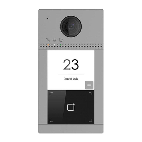
Page 11: Chapter 2 Appearance
Video Intercom Villa Door Station User Manual Chapter 2 Appearance Single-Button Villa Door Station Figure 2-1 Single-Button Villa Door Station Appearance... - Page 12 Video Intercom Villa Door Station User Manual Table 2-1 Description Description Microphone Indicator Unlock (Green)/ Call (Orange)/ Communicate (White) Camera Loudspeaker Button Card Reading Area IR Light TF Card Slot (Reserved) & Debugging Port Terminals...
-
Page 13: Chapter 3 Terminal And Wiring Description
Video Intercom Villa Door Station User Manual Chapter 3 Terminal and Wiring Description 3.1 Terminal Description Terminal Description Table 3-1 Description of Terminal and Interfaces Name Interface Description Relay Output 2 (NC) COM2 Common Interface Relay Output 2 (NO) Grounding DOOR Relay Output 1 (NO) COM1... -
Page 14: Wiring Description
Video Intercom Villa Door Station User Manual Name Interface Description Note Before accessing to the Exit Button, select Input as Exit Button in I/O Settings page first. 485+ RS-485 RS-485 Communication Interface 485- 12 VDC Power Input 12 VDC Input Network Network Interface 3.2 Wiring Description... - Page 15 Video Intercom Villa Door Station User Manual NO2/COM2/NC2 to be electric lock with Guarding Vision client software. 3.2.2 Door call connection to a classic doorbell or home automation system. The relay output 2 will be closed for 1 second when the door button is pressed. You can connect the relays to a classic doorbell or an input of a home automation system.
- Page 16 Video Intercom Villa Door Station User Manual Software configuration: This is preconfigured, but can be changed via the configuration menu, intercom, I/O settings:...
-
Page 17: Door Contact Wiring
Video Intercom Villa Door Station User Manual 3.2.3 Door Contact Wiring Figure 3-4 Door Contact Wiring Note If the door contact is not used, the corresponding input interface needs to be grounded. Otherwise the door light will stay open. -
Page 18: Exit Button Wiring
Video Intercom Villa Door Station User Manual 3.2.4 Exit Button Wiring Figure 3-5 Exit Button Wiring... -
Page 19: Alarm Input Device Wiring
Video Intercom Villa Door Station User Manual 3.2.5 Alarm Input Device Wiring Figure 3-6 Alarm Input Device Wiring... -
Page 20: Chapter 4 Installation
Video Intercom Villa Door Station User Manual Chapter 4 Installation Note ● Make sure the device in the package is in good condition and all the assembly parts are included. ● Make sure your power supply matches your door station. ●... -
Page 21: Surface Mounting With Protective Shield
Video Intercom Villa Door Station User Manual 4.2 Surface Mounting with Protective Shield Before You Start ● Tools that you need to prepare for installation: Drill (ø2.846) and gradienter. ● Purchase the protective shield before installation. Steps 1. Stick the mounting template on the wall. Drill screw holes according to the mounting template. Remove the template from the wall. - Page 22 Video Intercom Villa Door Station User Manual Figure 4-2 Mounting Template 2. Align the protective shield with mounting template. 3. Secure the mounting plate on the wall with 4 supplied screws according to the screw holes. 4. Secure the device on the mounting plate with 4 supplied set screws. 5.
-
Page 23: Surface Mounting Without Protective Shield
Video Intercom Villa Door Station User Manual Figure 4-3 Surface Mounting with Protective Shield 4.3 Surface Mounting without Protective Shield Before You Start Tools that you need to prepare for installation: Drill (ø2.846) and gradienter. Steps 1. Stick the mounting template on the wall. Drill screw holes according to the mounting template. Remove the template from the wall. - Page 24 Video Intercom Villa Door Station User Manual Figure 4-4 Mounting Template 2. Secure the mounting plate on the wall with 4 supplied screws according to the screw holes. 3. Secure the device on the mounting plate with 4 supplied set screws. 4.
- Page 25 Video Intercom Villa Door Station User Manual Figure 4-5 Surface Mounting without Protective Shield...
-
Page 26: Chapter 5 Activation
Video Intercom Villa Door Station User Manual Chapter 5 Activation ONLY NECESSARY AFTER A FULL RESET! 5.1 Activate Device via Web You are required to activate the device first by setting a strong password for it before you can use the device. -
Page 27: Edit Network Parameters
Video Intercom Villa Door Station User Manual 4. Create a password, and confirm the password. Note We highly recommend you to create a strong password of your own choosing (using a minimum of 8 characters, including at least three kinds of following categories: upper case letters, lower case letters, numbers, and special characters) in order to increase the security of your product. -
Page 28: Chapter 6 Remote Configuration Via Web
Video Intercom Villa Door Station User Manual Chapter 6 Remote Configuration via Web 6.1 Live View In the browser address bar, enter the IP address of the device, and press the Enter key to enter the login page. Enter the user name and password and click Login to enter the Live View page. Or you can click Live View to enter the page. -
Page 29: Device Management
Video Intercom Villa Door Station User Manual Figure 6-2 User Management ● Click Add to add users. Enter the Employee ID, Name, Floor No. and Room No., Set the Start Time and End Time. You can set the user as Administrator. ●... -
Page 30: Parameters Settings
Video Intercom Villa Door Station User Manual Export Click Export to export the information to the PC. Delete Select the device and click Delete to remove the selected device from the list. Synchronize Click Synchronize and enable Synchronize for device synchronization. Note When enabling the function, the activated devices will synchronize parameters. - Page 31 Video Intercom Villa Door Station User Manual running the web browser. Figure 6-4 Local Parameters Live View Parameters Stream Type Set the stream type as Main Stream or Sub-stream. Play Performance Set the live view performance to Shortest Delay, Balanced or Fluent. Auto Start Live View Check Yes to enable the function.
-
Page 32: System Settings
Video Intercom Villa Door Station User Manual Click Save to enable the settings. Picture and Clip Settings Save snapshots in live view to Set the saving path of the manually captured pictures in live view mode. Note You can click Browse to change the directory for saving the clips and pictures, and click Open to open the set folder of clips and picture saving. - Page 33 Video Intercom Villa Door Station User Manual Figure 6-5 Maintenance ● Reboot: Click Reboot to reboot the device. Default Click Default to reset all the parameters, except the IP parameters and user information, to the default settings. Restore All Click Restore All to restore all parameters to default settings. ●...
-
Page 34: Network Settings
Video Intercom Villa Door Station User Manual Administrator can edit the permission for the users. Note We highly recommend you to create a strong password of your own choosing (using a minimum of 8 characters, including at least three kinds of following categories: upper case letters, lower case letters, numbers, and special characters) in order to increase the security of your product. - Page 35 Video Intercom Villa Door Station User Manual Figure 6-6 TCP/IP Settings 2. Configure the network parameters. – Check DHCP, the device will get the parameters automatically. – Set the IPv4 Address, IPv4 Subnet Mask and IPv4 Default Gateway manually. 3. Configure the corresponding DNS server parameters. 4.
- Page 36 Video Intercom Villa Door Station User Manual Figure 6-7 Port Settings 2. Set the ports of the device. HTTP Port The default port number is 80, and it can be changed to any port No. which is not occupied. HTTPS Port The default port number is 443, and it can be changed to any port No.
- Page 37 Video Intercom Villa Door Station User Manual Figure 6-8 Wi-Fi Settings 2. Select a Wi-Fi and click to pop-up the dialog box. 3. Enter the password of the wireless network to connect. 4. Optional: Click Network Settings to set the parameters of WLAN. SIP Setting Steps 1.
- Page 38 Video Intercom Villa Door Station User Manual 4. Click Save to enable the settings. FTP Settings Steps 1. Click Network → Advanced → FTP to enter the settings page. Figure 6-10 FTP Settings 2. Check Enable FTP. 3. Select Server Type.
-
Page 39: Video & Audio Settings
Video Intercom Villa Door Station User Manual 4. Input the Server IP Address and Port. 5. Configure the FTP Settings, and the user name and password are required for the server login. 6. Set the Directory Structure, Parent Directory and Child Directory. 7. - Page 40 Video Intercom Villa Door Station User Manual Figure 6-11 Video Parameters 2. Select the Stream Type. 3. Configure the video parameters. Stream Type Select the stream type to main stream or sub stream. Video Type Select the stream type to video stream, or video & audio composite stream. The audio signal will be recorded only when the Video Type is Video &...
- Page 41 Video Intercom Villa Door Station User Manual Max. Bitrate Set the max. bitrate from 32 to 16384 Kbps. The higher value corresponds to the higher video quality, but the better bandwidth is required. Video Encoding The device supports H.264. I Frame Interval Set I Frame Interval from 1 to 400.
-
Page 42: Image Settings
Video Intercom Villa Door Station User Manual 6.4.5 Image Settings Display Settings Configure the image adjustment, backlight settings and other parameters in display settings. Steps 1. Click Image → Display Settings to enter the display settings page. Figure 6-13 Display Settings 2. - Page 43 Video Intercom Villa Door Station User Manual Figure 6-14 Day/Night Mode Set Day Mode or Night Mode manually.Set the mode as Auto and edit the sensitivity according to your needs.Set the mode as Scheduled-Switch. Set the start time and end time. Note Daytime is from configured start time to configured time.
-
Page 44: Event Settings
Video Intercom Villa Door Station User Manual 6. Click Save to enable the settings. OSD Settings You can customize the camera name, time/date format, display mode, and OSD size displayed on the live view. Steps 1. Click Image → OSD Settings to enter the settings page. 2. - Page 45 Video Intercom Villa Door Station User Manual Figure 6-16 Motion Detection 2. Slide Enable Motion Detection to enable the function. 3. Click Draw Area. Click and drag the mouse on the live video to draw a motion detection area. Click Save to save the settings. Clear Area Click X to clear all of the areas.
- Page 46 Video Intercom Villa Door Station User Manual 5. Click on the time bar and drag the mouse to select the time period. Click Save to save the settings. Delete Schedule Click Delete to delete the current arming schedule. 6. Click Linkage Method to enable the linkages. Notify Security Center Send an exception or alarm signal to the remote management software when an event occurs.
-
Page 47: Schedule Settings
Video Intercom Villa Door Station User Manual Figure 6-17 Event Linkage 2. Select the Major Type as Device Event or Door Event. 3. Select the type of the Normal Linkage for the event. 4. Click Save to enable the settings. 6.4.7 Schedule Settings You can create call schedule, or else the device will call indoor station all day by default. - Page 48 Video Intercom Villa Door Station User Manual 2. Click the next row below Enable Indoor Station All Day by Default. 3. Enter Schedule Name. 4. Select Call Type. 5. Set Weekly Schedule. 1) Click Weekly Schedule. Figure 6-18 Weekly Schedule 2) Drag mouse to set the schedule according to the actual needs.
-
Page 49: Intercom Settings
Video Intercom Villa Door Station User Manual Figure 6-19 Holiday Schedule 2) Click Add. 3) Set Start Time and End Time. 4) Select Call Type. 5) Drag mouse to set the schedule according to the actual needs. 6) Click OK. 7) You can edit or delete the schedule according to the actual needs. - Page 50 Video Intercom Villa Door Station User Manual Figure 6-20 Device No. Settings 2. Select the device type from the drop-down list, and set the corresponding information. 3. Click Save to enable the device number configuration. Note ● For main door station (D series or V series), the serial No. is 0. ●...
- Page 51 Video Intercom Villa Door Station User Manual Configure Max. Call Duration, Max. Message Duration, Max. Ring Duration, and click Save. Note ● Max. call duration between the module indoor station and client ranges from 90 s to 120 s. The call will end automatically when the actual calling duration is longer than the configured one.
-
Page 52: Access Control Settings
Video Intercom Villa Door Station User Manual 2. Select I/O input No., input mode, output No., and output mode. 3. Click Save to enable the settings. Note ● For door station, there are 4 I/O input terminals. By default, Terminal 1 and 2 correspond to Door Status. - Page 53 Video Intercom Villa Door Station User Manual Figure 6-23 Door Parameters 2. Select Door No., and edit the Name. 3. Set Open Duration. When the time to open over the open duration you set, the door will be locked again. 4.
- Page 54 Video Intercom Villa Door Station User Manual Figure 6-24 Elevator Control 2. Check to enable elevator control function. 3. Select an Elevator No., and select an elevator controller type for the elevator. 4. Set the Negative Floor. 5. Select the Interface Type as RS-485 or Network Interface. And enable the elevator control. –...
- Page 55 Video Intercom Villa Door Station User Manual ● Up to 10 negative floors can be added. ● Make sure the interface types of elevator controllers, which are connected to the same door station are consistent.
-
Page 56: Chapter 7 Configuration Via Client Software
Video Intercom Villa Door Station User Manual Chapter 7 Configuration via Client Software 7.1 Device Management Device management includes device activation, adding device, editing device, and deleting device, and so on. After running the Guarding Vision, video intercom devices should be added to the client software for remote configuration and management. -
Page 57: Add Device By Ip Segment
Video Intercom Villa Door Station User Manual 7.1.3 Add Device by IP Segment You can add many devices at once whose IP addresses are among the IP segment. Steps 1. Click +Add to pop up the dialog box. 2. Select IP Segment as Adding Mode. 3. -
Page 58: Person Management
Video Intercom Villa Door Station User Manual Note ● The lower-level organizations will be deleted as well if you delete an organization. ● Make sure there is no person added under the organization, or the organization cannot be deleted. 7.4 Person Management After adding the organization, you can add person to the organization and manage the added person such as issuing cards in batch, importing and exporting person's information in batch, etc. -
Page 59: Modify And Delete Person
Video Intercom Villa Door Station User Manual Click Remote Take the person's photo with the collection device. Collection 3. Issue the card for the person. 1) Click Credential → Card. 2) Click + to pop up the Add Card dialog. 3) Select Normal Card as Card Type. -
Page 60: Import And Export Person Information
Video Intercom Villa Door Station User Manual 7.4.4 Import and Export Person Information The person information can be imported and exported in batch. Steps 1. Exporting Person: You can export the added persons' information in Excel format to the local 1) After adding the person, you can click Export Person to pop up the following dialog. -
Page 61: Issue Card In Batch
Video Intercom Villa Door Station User Manual 7.4.6 Issue Card in Batch You can issue multiple cards for the person with no card issued in batch. Steps 1. Click Batch Issue Cards to enter the dialog page. All the added person with no card issued will display in the Person(s) with No Card Issued list. -
Page 62: Permission Settings
Video Intercom Villa Door Station User Manual Figure 7-2 Card Settings 3. Select Card Type and Card No. Type. 4. Click OK to save the settings. Result After issuing the card to the person, the person and card information will display in the Person(s) with Card Issued list. -
Page 63: Video Intercom Settings
Video Intercom Villa Door Station User Manual 2. Click +Add to pop up the adding dialog box. 3. Configure the parameters. 1) Enter the Name of the permission. 2) Select the Template of the schedule. 3) Check the person to Selected according to your needs. 4) Check the device to Selected according to your needs. -
Page 64: Release Notice
Video Intercom Villa Door Station User Manual Adjust the Volume of Click to adjust the volume of microphone. Microphone Unlock Remotely For door station, you can click to open the door remotely. Note ● One video intercom device can only connect with one client software. ●... -
Page 65: Search Video Intercom Information
Video Intercom Villa Door Station User Manual 7.5.3 Search Video Intercom Information Search Call Logs Steps 1. On the Video Intercom page, click Call Log to enter the page. Figure 7-3 Search Call Logs 2. Set the search conditions, including call status, device type, start time and end time. Call Status Click ˅... -
Page 66: Upload Armed Information
Video Intercom Villa Door Station User Manual 4. Optional: Check the detailed information of searched call logs, such as call status, ring/speaking duration, device name, resident organization, etc. 5. Optional: Input keywords in the Search field to filter the desired log. 6. - Page 67 UD29245N...
- Page 68 - defecten veroorzaakt door opzet, nalatigheid of door een onoordeelkundige behandeling, slecht onderhoud of abnormaal gebruik of gebruik van het toestel strijdig met de voorschriften van de fabrikant. Velleman® Service and Quality Warranty - schade ten gevolge van een commercieel, professioneel of collectief gebruik Since its foundation in 1972, Velleman®...
- Page 69 Feuchtigkeit, ...), sowie auch der Inhalt (z.B. Datenverlust), Entschädigung für eventuellen Gewinnausfall. Garantía de servicio y calidad Velleman® - Verbrauchsgüter, Teile oder Zubehörteile, die durch normalen Gebrauch dem Desde su fundación en 1972 Velleman® ha adquirido una amplia experiencia Verschleiß ausgesetzt sind, wie z.B. Batterien (nicht nur aufladbare, sondern como distribuidor en el sector de la electrónica en más de 85 países.
- Page 70 • qualquer garantia comercial não prevalece as condições aqui mencionadas. A lista pode ser sujeita a um complemento conforme o tipo de artigo e estar mencionada no manual de utilização. Made in PRC Imported for EtiamPro by Velleman Group nv Legen Heirweg 33, 9890 Gavere, Belgium www.velleman.eu...
Need help?
Do you have a question about the EDS101S and is the answer not in the manual?
Questions and answers