Advertisement
SERVICE MANUAL
EN
2812
0891
IMPORTANT: Read and follow all instructions and SAFETY PRECAUTIONS
before using this equipment. Retain for future reference.
77-3141-R7 (4/2024)
AIR MOTOR DRIVES AND AGITATORS
FOR PRESSURE FEED TANKS
31-452-CE
QMS-430-CE
1 / 16
QMS-431-CE
QMS-433-CE
QMS-434-CE
www.carlisleft.com
Advertisement
Table of Contents

Related Manuals for Carlisle BINKS QMS-430-CE


Summary of Contents for Carlisle BINKS QMS-430-CE
- Page 1 SERVICE MANUAL 2812 0891 AIR MOTOR DRIVES AND AGITATORS FOR PRESSURE FEED TANKS IMPORTANT: Read and follow all instructions and SAFETY PRECAUTIONS before using this equipment. Retain for future reference. QMS-431-CE QMS-433-CE QMS-434-CE 31-452-CE QMS-430-CE 77-3141-R7 (4/2024) 1 / 16 www.carlisleft.com...
- Page 2 AIR MOTOR DRIVES AND AGITATORS FOR PRESSURE FEED TANKS IMPORTANT: Read and follow all instructions and SAFETY PRECAUTIONS before using this equipment. Retain for future reference. DESCRIPTION This manual covers the following models: 31-452-CE Air motor drive with 15:1 gear reduction. Includes air adjusting valve for speed control with hose and fittings for tank regulator connection.
- Page 3 In this part sheet, the words WARNING, CAUTION and NOTE are used to emphasize important safety information as follows: WARNING NOTE CAUTION Hazards or unsafe practices which Hazards or unsafe practices which could result in severe personal Important installation, operation or could result in minor personal injury, injury, death or substantial property maintenance information.
-
Page 4: Installation
SPECIFICATION – AGITATOR CROSS REFERENCE CHART Agitator Code Type of Agitation Used with: Max rpm recommended pressure 31-452-CE Indirect Geared Drive Agitator & motor QMS-431-CE, 433-CE & 434-CE 6.2 bar QMS-431-CE Agitator only (less drive) for 8 ltr tanks 83S-213-CE 6.2 bar QMS-433-CE Agitator only (less drive) for 40 ltr tanks... -
Page 5: Preventative Maintenance
QMS-431-CE, 433-CE AND 434-CE CAUTION AGITATOR—INSTALLATION INTO PRESSURE FEED TANK (FIG. 7) OPERATION 1. Follow the pressure relief Failure to operate and maintain these agitators correctly Fig 2 could result in premature motor failure and void warranty. procedure at the start of the INSTALLATION section. -
Page 6: Replacement Of Parts
ALL AIR MOTORS 5. The shaft can now be withdrawn from the bearing housing (25). Be careful with the shaft seal (27) as any burrs or 1. Lubricate Air Motor as per Installation section on page 3. dried paint could damage the lip seal. 2. - Page 7 31-437-K AIR MOTOR REPLACEMENT OF 12. Place the end plate gasket (41) on the body of dead end (40). If the original is damaged, replace with a new one PARTS (FOR 31-452-CE) supplied in the service kit. 1. Remove the end cap (36). 13.
- Page 8 FIG. 5 31-452-CE GEAR REDUCTION DRIVE 40 & 60 LITRE CONFIGURATION 8 LITRE CONFIGURATION 31-452-CE 15:1 GEAR REDUCTION DRIVE ASSEMBLY ITEM ITEM PART NO. DESCRIPTION PART NO. DESCRIPTION QTY. QTY. QMS-35 AIR MOTOR SUPPORT HA-57011 AIR HOSE HEX HEAD CAP SCREW, Purchase Locally STREET TEE, 1/4"...
- Page 9 INSTALLATION—DRIVE UNIT 31-452-CE Rotate the drive unit to the desired position. Then tighten the WARNING cap screws (2) Use 9/16 wrench. Before attempting any installation of agitators onto pressure feed tanks, the tanks must be relieved of pressure as high pressure can cause a serious injury. Pressure is maintained in a pressure tank after the system has been shut down.
-
Page 10: Service Checks
FIG. 7 QMS-431-CE, 433-CE AND 434-CE AGITATOR PARTS LIST Ind. Replacement Ref. No. Description Parts Part No. Req'd. QMS-431-CE Agitator Assembly 8L (includes items 20 to 31) QMS-433-CE Agitator Assembly 40L QMS-434-CE Agitator Assembly 60L QMS-46 Retaining Nut QMS-447 Thrust Collar Kit (includes items 22 and 23) —... - Page 11 FIG. 8 PT-427-CE, PT-418-CE, PT-419-CE & PT-428-CE PARTS LIST Ind. Ref. Replacement Description Parts Part No. Req'd. PT-410 * 35 Air Motor Assembly QMS-455 QS-190 End Cap PT-65 * 37 ——– End Cap Gasket PT-58 Bearing ——– Screw (1/4”-28 x 1/2”) * 40 ——–...
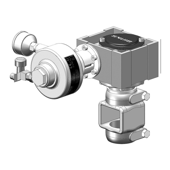
- Page 12 FIG. 9 QMS-430-CE PARTS LIST Ind. Ref. Replacement Description Parts Part No. Req'd. ——-- Street Elbow 1/4”(M) 1/4”NPT(F) H-2008 Nipple 1/4” NPS(M) HAV-500 Air Adjusting Valve HA-57001 Hose assembly ——- Service Tee 1/4” KK-4991 Agitator Kit Motor Assembly QMS-428 (incl parts #4 to 18). Use #1, 2 &...
- Page 13 15:1 AGITATOR DRIVE FLEX COUPLING INSTALLATION Assemble one coupling jaw from the coupling assembly (4f) onto the air motor shaft (4a). Make sure to keep the coupling face flush with the end of the motor shaft as shown. Apply Loctite 243 (or equivalent) to set screw threads. Align the set screw to motor shaft flat and tighten.
- Page 14 NOTES www.carlisleft.com 14 / 16 77-3141-R7 (4/2024)
- Page 15 IN ACCORDANCE WITH PED 2014/68/EC Carlisle Fluid Technology confirms that the products listed below, defined under the Pressure Equipment Directive (PED) 2014/68/EC as ‘Pressure Accessories’ , are below or equal to the limits set out in points (a), (b) and (c) of paragraph 1 and in paragraph 2 respectively and have been designed and manufactured in accordance with Sound Engineering Practice (SEP) Article 4, Paragraph 3.
-
Page 16: Warranty Policy
This product is covered by Carlisle Fluid Technologies’ materials and workmanship limited warranty. The use of any parts or accessories, from a source other than Carlisle Fluid Technologies, will void all warranties. Failure to reasonably follow any maintenance guidance provided may invalidate any warranty.
Need help?
Do you have a question about the BINKS QMS-430-CE and is the answer not in the manual?
Questions and answers