Table of Contents
Advertisement
Quick Links
Advertisement
Table of Contents

Related Manuals for Toro 74938


Summary of Contents for Toro 74938
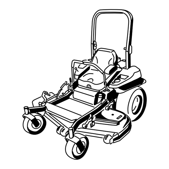
- Page 1 Z Master ® Professional 6000 Series Riding Mower with 60in or 72in TURBO FORCE ® Side Discharge Mower Model No. 74936—Serial No. 313000001 and Up Model No. 74938—Serial No. 313000001 and Up g019887 *3375-649* A Register at www.Toro.com. Original Instructions (EN)
-
Page 2: Figure 1
State of product properly and safely. California to cause cancer, birth defects, You may contact Toro directly at www.Toro.com for product or other reproductive harm. and accessory information, help finding a dealer, or to register your product. -
Page 3: Table Of Contents
This manual identifies potential hazards and has safety Lubrication ...............31 messages identified by the safety alert symbol (Figure 2), Greasing and Lubrication ........31 which signals a hazard that may cause serious injury or death Where to Grease the Mower........31 if you do not follow the recommended precautions. Lubricate Caster Wheel Hubs........32 Engine Maintenance ..........33 Servicing the Air Cleaner .........33... -
Page 4: Safety
Operation Safety • Lightning can cause severe injury or death. If lightning is seen or thunder is heard in the area, do not operate Improper use or maintenance by the operator or owner can the machine; seek shelter. result in injury. To reduce the potential for injury, comply with these safety instructions and always pay attention to the safety •... - Page 5 Hauling • Extinguish all cigarettes, cigars, pipes, and other sources of ignition. • Use care when loading or unloading the machine into • Use only an approved fuel container. or from a trailer or truck. • Never remove fuel cap or add fuel with the engine •...
-
Page 6: Slope Indicator
Slope Indicator G011841 Figure 3 This page may be copied for personal use. 1. The maximum slope you can safely operate the machine on is 15 degrees. Use the slope chart to determine the degree of slope of hills before operating. Do not operate this machine on a slope greater than 15 degrees. Fold along the appropriate line to match the recommended slope. -
Page 7: Safety And Instructional Decals
Safety and Instructional Decals Safety decals and instructions are easily visible to the operator and are located near any area of potential danger. Replace any decal that is damaged or lost. 68-8340 1-403005 98-5954 103-2076 54-9220 58-6520 1. Grease 105-7798 66-1340... - Page 8 109-7232 110-2067 107-2102 107-3969 1. Warning—read the Operator's Manual. 2. Crushing hazard, mower—engage the parking brake, stop 110-2068 the engine, and remove the ignition key before working under the mower. 1. Read the Operator's Manual. 114-4466 1. Main, 25A 3. Charge, 25A 4.
- Page 9 116-0205 115-7445 1. Grease pulleys and spindles 2. Maintenance interval—50 hours 116-0211 116-0090 116-0752 116-0157 1. Locked 2. Unlocked...
- Page 10 116-1654 116-4858 116-1716 1. Fuel 6. Hour meter 116-5944 2. Empty 7. PTO 3. Half 8. Parking brake 4. Full 9. Neutral 5. Battery 10. Operator presence switch 116-2643 Battery Symbols Some or all of these symbols are on your battery 1.
- Page 11 Manufacturer's Mark 1. Indicates the blade is identified as a part from the original machine manufacturer. 120-5897 1. Choke 4. Slow 2. Fast 5. Power take-off (PTO), Blade control switch 3. Continuous variable setting 109-7069...
-
Page 12: Product Overview
Hour Meter Product Overview The hour meter records the number of hours the engine has operated. It operates when the engine is running. Use these times for scheduling regular maintenance (Figure 6). Fuel Gauge The fuel gauge is located with the hour meter and the bars light up when the ignition switch is on (Figure 6). -
Page 13: Specifications
74938 1349 lb (612 kg) its capabilities. Contact your Authorized Service Dealer or Distributor or go to www.Toro.com for a list of all approved 74960CP 1269 lb (576 kg) attachments and accessories. -
Page 14: Operation
Operation DANGER In certain conditions during fueling, static Note: Determine the left and right sides of the machine electricity can be released causing a spark which from the normal operating position. can ignite the gasoline vapors. A fire or explosion from gasoline can burn you and others and can Adding Fuel damage property. -
Page 15: Checking The Engine Oil Level
Filling the Fuel Tank Breaking In a New Machine Note: Do not fill the fuel tank completely full. Fill the fuel New engines take time to develop full power. Mower decks tank to the bottom of the filler neck. The empty space in the and drive systems have higher friction when new, placing tank allows the gasoline to expand. -
Page 16: Think Safety First
DANGER Operating on wet grass or steep slopes can cause sliding and loss of control. Wheels dropping over edges can cause rollovers, which may result in serious injury, death or drowning. There is no rollover protection when the roll bar is down. -
Page 17: Operating The Parking Brake
Operating the Mower Blade The use of protective equipment for eyes, ears, feet and head is recommended. Control Switch (PTO) The blade control switch (PTO) starts and stops the mower blades and any powered attachments. Engaging the Blade Control Switch G009027 (PTO) Figure 10... -
Page 18: Operating The Throttle
Operating the Throttle Important: Do not engage starter for more than 5 seconds at a time. If the engine fails to start allow The throttle control can be moved between Fast and Slow a 15 second cool-down period between attempts. positions (Figure 15). -
Page 19: Using The Fuel Shut-Off Valve
Using the Fuel Shut-Off Valve The fuel shut-off valve is located under the seat. Move the seat forward to access it. Close the fuel shut-off valve for transport, maintenance, and storage. Ensure the fuel shut-off valve is open when starting the engine. -
Page 20: The Safety Interlock System
Stopping the Engine The Safety Interlock System CAUTION CAUTION Children or bystanders may be injured if they If safety interlock switches are disconnected or move or attempt to operate the machine while it is damaged the machine could operate unexpectedly unattended. -
Page 21: Driving Forward Or Backward
Testing the Safety Interlock System Using the Motion Control Levers Service Interval: Before each use or daily Test the safety interlock system before you use the machine each time. If the safety system does not operate as described below, have an Authorized Service Dealer repair the safety system immediately. -
Page 22: Stopping The Machine
Stopping the Machine To stop the machine, move the traction control levers to neutral and move to locked position, disengage the power take off (blade control switch (PTO), and turn the ignition key to off. Set the parking brake when you leave the machine; refer to Setting the Parking Brake in Operation. -
Page 23: Adjusting The Anti-Scalp Rollers
Adjusting the Height-of-Cut Pin The height-of-cut is adjusted from 1 to 5-1/2 inches (25 to 140 mm) in 1/4 inch (6 mm) increments by relocating the clevis pin into different hole locations. 1. Move the transport lock to the lock position. 2. -
Page 24: Adjusting The Flow Baffle Cam Locks
Adjusting the Flow Baffle Cam Locks This procedure is applicable only to machines with the flow baffle locks. Certain models will have nuts and bolts in-place of the flow baffle locks and can be adjusted the same. The mower discharge flow can be adjusted for different types of mowing conditions. -
Page 25: Positioning The Flow Baffle
Allows increased ground speed in heavy conditions. Note: If the engine power draws down and the mower • This position is similar to the benefits of the Toro SFS ground speed is the same, open up the baffle. mower. Position A This is the full rear position. -
Page 26: Positioning The Seat
Positioning the Seat WARNING The engine and hydraulic drive units can become The seat can move forward and backward. Position the seat very hot. Touching a hot engine or hydraulic drive where you have the best control of the machine and are most comfortable. -
Page 27: Using The Side Discharge
Using the Side Discharge Loading Machines The mower has a hinged grass deflector that disperses Use extreme caution when loading units on trailers or trucks. clippings to the side and down toward the turf. One full width ramp that is wide enough to extend beyond the rear tires is recommended instead of individual ramps for each side of the unit (Figure 38). -
Page 28: Transporting Machines
Figure 39 1. Traction unit tie down loops Figure 38 1. Trailer 3. Not greater than 15 degrees 2. Full width ramp 4. Full width ramp—side view Transporting Machines Use a heavy-duty trailer or truck to transport the machine. Ensure that the trailer or truck has all necessary brakes, lighting, and marking as required by law. -
Page 29: Operating Tips
File down any nicks and sharpen the it is late fall when grass grows more slowly. blades as necessary. If a blade is damaged or worn, replace it immediately with a genuine TORO replacement blade. Mowing Direction Alternate mowing direction to keep the grass standing straight. -
Page 30: Maintenance
• Adjust the caster pivot bearing. Every 500 hours • Check the park brake adjustment. • Change the hydraulic filters and hydraulic oil when using Toro® HYPR-OIL™ 500 hydraulic oil (more often in dirty or dusty conditions). • Replace the inner air filter. -
Page 31: Lubrication
CAUTION If you leave the key in the ignition switch, someone could accidently start the engine and seriously injure you or other bystanders. Remove the key from the ignition before you do any maintenance. Lubrication Where to Grease the Mower Service Interval: Every 50 hours—Grease the mower deck Greasing and Lubrication spindles and idler arm. -
Page 32: Lubricate Caster Wheel Hubs
Lubricate Caster Wheel Hubs Service Interval: Yearly 1. Stop the engine, wait for all moving parts to stop, and remove the key. Engage the parking brake. Figure 42 Figure 44 1. Seal guard 2. Spacer nut with wrench flats 6. Remove the dust cap and adjust the caster pivots. Keep the dust cap off until greasing is done. -
Page 33: Engine Maintenance
Engine Maintenance Reinstall the seal guards over the wheel hub and insert wheel into caster fork. Reinstall caster bolt and tighten nut fully. WARNING Important: To prevent seal and bearing damage, check Contact with hot surfaces may cause personal the bearing adjustment often. Spin the caster tire. The tire should not spin freely (more than 1 or 2 revolutions) injury. -
Page 34: Servicing The Engine Oil
Figure 45 1. Air cleaner body 4. Air cleaner latch 2. Inner air filter 5. Air cleaner cover G016165 3. Primary air filter Figure 46 1. Air cleaner cover 3. Breathe valve. Servicing the Primary Filter 2. Throttle mechanism • If the primary filter is dirty, bent, or damaged, replace it. - Page 35 Checking the Engine Oil Level Service Interval: Before each use or daily Note: Check the oil when the engine is cold. WARNING G008804 Contact with hot surfaces may cause personal injury. Keep hands, feet, face, clothing and other body parts away from the muffler and other hot surfaces. Important: Do not overfill the crankcase with oil because damage to the engine may result.
- Page 36 Changing the Engine Oil 5. Slowly pour approximately 80% of the specified oil into the filler tube and slowly add the additional oil to Service Interval: Every 150 hours (more often in dirty or bring it to the Full mark (Figure 50). dusty conditions) Note: Dispose of the used oil at a recycling center.
-
Page 37: Servicing The Spark Plug
Servicing the Spark Plug Service Interval: Every 200 hours—Check, clean and regap the spark plug. Every 600 hours—Replace the spark plugs. Make sure the air gap between the center and side electrodes G015196 is correct before installing the spark plug. Use a spark plug wrench for removing and installing the spark plug(s) and a gapping tool/feeler gauge to check and adjust the air gap. - Page 38 Checking the Spark Plug Important: Replace the spark plug(s) when it has: a black coating, worn electrodes, an oily film, cracks or reuse is questionable. If you see light brown or gray on the insulator, the engine is operating properly. A black coating on the insulator usually means the air cleaner is dirty.
-
Page 39: Check Spark Arrester (If Equipped)
Check Spark Arrester (if Fuel System equipped) Maintenance Service Interval: Every 50 hours Replacing the Fuel Filter WARNING Service Interval: Every 150 hours/Yearly (whichever comes Hot exhaust system components may ignite first) (more often in dirty or dusty gasoline vapors even after the engine is stopped. conditions). -
Page 40: Servicing The Fuel Tank
Servicing the Fuel Tank Electrical System Maintenance Do not attempt to drain the fuel tank. Ensure that an Authorized Service Dealer drains the fuel tank and services any components of the fuel system. Servicing the Battery Service Interval: Monthly WARNING CALIFORNIA Proposition 65 Warning Battery posts, terminals, and related... - Page 41 WARNING Incorrect battery cable routing could damage the machine and cables causing sparks. Sparks can cause the battery gasses to explode, resulting in personal injury. G008804 • Always Disconnect the negative (black) battery cable before disconnecting the positive (red) cable. •...
-
Page 42: Servicing The Fuses
Charging the Battery Servicing the Fuses The electrical system is protected by fuses. It requires WARNING no maintenance, however, if a fuse blows check the Charging the battery produces gasses that can component/circuit for a malfunction or short. explode. 1. The fuses are located on right hand console next to the seat (Figure 59). -
Page 43: Drive System Maintenance
Drive System Maintenance Checking the Seat Belt Service Interval: Before each use or daily Visually inspect seat belt for wear, cuts, and proper operation of retractor and buckle. Replace before operating if damaged. Checking the Rollover Protection System (ROPS) Knobs Service Interval: Before each use or daily Check that both the mounting hardware and the knobs are in good working condition. -
Page 44: Checking The Tire Pressure
Checking the Wheel Lug Nuts Check and torque the wheel lug nuts to 90-95 ft-lb (122-129 N-m). Checking the Wheel Hub Slotted Nut Service Interval: After the first 100 hours Every 500 hours See Figure 63 to determine which slotted nut has been installed on the unit. -
Page 45: Adjusting The Caster Pivot Bearing
Using the Clutch Shim 6. Then tighten nut until the next set of slots line up with the cross hole in shaft. Do not loosen nut to Some later model year units have been built with clutches that align the slot. If required, tighten to the next set contain a brake shim. - Page 46 A. Loosen both brake mounting bolts one-half to one full turn as shown below. Note: Do Not remove the brake pole from the field shell/armature. The brake pole has worn to match the armature and needs to continue to match after the shim is removed to ensure proper brake torque.
-
Page 47: Cooling System Maintenance
Cleaning the Engine Screen Cooling System Maintenance Service Interval: Before each use or daily Before each use remove any build-up of grass, dirt or other debris from the engine screen. This will help insure Servicing the Engine Oil adequate cooling and correct engine speed and will reduce the possibility of overheating and mechanical damage to the Cooler engine. -
Page 48: Check And Clean The Hydraulic Unit Shrouds
g016907 Figure 74 1. Oil filter 3. Battery 2. Left side bolts for cooling 4. Right side bolts for cooling fan housing fan housing 7. Remove the cooling fan housing. Figure 75 8. Using compressed air, blow out any debris and grass 1. -
Page 49: Brake Maintenance
Brake Maintenance Adjusting the Parking Brake Service Interval: After the first 100 hours Every 500 hours thereafter Check to make sure brake is adjusted properly. This procedure must be followed after the first 100 hours or when a brake component has been removed or replaced. 1. -
Page 50: Belt Maintenance
Belt Maintenance Inspecting the Belts Service Interval: Every 50 hours Check the belts for squealing when the belt is rotating, blades slipping when cutting grass, frayed belt edges, burn marks and cracks are signs of a worn mower belt. Replace the mower belt if any of these conditions are evident. -
Page 51: Replacing The Hydraulic Pump Drive Belt
Figure 79 1. Position the belt cover 3. Ensure the tab is under Figure 80 the metal catch 1. Idler pulley 5. Left hand hydraulic pump 2. Slide belt cover under the pulley side catches 2. Clutch pulley 6. Square hole in idler arm 3. -
Page 52: Controls System Maintenance
Controls System Maintenance Adjusting the Control Handle Position There are two height positions for the control levers; high and low. Remove the bolts to adjust the height for the operator. 1. Disengage the PTO, move the motion control levers to the neutral locked position, and set the parking brake. -
Page 53: Adjusting The Motion Control Damper
6. Run the unit at least 5 minutes with the drive levers at full forward speed to bring hydraulic oil up to operating temperature. Note: The motion control lever needs to be in neutral while making any necessary adjustments. 7. Bring the motion control levers into the neutral position. -
Page 54: Hydraulic System Maintenance
Hydraulic System Maintenance Servicing the Hydraulic System Hydraulic Oil Type: Toro ® HYPR-OIL ™ 500 hydraulic oil or Mobil ® 1 15W-50. Important: Use oil specified. Other fluids could cause system damage. Each Hydraulic System Oil Capacity: 52 ounces (1.5 l) per... - Page 55 Every 500 hours—Change the hydraulic filters and ® ™ hydraulic oil when using Toro HYPR-OIL hydraulic oil (more often in dirty or dusty conditions). To replace the hydraulic oil, the filters need to be removed. Replace both at the same time. Refer to the oil specifications under Servicing the Hydraulic System for the correct oil.
-
Page 56: Mower Deck Maintenance
Mower Deck Maintenance Leveling the Mower Deck Setting Up the Machine Note: Ensure the mower deck is leveled before matching the height-of-cut (HOC). 1. Position mower on a flat surface. 2. Disengage the blade control switch (PTO), move the motion control levers to the neutral locked position and set the parking brake. - Page 57 10. Fine-tune the adjustment nut on the front deck lift assembly by turning it (Figure 91). To increase the height, turn the adjustment nut clockwise; to decrease, turn counterclockwise. g017029 Figure 92 1. Bolts at the bottom of the height-of-cut plate 13.
-
Page 58: Servicing The Cutting Blades
If a blade is damaged or worn, replace 17. Measure until all four sides are the correct height. it immediately with a genuine Toro replacement blade. For Tighten all the jam nuts on the deck lift arm assemblies. - Page 59 (Figure 98). If the blade stays in a horizontal and continued safety conformance of the machine, use position, the blade is balanced and can be used. If the genuine Toro replacement blades. Replacement blades made blade is not balanced, file some metal off the end of...
-
Page 60: Removing The Mower Deck
Removing the Mower Deck the sail area only (Figure 99). Repeat this procedure until the blade is balanced. Before servicing or removing the mower deck, the spring loaded deck arms must be locked out. WARNING Deck lift arm assemblies have stored energy. Figure 98 Removing the deck with out releasing the stored 1. -
Page 61: Replacing The Grass Deflector
Figure 101 1. Right stabilizer Figure 100 2. Deck strut (right side shown) 1. Clutch pulley 5. Square hole in the idler 3. Remove the rear deck lift attachment shoulder bolt and nut. arm for the ratchet 4. Remove the front deck lift attachment shoulder bolt and nut. 2. -
Page 62: Cleaning
Cleaning Cleaning Under the Mower Service Interval: Before each use or daily 1. Disengage the blade control switch (PTO), move the motion control levers to the neutral locked position and set the parking brake. 2. Stop the engine, remove the key, and wait for all moving parts to stop before leaving the operating position. -
Page 63: Storage
Storage C. Stop the engine, allow it to cool, and drain the fuel tank; refer to Servicing the Fuel Tank in the Maintenance Section. Cleaning and Storage D. Restart the engine and run it until it stops. 1. Disengage the power take off (blade control switch E. -
Page 64: Troubleshooting
Troubleshooting Problem Possible Cause Corrective Action Starter does not crank 1. Blade control switch (PTO) is engaged. 1. Move blade control switch (PTO) to disengaged. 2. Parking brake is not on. 2. Set the parking brake. 3. Drive levers are not in neutral lock 3. - Page 65 Problem Possible Cause Corrective Action Machine does not drive. 1. By pass valves is not closed tight. 1. Tighten the by pass valves. 2. Pump belt is worn, loose or broken. 2. Change the belt. 3. Pump belt is off a pulley. 3.
-
Page 66: Schematics
Schematics Wire Diagram (Rev. A) - Page 67 Notes:...
- Page 68 Customers who have purchased Toro products outside the United States or Canada should contact their Toro Distributor (Dealer) to obtain guarantee policies for your country, province, or state. If for any reason you are dissatisfied with your Distributor's service or have difficulty obtaining guarantee information, contact the Toro importer. If all other remedies fail, you may contact us at Toro Warranty Company.
Need help?
Do you have a question about the 74938 and is the answer not in the manual?
Questions and answers