Table of Contents
Advertisement
Quick Links
SNR-S2940-8G-v2 Installation manual
Chapter 1 Introduction ............................................................. 1-1
1.1 Product Brief ...................................................................................... 1-1
1.1.1 Overview ..................................................................................................1-1
1.1.2 Features and Benefits .............................................................................1-1
1.2 Physical Specifications .................................................................... 1-2
1.3 Description of Hardware .................................................................. 1-3
1.3.1 Front Panel ...............................................................................................1-3
1.3.2 Back Panel ...............................................................................................1-3
1.3.3 Status LEDs .............................................................................................1-3
1.3.4 Front Panel Port Description .................................................................1-4
Chapter 2 Hardware Installation .............................................. 2-1
2.1 Installation Notice ............................................................................. 2-1
2.1.1 Environmental Requirements ................................................................2-1
2.1.2 Installation Notice ...................................................................................2-4
2.1.3 Security Warnings ...................................................................................2-4
2.2 Installation Preparation .................................................................... 2-5
2.2.1 Verify the Package Contents ..................................................................2-5
2.2.2 Required Tools and Materials ................................................................2-5
2.3 Installation Guide .............................................................................. 2-6
2.3.1 Installing the Switch ...............................................................................2-6
2.3.2 Switch grounding ....................................................................................2-7
2.3.3 Connecting Console ...............................................................................2-7
2.3.4 SFP Transceiver Installation ..................................................................2-8
2.3.5 Copper Cable/Fiber Cable Connection .................................................2-8
2.3.6 AC Power Supply Connection ...............................................................2-9
Content
1
Content
Advertisement
Table of Contents

Related Manuals for DCN SNR-S2940-8G-v2


Summary of Contents for DCN SNR-S2940-8G-v2
-
Page 1: Table Of Contents
SNR-S2940-8G-v2 Installation manual Content Content Chapter 1 Introduction ............. 1-1 1.1 Product Brief ..................1-1 1.1.1 Overview ....................1-1 1.1.2 Features and Benefits ................1-1 1.2 Physical Specifications ..............1-2 1.3 Description of Hardware ..............1-3 1.3.1 Front Panel ....................1-3 1.3.2 Back Panel ....................1-3 1.3.3 Status LEDs .....................1-3... -
Page 2: Chapter 1 Introduction
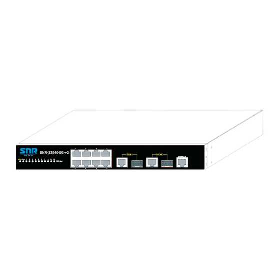
Fig 1-1 SNR-S2940-8G-v2 switch 1.1.1 Overview SNR-S2940-8G-v2 switch is 1000Mb layer 2 switch. SNR-S2940-8G-v2 provides 10 fixed ports (8 10/100Base-T fixed ports and 2 1000Mb COMBO ports). Switch with advanced intelligent and secure features, can serve ideally as distribution layer switches for the access device of campus networks, enterprise networks and IP metropolitan networks. -
Page 3: Physical Specifications
RADIUS, to ensure the port level security and block illegal users. QoS SNR-S2940-8G-v2 switch fully supports DiffServ Module. Each port provides four priority queue, WRR/SP/SWRR scheduling is also supported. SNR-S2940-8G-v2 supports the port security. Users can deploy trusted CoS, DSCP, IP precedence, port priority and modify packets’... -
Page 4: Description Of Hardware
Chapter 1 Introduction 1.3 Description of Hardware 1.3.1 Front Panel SNR-S2940-8G-v2 provides 8 10/100Base-T ports, 2 Combo ports (2 RJ-45 and 2 SFP ports), 1 Console port and 12 LEDs. The front panel of SNR-S2940-8G-v2 is shown as follow: Fig 1-2 Front Panel of SNR-S2940-8G-v2 1.3.2 Back Panel... -
Page 5: Front Panel Port Description
Combo port is linked successfully, and Port9/10(Link/Act) Flash(Green) receive/send data Combo port is not link 1.3.3.2 System Status Indicator Description Fig 1-5 SNR-S2940-8G-v2 system LED diagram Table 1-2 system indicator description Status Description On (Green) The internal power is operating normally... - Page 6 SNR-S2940-8G-v2 Installation manual Chapter 1 Introduction • SFP-SX-L transceiver 1000Base-SX SFP(850nm,MMF,550m) • SFP-LX-L transceiver 1000Base-LX SFP(1310nm, SMF, 10km or MMF, 550m) • SFP-LX-20-L transceiver 1310nm lightwave, 9/125um single mode fiber: 20km • SFP-LX-40 transceiver 9/125um single mode fiber: 40km •...
-
Page 7: Chapter 2 Hardware Installation
2.1.1.1 Dust and Particles Dust is harmful to the safe operation of SNR-S2940-8G-v2. Dust can lead to electrostatic adherence, especially likely under low relative humidity, causing poor contact of metal connectors or contacts. Electrostatic adherence will result in not only reduced product lifespan, but also increased chance of communication failures. - Page 8 SNR-S2940-8G-v2 Installation manual Chapter 2 Hardware Installation harmful gases will aggravate metal corrosion and the aging of some parts. The site should avoid harmful gases, such as SO S, NO , NH and Cl , etc. The table below details the threshold value.
- Page 9 SNR-S2940-8G-v2 Installation manual Chapter 2 Hardware Installation 2.1.1.3 Power Supply It is adopted module switch power for the switch, the input parameters of power are shown below: The AC input voltage: 100~240VAC The frequency: 50Hz ~ 60Hz Before powering on the power supply, please check the input power to ensure proper grounding of the power supply system.
-
Page 10: Installation Notice
SNR-S2940-8G-v2 Installation manual Chapter 2 Hardware Installation 2.1.1.6 Rack Configuration The dimension of the switch is designed to be mounted on a standard 19’’ rack. Please ensure good ventilation for the rack. Every device in the rack will generate heat during operation, therefore vent and fans must be provided for an enclosed rack, and devices should not be stacked closely. -
Page 11: Installation Preparation
SNR-S2940-8G-v2 Installation manual Chapter 2 Hardware Installation Do not touch the power plug and power socket. Do not place the tinder near the switch. Do not configure the switch alone in a dangerous situation. Use standard power sockets which have overload and leakage protection. -
Page 12: Installation Guide
SNR-S2940-8G-v2 Installation manual Chapter 2 Hardware Installation 2.3 Installation Guide 2.3.1 Installing the Switch Please mount the switch as below: 1. Attach the 2 brackets on the switch with screws provided in the accessory kit. Fig 2-1 Fasten the Brackets to the Switch 2. -
Page 13: Switch Grounding
The overall grounding requirements are the sum total of the above. Ground resistance value should be less than 1 ohm. The SNR-S2940-8G-v2 provides chassis grounding post in the lower rear chassis, marked as “ ”. Chassis protection grounding should be properly connected to the rack grounding connector. -
Page 14: Sfp Transceiver Installation
SNR-S2940-8G-v2 Installation manual Chapter 2 Hardware Installation SNR-S2940-8G-v2 provides a RJ45 serial console port. Fig 2-3 Connecting Console to switch The connection procedure is listed below: Find the console cable provided in the accessory kit. Attach the RJ45 end to console port of the switch. -
Page 15: Ac Power Supply Connection
Do not stare at the fiber bore when the switch is in operation. That may hurt your eyes. 2.3.6 AC Power Supply Connection SNR-S2940-8G-v2 uses the power is 220VAC. Please read the power input specification for the detailed information. AC Power supply connection procedure is described as below: 1. - Page 16 SNR-S2940-8G-v2 Installation manual Chapter 2 Hardware Installation the back panel of the switch. 2. Check the power status indicator in the front panel of the switch. The corresponding power indicator should light. Switch is self-adjustable for the input voltage. As soon as the input voltage is in the range printed on the switch surface, the switch can operate correctly.
Need help?
Do you have a question about the SNR-S2940-8G-v2 and is the answer not in the manual?
Questions and answers