Table of Contents
Advertisement
Port Configuration
CHAPTER 1 PORT CONFIGURATION ......................................1-1
....................................................................................................2-1
CHAPTER 4 ULDP FUNCTION CONFIGURATION...................4-1
Content
......................................................................1-1
...................................................................1-4
..................................................................4-6
........................................1-1
.........................................................1-3
......................................2-1
...................................................2-1
...................................2-2
...............................3-3
................................3-4
.....................................................4-1
.............................................4-2
..................................................4-5
1
Content
...................3-1
.....3-2
Advertisement
Table of Contents
Troubleshooting

Related Manuals for DCN DCRS-5650-28CT


Summary of Contents for DCN DCRS-5650-28CT
-
Page 1: Table Of Contents
Port Configuration Content Content CHAPTER 1 PORT CONFIGURATION ........1-1 1.1 I ..............1-1 NTRODUCTION TO 1.2 N ........1-1 ETWORK ONFIGURATION 1.3 P ............1-3 ONFIGURATION XAMPLE 1.4 P ..............1-4 ROUBLESHOOTING CHAPTER 2 PORT ISOLATION FUNCTION CONFIGURATION ....................2-1 2.1 I ........2-1 NTRODUCTION TO SOLATION UNCTION 2.2 T... - Page 2 Port Configuration Content ....................5-1 5.1 I LLDP F .............5-1 NTRODUCTION TO UNCTION 5.2 LLDP F ......5-2 UNCTION ONFIGURATION EQUENCE 5.3 LLDP F ............5-5 UNCTION YPICAL XAMPLE 5.4 LLDP F ...........5-6 UNCTION ROUBLESHOOTING CHAPTER 6 PORT CHANNEL CONFIGURATION....6-1 6.1 I ............6-1 NTRODUCTION TO HANNEL 6.2 P...
-
Page 3: Chapter 1 Port Configuration
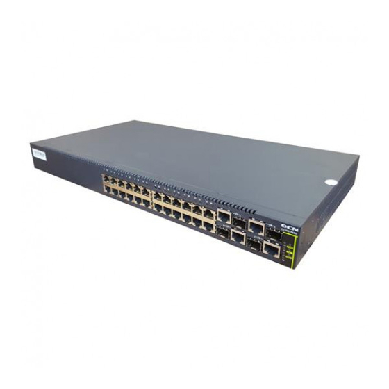
Chapter 1 Port Configuration 1.1 Introduction to Port DCRS-5650-28CT provides 24 fixed 100M electric ports and 4 fixed 1000M ports (2 1000M electric ports and 2 1000M combo ports). DCRS-5650-52CT provides 48 fixed 100M electric ports and 4 fixed 1000M ports (2 1000M electric ports and 2 1000M combo ports). - Page 4 Port Configuration Chapter 1 Port Configuration Command Explanation Port Mode shutdown Enables/Disables specified ports. no shutdown name <string> Names or cancels the name of specified no name ports. mdi { auto | across | normal } Sets the cable type for the specified port no mdi speed-duplex {auto | force10-half | force10-full...
-
Page 5: Port Configuration Example
Port Configuration Chapter 1 Port Configuration 1.3 Port Configuration Example Switch 1 0/0/7 0/0/9 0/0/27 0/0/12 0/0/8 Switch 2 Switch 3 Fig 1-1 Port Configuration Example No VLAN has been configured in the switches, default VLAN1 is used. Switch Port Property Switch1 0/0/7... -
Page 6: Port Troubleshooting
Port Configuration Chapter 1 Port Configuration Switch3(Config-If-Ethernet0/0/12)#exit 1.4 Port Troubleshooting Here are some situations that frequently occurs in port configuration and the advised solutions: Two connected fiber interfaces won’t link up if one interface is set to auto-negotiation but the other to forced speed/duplex. This is determined by IEEE 802.3. The following combinations are not recommended: enabling traffic control as well as setting multicast limiting for the same port;... -
Page 7: Chapter 2 Port Isolation Function Configuration
Port Configuration Chapter 2 Port Isolation Function Configuration Chapter 2 Port Isolation Function Configuration 2.1 Introduction to Port Isolation Function Port isolation is an independent port-based function working in an inter-port way, which isolates flows of different ports from each other. With the help of port isolation, users can isolate ports within a VLAN to save VLAN resources and enhance network security. -
Page 8: Port Isolation Function Typical Examples
Port Configuration Chapter 2 Port Isolation Function Configuration isolate-port group <WORD> switchport Add one port or a group of ports into a port interface [<ethernet>] <IFNAME> isolation group to isolate, which will become isolate-port group <WORD> isolated from the other ports in the group; switchport interface [<ethernet>]... - Page 9 Port Configuration Chapter 2 Port Isolation Function Configuration isolation is enabled on switch S1, e0/0/1 and e0/0/10 on switch S1 can not communicate with each other, while both of them can communicate with the uplink port e0/0/17. That is, the communication between any pair of downlink ports is disabled while that between any downlink port and a specified uplink port is normal.
-
Page 10: Chapter 3 Port Loopback Detection Function
Port Configuration Chapter 3 Port Loopback Detection Function Configuration Chapter 3 Port Loopback Detection Function Configuration 3.1 Introduction to Port Loopback Detection Function With the development of switches, more and more users begin to access the network through Ethernet switches. In enterprise network, users access the network through layer-2 switches, which means urgent demands for both internet and the internal layer 2 Interworking. -
Page 11: Port Loopback Detection Function Configuration Task List
Port Configuration Chapter 3 Port Loopback Detection Function Configuration 3.2 Port Loopback Detection Function Configuration Task List 1. Configure the time interval of loopback detection 2. Enable the function of port loopback detection 3. Configure the control method of port loopback detection 4.... -
Page 12: Port Loopback Detection Function Example
Port Configuration Chapter 3 Port Loopback Detection Function Configuration Enable the debug information of the function module port loopback debug loopback-detection detection. The no operation of this no debug loopback-detection command will disable debug information. Display the state and result of the loopback detection of all ports, if no show loopback-detection... -
Page 13: Port Loopback Detection Troubleshooting
Port Configuration Chapter 3 Port Loopback Detection Function Configuration connecting the switch with the outside network, the switch will notify the connected network about the existence of a loopback, and control the port on the switch to guarantee the normal operation of the whole network. The configuration task sequence of SWITCH: Switch(config)#loopback-detection interval-time 35 15 Switch(config)#interface ethernet 0/0/1... -
Page 14: Chapter 4 Uldp Function Configuration
Port Configuration Chapter 4 ULDP Function Configuration Chapter 4 ULDP Function Configuration 4.1 Introduction to ULDP Function Unidirectional link is a common error state of link in networks, especially in fiber links. Unidirectional link means that only one port of the link can receive messages from the other port, while the latter one can not receive messages from the former one. -
Page 15: Uldp Configuration Task Sequence
Port Configuration Chapter 4 ULDP Function Configuration Interface Converter) or interfaces have problems, software problems, hardware becomes unavailable or operates abnormally. Unidirectional link will cause a series of problems, such as spinning tree topological loop, broadcast black hole. ULDP (Unidirectional Link Detection Protocol) can help avoid disasters that could happen in the situations mentioned above. - Page 16 Port Configuration Chapter 4 ULDP Function Configuration uldp enable Globally enable disable ULDP uldp disable function. 2. Enable ULDP function on a port Command Explanation Port configuration mode uldp enable Enable or disable ULDP function on a uldp disable port. 3.
- Page 17 Port Configuration Chapter 4 ULDP Function Configuration Configure the interval of Recovery reset, uldp recovery-time <integer> ranging from 30 to 86400 seconds. The no uldp recovery-time <integer> value is 0 second by default. 8. Reset the port shut down by ULDP Command Explanation Global...
-
Page 18: Uldp Function Typical Examples
Port Configuration Chapter 4 ULDP Function Configuration 4.3 ULDP Function Typical Examples Switch A g0/0/1 g0/0/2 g0/0/3 g0/0/4 Switch B Fig 4-3 Fiber Cross Connection In the network topology in Graph, port g0/0/1 and port g0/0/2 of SWITCH A as well as port g0/0/3 and port g0/0/4 of SWITCH B are all fiber ports. -
Page 19: Uldp Troubleshooting
Port Configuration Chapter 4 ULDP Function Configuration notification information on the CRT terminal of PC1. %Oct 29 11:09:50 2007 A unidirectional link is detected! Port Ethernet0/0/1 need to be shutted down! %Oct 29 11:09:50 2007 Unidirectional port Ethernet0/0/1 shut down! %Oct 29 11:09:50 2007 A unidirectional link is detected! Port Ethernet0/0/2 need to be shutted down! %Oct 29 11:09:50 2007 Unidirectional port Ethernet0/0/2 shutted down! - Page 20 Port Configuration Chapter 4 ULDP Function Configuration ULDP does not compact with similar protocols of other vendors, which means users can not use ULDP on one end and use other similar protocols on the other end. ULDP function is disabled by default. After globally enabling ULDP function, the debug switch can be enabled simultaneously to check the debug information.
-
Page 21: Chapter 5 Lldp Function Operation Configuration
Port Configuration Chapter 5 LLDP Function Operation Configuration Chapter 5 LLDP Function Operation Configuration 5.1 Introduction to LLDP Function Link Layer Discovery Protocol (LLDP) is a new protocol defined in 802.1ab. It enables neighbor devices to send notices of their own state to other devices, and enables all ports of every device to store information about them. -
Page 22: Lldp Function Configuration Task Sequence
Port Configuration Chapter 5 LLDP Function Operation Configuration trace the change and condition of topology, but most of them can reach layer-three and classify the devices into all IP subnets at best. This kind of data are very primitive, only referring to basic events like the adding and removing of relative devices instead of details about where and how these devices operate with the network. - Page 23 Port Configuration Chapter 5 LLDP Function Operation Configuration 3. Configure the operating state of port LLDP Command Explanation Port Mode Configure operating state lldp mode (send|receive|both|disable) port LLDP. 4. Configure the intervals of LLDP updating messages Command Explanation Global Mode Configure intervals LLDP...
- Page 24 Port Configuration Chapter 5 LLDP Function Operation Configuration Enable or disable the Trap function of lldp trap <enable|disable> the port. 9. Configure the optional information-sending attribute of the port Command Explanation Port Configuration Mode Configure optional lldp transmit optional tlv [portDesc] information-sending attribute of the [sysName] [sysDesc] [sysCap] port as the option value of default...
-
Page 25: Lldp Function Typical Example
Port Configuration Chapter 5 LLDP Function Operation Configuration debug lldp Enable or disable the DEBUG switch. no debug lldp debug lldp packets interface ethernet Enable disable DEBUG <IFNAME> packet-receiving and sending function no debug lldp packets interface ethernet in port or global mode. <IFNAME>... -
Page 26: Lldp Function Troubleshooting
Port Configuration Chapter 5 LLDP Function Operation Configuration 5.4 LLDP Function Troubleshooting LLDP function is disabled by default. After enabling the global switch of LLDP, users can enable the debug switch “debug lldp” simultaneously to check debug information. Using “show” function of LLDP function can display the configuration information in global or port configuration mode. -
Page 27: Chapter 6 Port Channel Configuration
Port Configuration Chapter 6 Port Channel Configuration Chapter 6 Port Channel Configuration 6.1 Introduction to Port Channel To understand Port Channel, Port Group should be introduced first. Port Group is a group of physical ports in the configuration level; only physical ports in the Port Group can take part in link aggregation and become a member port of a Port Channel. -
Page 28: Port Channel Configuration Task List
Port Configuration Chapter 6 Port Channel Configuration For Port Channel to work properly, member ports of the Port Channel must have the same properties as follows: All ports are in full-duplex mode. All Ports are of the same speed. All ports are Access ports and belong to the same VLAN or are all TRUNK ports. If the ports are TRUNK ports, then their “Allowed VLAN”... -
Page 29: Port Channel Examples
Port Configuration Chapter 6 Port Channel Configuration no port-group <port-group-number> 3. Enter port-channel configuration mode. Command Explanation Global Mode interface port-channel Enters port-channel configuration mode. <port-channel-number> 6.3 Port Channel Examples Scenario 1: Configuring Port Channel in LACP. SwitchA SwitchB Fig 6-2 Configuring Port Channel in LACP The switches in the description below are all switch and as shown in the figure, ports 1, 2, 3, 4 of SwitchA are access ports that belong to VLAN1. - Page 30 Port Configuration Chapter 6 Port Channel Configuration SwitchB (config)#interface eth 0/0/6 SwitchB (Config-If-Ethernet0/0/6)#port-group 2 mode passive SwitchB (Config-If-Ethernet0/0/6)#exit SwitchB (config)#interface eth 0/0/8-10 SwitchB (Config-If-Port-Range)#port-group 2 mode passive SwitchB (Config-If-Port-Range)#exit SwitchB (config)#interface port-channel 2 SwitchB (Config-If-Port-Channel2)# Configuration result: Shell prompts ports aggregated successfully after a while, now ports 1, 2, 3, 4 of Switch A form an aggregated port named “Port-Channel1”, ports 6, 8, 9, 10 of Switch B forms an aggregated port named “Port-Channel2”;...
-
Page 31: Port Channel Troubleshooting
Port Configuration Chapter 6 Port Channel Configuration SwitchA (Config-If-Ethernet0/0/2)#port-group 1 mode on SwitchA (Config-If-Ethernet0/0/2)#exit SwitchA (config)#interface ethernet 0/0/3 SwitchA (Config-If-Ethernet0/0/3)#port-group 1 mode on SwitchA (Config-If-Ethernet0/0/3)#exit SwitchA (config)#interface ethernet 0/0/4 SwitchA (Config-If-Ethernet0/0/4)#port-group 1 mode on SwitchB (config)#port-group 2 SwitchB (config)#interface ethernet 0/0/6 SwitchB (Config-If-Ethernet0/0/6)#port-group 2 mode on SwitchB (Config-If-Ethernet0/0/6)#exit SwitchB (config)#interface ethernet 0/0/8-10... - Page 32 Port Configuration Chapter 6 Port Channel Configuration Once the port-channel created, all port configurations can only be done on the port-channel port. LACP should be mutually exclusive to Security and 802.1x ports. If a port has already enabled these two protocols, it won’t be allowed to use LACP. The following prompt will show up if there is any incorrect configuration while creating a PortChannel.
-
Page 33: Chapter 7 Jumbo Configuration
Port Configuration Chapter 7 Jumbo Configuration Chapter 7 Jumbo Configuration 7.1 Introduction to Jumbo So far the Jumbo (Jumbo Frame) has not reach a determined standard in the industry (including the format and length of the frame). Normally frames sized within 1519-9000 should be considered jumbo frame.
Need help?
Do you have a question about the DCRS-5650-28CT and is the answer not in the manual?
Questions and answers