Table of Contents
Advertisement
Quick Links
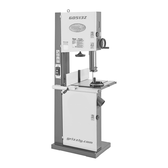
MODEL G0513Z
17" 2 HP BANDSAW
MANUAL INSERT
For Machines Mfd. Since 02/24
and Owner's Manual Revised 08/22
The Model G0513Z is the same machine as the Model G0513A40 except for the 40th Anniversary paint
scheme. Except for the differences noted in this insert, all other content in the Model G0513 Series owner's
manual applies to this machine.
: To reduce the risk of serious injury, you MUST read and understand this insert—and
the entire Model G0513 Series manual—BEFORE assembling, installing, or operating this machine!
If you have any further questions about this manual insert or the differences between the Model G0513Z and
the Model G0513A40, contact our Technical Support at (570) 546-9663 or email techsupport@grizzly.com.
COPYRIGHT © MARCH, 2024 BY GRIZZLY INDUSTRIAL, INC.
WARNING: NO PORTION OF THIS MANUAL MAY BE REPRODUCED IN ANY SHAPE
OR FORM WITHOUT THE WRITTEN APPROVAL OF GRIZZLY INDUSTRIAL, INC.
#KS23100 PRINTED IN TAIWAN
***Keep for Future Reference***
Advertisement
Table of Contents

Related Manuals for Grizzly G0513Z


Summary of Contents for Grizzly G0513Z
- Page 1 Model G0513 Series manual—BEFORE assembling, installing, or operating this machine! If you have any further questions about this manual insert or the differences between the Model G0513Z and the Model G0513A40, contact our Technical Support at (570) 546-9663 or email techsupport@grizzly.com.
- Page 2 MACHINE DATA SHEET Customer Service #: (570) 546-9663 · To Order Call: (800) 523-4777 · Fax #: (800) 438-5901 MODEL G0513Z 17" 2 HP BANDSAW Product Dimensions: Weight................................309 lbs. Width (side-to-side) x Depth (front-to-back) x Height................32 x 32 x 73 in.
- Page 3 The information contained herein is deemed accurate as of 2/28/2024 and represents our most recent product specifications. Model G0513Z PAGE 2 OF 3 Due to our ongoing improvement efforts, this information may not accurately describe items previously purchased. Model G0513Z (Mfd. Since 02/24)
- Page 4 PARTS We do our best to stock replacement parts when possible, but we cannot guarantee that all parts shown are available for purchase. Call (800) 523-4777 or visit www.grizzly.com/parts to check for availability. Main 11-1 176 39 64 88 82-6...
- Page 5 HEX BOLT M6-1 X 20 P0513Z058 WHEEL BRUSH P0513Z175 HEX BOLT M6-1 X 20 P0513Z059 HEX BOLT M6-1 X 25 P0513Z176 BUSHING BUY PARTS ONLINE AT GRIZZLY.COM! Model G0513Z (Mfd. Since 02/24) Scan QR code to visit our Parts Store.
- Page 6 P0513Z115 GEAR PLATE P0513Z163 LOCK WASHER 8MM P0513Z116 LOCK NUT M8-1.25 P0513Z196 STEEL BALL 5MM P0513Z117 PHLP HD SCR M4-.7 x 6 BUY PARTS ONLINE AT GRIZZLY.COM! Model G0513Z (Mfd. Since 02/24) Scan QR code to visit our Parts Store.
- Page 7 P0513Z230 FENDER WASHER 8MM P0513Z216 MOVING PLATE P0513Z231 ADJ HANDLE 65L, M8-1.25 X 25 P0513Z217 FLAT WASHER 6MM P0513Z232 FENCE SCALE 18-1/2" BUY PARTS ONLINE AT GRIZZLY.COM! Model G0513Z (Mfd. Since 02/24) Scan QR code to visit our Parts Store.
- Page 8 Upper Blade Guides & Miter Gauge 157A 138-1 173-5 173-4 173-2 173-6 173-9 173-3 173-1 173-8 173-7 BUY PARTS ONLINE AT GRIZZLY.COM! Model G0513Z (Mfd. Since 02/24) Scan QR code to visit our Parts Store.
- Page 9 P0513Z160 LOCK COLLAR P0513Z198 CAP SCREW M5-.8 X 12 P0513Z161 THREADED BUSHING P0513Z199 FLAT WASHER 5MM P0513Z162 CAP SCREW M8-1.25 X 20 BUY PARTS ONLINE AT GRIZZLY.COM! Model G0513Z (Mfd. Since 02/24) Scan QR code to visit our Parts Store.
- Page 10 DO NOT REPRODUCE OR CHANGE THIS ARTWORK manual BEFORE using WITHOUT WRITTEN APPROVAL! Grizzly will not accept labels changed without approval. machine. artwork changes are required, contact us immediately at manuals@grizzly.com. To get a new manual, call (800) 523-4777 or go to •...
- Page 11 WARRANTY & RETURNS Grizzly Industrial, Inc. warrants every product it sells for a period of 1 year to the original purchaser from the date of purchase. This warranty does not apply to defects due directly or indirectly to misuse, abuse, negligence, accidents, repairs or alterations or lack of maintenance.
- Page 13 G0513X2, G0513X2BF, Only COPYRIGHT © NOVEMBER, 2012 BY GRIZZLY INDUSTRIAL, INC., REVISED AUGUST, 2022 (MN) WARNING: NO PORTION OF THIS MANUAL MAY BE REPRODUCED IN ANY SHAPE OR FORM WITHOUT THE WRITTEN APPROVAL OF GRIZZLY INDUSTRIAL, INC. (FOR MACHINES MFD. SINCE 08/22) #TS15097 PRINTED IN TAIWAN...
- Page 14 This manual provides critical safety instructions on the proper setup, operation, maintenance, and service of this machine/tool. Save this document, refer to it often, and use it to instruct other operators. Failure to read, understand and follow the instructions in this manual may result in fire or serious personal injury—including amputation, electrocution, or death.
-
Page 15: Table Of Contents
Table of Contents INTRODUCTION ..........2 Ripping ............53 Contact Info............ 2 Crosscutting ..........53 G0513 Series Combination Manual ....2 Resawing ............. 54 Manual Accuracy ........... 2 Cutting Curves ..........56 Controls & Components ......... 3 Stacked Cuts..........56 G0513 Series Combination Data Sheet .. -
Page 16: Introduction
ID label. This will help us help you faster. tions, specifications, drawings, and photographs in this manual. Sometimes we make mistakes, but Grizzly Technical Support our policy of continuous improvement also means that sometimes the machine you receive is 1815 W. -
Page 17: Controls & Components
Controls & Model G0513X2BF Components To reduce your risk of serious injury, read this entire manual BEFORE using machine. Refer to the following figures and descriptions to Figure 2. Control panel with master power become familiar with the basic controls and com- switch and disabling key. - Page 18 Front Controls Rear Controls Figure 3. Front controls Figure 4. Rear controls (G0513X2BF shown). (G0513X2BF shown). A. Blade Tension Scale: Displays blade tension Wheel Cover Lock Knobs: Secure the using numbers 1–8. For reference only—after wheel covers. proper tension for particular blade has been G.
-
Page 19: G0513 Series Combination Data Sheet
G0513 Series Combination Data Sheet Customer Service #: (570) 546-9663 · To Order Call: (800) 523-4777 · Fax #: (800) 438-5901 MODEL G0513 SERIES 17" BANDSAWS Model Number G0513 G0513A40 G0513X2 G0513X2BF Product Dimensions Weight 266 lbs. 309 lbs. 325 lbs. 357 lbs. - Page 20 Model Number G0513 G0513A40 G0513X2 G0513X2BF Cutting Capacities Max. Cutting Height ⁄ " 12 " Max Cutting Width (Left of ⁄ " ⁄ " ⁄ " Blade) Max Cutting Width (Left of ⁄ " ⁄ " 15" Blade) w/Fence Max Cutting Width (Left of ⁄...
-
Page 21: Section 1: Safety
SECTION 1: SAFETY For Your Own Safety, Read Instruction Manual Before Operating This Machine The purpose of safety symbols is to attract your attention to possible hazardous conditions. This manual uses a series of symbols and signal words intended to convey the level of impor- tance of the safety messages. - Page 22 WEARING PROPER APPAREL. Do not wear FORCING MACHINERY. Do not force machine. clothing, apparel or jewelry that can become It will do the job safer and better at the rate for entangled in moving parts. Always tie back or which it was designed. cover long hair.
-
Page 23: Additional Safety For Bandsaws
Additional Safety for Bandsaws Serious cuts, amputation, or death can occur from contact with the moving saw blade during operation or if blade breakage occurs. Serious injury or death can also occur from getting fingers, hair, or clothing entangled in moving parts if the machine is operated while the doors are open. -
Page 24: Section 2: Power Supply
SECTION 2: POWER SUPPLY Availability The full-load current is not the maximum amount of amps that the machine will draw. If the machine Before installing the machine, consider the avail- is overloaded, it will draw additional amps beyond ability and proximity of the required power supply the full-load rating. - Page 25 Circuit Requirements for 220V These machines are prewired to operate on a power supply circuit that has a verified ground and meets the following requirements: Model Number G0513, G0513A40, G0513X2 G0513X2BF Circuit Requirements For 220V Operation: Nominal Voltage 208V, 220V, 230V, 240V Cycle 60 Hz Phase...
- Page 26 Grounding Requirements for 110V: The plug specified under “Circuit Requirements for 110V Operation” on the previous page has a grounding prong that must be attached to the equipment- grounding wire inside the specified power cord. The plug must only be inserted into a matching receptacle (see Figure 6) that is properly installed and grounded in accordance with all local codes and ordinances.
-
Page 27: Section 3: Setup
IMPORTANT: Save all packaging materials until you are completely satisfied with the machine and have resolved any issues between Grizzly or the shipping agent. You MUST have the original pack- aging to file a freight claim. It is also extremely helpful if you need to return your machine later. -
Page 28: Hardware Recognition Chart
Hardware Recognition Chart USE THIS CHART TO MATCH UP HARDWARE DURING THE INVENTORY AND ASSEMBLY PROCESS. Flat Head Screw -14- G0513 Series Bandsaws (Mfd. Since 08/22) -
Page 29: Inventory
Inventory The following is a list of items shipped with your machine. Before beginning setup, lay these items out and inventory them. If any non-proprietary parts are missing (e.g. a nut or a washer), we will gladly replace them; or for the sake of expediency, replacements can be obtained at your local hardware store. - Page 30 G0513A40 Inventory (Figures 9–10) A. Bandsaw (not shown) ......... 1 B. Table ............1 C. Miter Gauge ..........1 D. Rear Rail ............ 1 E. Resaw Fence ..........1 Fence Assembly ......... 1 G. Drift Bar ............1 —Fender Washer 8mm ......1 —Adjustable Handle ........
- Page 31 G0513X2 Shipping Inventory (Figures 11–12) A. Bandsaw (not shown) ......... 1 B. Table ............1 C. Miter Gauge ..........1 D. Rear Rail ............ 1 E. Resaw Fence ..........1 Fence Assembly ......... 1 G. Guide Post Handwheel....... 1 H. Front Rail ............ 1 Hardware &...
- Page 32 G0513X2BF Inventory (Figures 13–14) A. Bandsaw (not shown) ......... 1 B. Table ............1 C. Miter Gauge ..........1 D. Front Rail ............ 1 E. Resaw Fence ..........1 Fence Assembly ......... 1 G. Guide Post Handwheel....... 1 Hardware & Tools (Not Shown) •...
-
Page 33: Cleanup
Cleanup Gasoline and petroleum products have low flash The unpainted surfaces of your machine are points and can explode coated with a heavy-duty rust preventative that or cause fire if used to prevents corrosion during shipment and storage. clean machinery. Avoi d This rust preventative works extremely well, but it u sing t h e s e p r o d u c t s will take a little time to clean. -
Page 34: Site Considerations
Site Considerations Lifting & Placing Bandsaw Floor Load Refer to the Machine Data Sheet for the weight and footprint specifications of your machine. Some residential floors may require additional HEAVY LIFT! reinforcement to support both the machine and Straining or crushing injury operator. -
Page 35: Anchoring To Floor
Anchoring to Floor Using Forklift & Wood Blocks Use a forklift to move the crate to a prepared location, then remove the crate from the ship- ping pallet. Number of Mounting Holes ......4 Diameter of Mounting Hardware ....⁄ "... -
Page 36: Assembly
Assembly Loosen blade tension by rotating quick- release tension lever clockwise, as shown in Figure 22. The machine must be fully assembled before it can be operated. Before beginning the assembly process, refer to Needed for Setup and gather all listed items. To ensure the assembly process goes smoothly, first clean any parts that are cov- Loosen Tighten... - Page 37 Models G0513, G0513A40 & G0513X2 10. Attach rear rail to table with (2) M6-1 x 16 cap The table is heavy and requires two people screws, as shown in Figure 24. to lift it onto the trunnions. Remove the saw blade to make table installation easier.
- Page 38 Model G0513X2BF 13. Pull fence handle up and place fence assem- bly on front rail (see Figures 26–27). 16. Attach rail plates to front rail with (3) M6-1 x 20 cap screws, 6mm lock washers, and 6mm flat washers (see Figure 28). Front Rail Rail Plate Fence...
- Page 39 Models G0513A40, G0513X2 & 20. Install fence on left-hand side of blade. G0513X2BF 21. Place fence flush against bandsaw blade 24. Place 8mm flat washer on locking handle (see Figure 30). (see Figure 32), slide it through hole in fence, then thread moving plate onto end of locking handle threads.
-
Page 40: Dust Collection
Dust Collection Model G0513A40 26. Insert adjustable handle with fender washer through the back of resaw fence (see Figure 34). DO NOT operate this bandsaw without an Resaw Fence adequate dust collection system. This saw creates substantial amounts of wood dust while operating. -
Page 41: Adjustment Overview
Adjustment Bandsaw wheels are either flat or crowned and both shapes track differently. This bandsaw has Overview crowned wheels. As the wheels spin, a properly tracking blade naturally tracks at the center of the wheel (see Figure 37). The bandsaw is one of the most versatile wood- working machines. - Page 42 To adjust blade tracking: DISCONNECT MACHINE FROM POWER! The wheels may have sharp edges, and the blade teeth may extend beyond the edge, Adjust upper and lower blade guides away creating a laceration hazard. Be careful from blade, and raise upper guides approxi- when turning the wheels by hand.
-
Page 43: Power Cord Connection (G0513X2Bf)
Power Cord Loosen the right strain relief on the junction box, then feed the cord into the box with Connection enough slack in the wires to make the con- nections. (G0513X2BF) Re-tighten the strain relief around the cord. Tug on it to make sure the wires inside the box will not move. -
Page 44: Test Run
Test Run To test run machine: Clear all setup tools away from machine. Once assembly is complete, test run the machine Connect machine to power supply. to ensure it is properly connected to power and safety components are functioning correctly. Turn machine ON, verify motor operation, and then turn machine OFF. - Page 45 G0513X2BF The Test Run consists of verifying the following: Power Switch 1) The motor powers up and runs correctly, 2) the safety feature of the OFF button works correctly, and 3) the foot brake pedal works correctly. ON Button OFF Button Serious injury or death can result from using this machine BEFORE understanding its controls and related safety information.
-
Page 46: Tensioning Blade
Tensioning Blade The Flutter Method Using the flutter method, you intentionally loosen the blade until it just passes the point of being too loose (when it begins to flutter). Then you A properly tensioned blade is essential for mak- gradually tighten the blade until proper tension is ing accurate cuts, maximizing blade life, and reached. -
Page 47: Fine Tune Tracking
Fine Tune Tracking The Deflection Method The deflection method is much more subjective than the flutter method. Each blade will deflect differently and every user will determine what During setup, the blade was tracked without the "moderate pressure" means. The following are machine connected to power (refer to Page 27). -
Page 48: Adjusting Blade Support Bearings
Adjusting Blade Position support bearing approximately 0.016" away from back of blade, as illustrat- Support Bearings ed in Figure 47. Note: The main purpose of this adjustment is to prevent the blade from being pushed The support bearings are positioned behind the backward far enough that the blade guides blade near the blade guides and prevent the blade will contact (and ruin) the "tooth set"... -
Page 49: Adjusting Blade Guides
Adjusting Blade To adjust the upper blade guides: Guides DISCONNECT MACHINE FROM POWER! Loosen the thumb screws shown in Figure 48. The blade guides provide side-to-side support to keep the blade straight while cutting. These Blade Guides guides are adjustable in two ways—forward-and- back and side-to-side. - Page 50 Loosen the guide block cap screw shown in Figure 50. Make sure that the blade teeth will not con- tact the guides when the blade is against the rear support bearing during the cut or the blade teeth will be damaged. 0.004"...
- Page 51 Models G0513X2 & G0513X2BF Loosen the lateral rod cap screw and slide the guide block to position the blade guides Tools Needed approximately 0.016" behind the blade gul- Hex Wrench 5mm ..........1 lets, as illustrated in Figure 54. Feeler Gauges 0.004", 0.016" ....1 Each Note: The 0.016"...
-
Page 52: Aligning Table
Aligning Table Straightedge To ensure cutting accuracy, the table should be aligned so that the miter slot is parallel to the bandsaw blade, and that the table is perpendicu- lar (front to back) to the blade. These procedures work best with a wide ( ⁄... -
Page 53: Aligning Fence
Aligning Fence Adjusting Table Perpendicular to Blade DISCONNECT MACHINE FROM POWER! To ensure cutting accuracy, the fence should be Place a square on the table and against the aligned parallel with the blade. This is achieved back of the blade, as shown in Figure 57. The by aligning the fence to the miter slot after miter table should be perpendicular to the back of slot parallelism is properly adjusted, as instructed... -
Page 54: Adjusting Positive Stop
Adjust the fence face parallel with the edge of the miter slot, as shown in Figure 61. G0513A40 Fence Cap Screws Figure 59. G0513A40 fence cap screws. Figure 61. Example of fence parallel with miter Adjust the fence face parallel with the edge of slot. -
Page 55: Calibrating Miter Gauge
Raise the guide post and place a machinist’s To calibrate the miter gauge: square on the table next to the side of the blade, as illustrated in Figure 62. Adjust the DISCONNECT MACHINE FROM POWER! table square with the blade, then secure it with the table tilt lock lever. -
Page 56: Section 4: Operations
Read books/magazines or get formal training before beginning any proj- ects. Regardless of the content in this sec- tion, Grizzly Industrial will not be held liable for accidents caused by lack of training. -42- G0513 Series Bandsaws (Mfd. Since 08/22) -
Page 57: Disabling & Locking Switch (G0513, G0513A40, G0513X2)
Disabling & Locking Disabling & Locking Switch (G0513, Switch (G0513X2BF) G0513A40, G0513X2) The power switch can be disabled and locked by removing the key, as shown. Locking the switch The switch can be disabled and locked by insert- in this manner can prevent unauthorized opera- ing a padlock through the power button, as tion of the machine, which is especially important shown in Figure 64. -
Page 58: General Overview
General Overview Workpiece Inspection The bandsaw is one of the most versatile wood cutting tools in the shop. It is capable of perform- Some wood workpieces are not safe to cut or may ing many different cutting functions including: require modification before they are safe to cut. Straight Cuts Before cutting wood, get in the habit of •... -
Page 59: Tilting Table
Tilting Table Models G0513X2 & G0513X2BF Table Tilt Scale To make beveled cuts, the table can be tilted as indicated below: Model Tilt Specifications G0513, G0513A40 ....10° left, 45° right Table Tilt G0513X2, G0513X2BF ....5° left, 45° right Lever A table tilt scale with pointer is provided on the trunnion, and a positive stop is provided for quick-... -
Page 60: Setting Upper Blade Guide Height
Setting Upper Blade Blade Selection Guide Height Selecting the right blade requires a knowledge of the various blade characteristics to match the When cutting, the blade guides must always be blade with the particular cutting operation. positioned so they just clear (no more than ⁄... - Page 61 Blades will vary slightly even in the same length because of how they are welded. Refer to the Accessories section later in this manual for blade replacements from Grizzly. Blade Width Measured from the back of the blade to the tip of...
- Page 62 Tooth Pitch Blade Material Measured as TPI (teeth per inch), tooth pitch Bandsaw blades must meet two requirements: determines the number of teeth. More teeth per flexibility and hardness. The flexibility of a blade inch (fine pitch) will cut slower, but smoother; while allows it to travel on the wheel as a band, while fewer teeth per inch (coarse pitch) will cut rougher, hardness allows the teeth to cut and hold an...
-
Page 63: Blade Selection Chart
Blade Selection Chart Use the blade selection chart below as a general guide when selecting a blade for your operation. Blade Width Cutting Operation Narrow ( ⁄ " – ⁄ ") Medium ( ⁄ "– ⁄ ") Wide ( ⁄ "–... -
Page 64: Blade Care & Break-In
Blade Care & Blade Breakage Break-In Many conditions may cause a bandsaw blade to break. Blade breakage is unavoidable in some Blade Care cases, since it is the natural result of the peculiar stresses that bandsaw blades must endure. A bandsaw blade is a thin piece of steel that is subjected to tremendous strain. -
Page 65: Changing Blade
Changing Blade Open the upper and lower wheel covers, and with gloved hands, slide the blade off of both wheels. Rotate the blade 90˚ and slide it through the slot in the table to remove it. Disconnect bandsaw from Installing Blade power BEFORE changing blade. -
Page 66: Changing Blade Speed
Changing Blade Refer to Figure 77 to locate the correct V-belt position for the desired blade speed and Speed move the V-belt to the indicated pulleys. The blade speed can be adjusted to 1700 or 3500 FPM. Speed adjustments are made by moving the BANDSAW WHEEL V-belt position on the motor and wheel pulleys. -
Page 67: Ripping
Ripping Crosscutting "Ripping" means cutting with the grain of the Crosscutting is the process of cutting across the wood stock. For plywood and other processed grain of wood. For plywood and other processed wood, ripping simply means cutting down the wood, crosscutting simply means cutting across length of the workpiece. -
Page 68: Resawing
Resawing Use widest blade the bandsaw will accept. Install resaw fence (see Figure 82), set it to desired width of cut, and lock it in place. "Resawing" means cutting the thickness of a board into two or more thinner boards (see Figure 81 for an example). - Page 69 Using Drift Bar Blade Model G0513A40 includes a drift bar that installs Blade Guides Drift on the resaw fence and is designed to help reduce blade lead by creating a pivot point that provides Blade more control during resaw operations. 1/4"...
-
Page 70: Cutting Curves
Cutting Curves Stacked Cuts When cutting curves, simultaneously feed and One of the benefits of a bandsaw is its ability to turn the stock carefully so the blade follows the cut multiple copies of a particular shape by stack- layout line without twisting. If curves are sharp or ing a number of workpieces together. -
Page 71: Section 5: Accessories
Grizzly bandsaws: serious personal injury or machine damage. To reduce this risk, only install accessories • G0457 • G0531B recommended for this machine by Grizzly. • G0513X • G0555X • G0513X2 •... - Page 72 Gun Treatment 12 Oz. Spray ® Figure 92. D2057A SHOP FOX ® Mobile Base. Figure 90. Recommended products for protect- ing unpainted cast iron/steel part on machinery. www.grizzly.com 1-800-523-4777 order online at or call -58- G0513 Series Bandsaws (Mfd. Since 08/22)
- Page 73 T26544—LED Light w/Mag Base & Flex Arm D2272—Tilting Roller Stand This high intensity LED flashlight is ultra-bright Adjusts from 26" to 44", 0º-45º. 150 lb. capacity. and zoomable, allowing you to focus or disperse D2273—Single Roller Stand the light. Has three modes: high beam, low beam, Adjusts from 26 ⁄...
- Page 74 SB1094—5 HP Cyclone Dust Collector D4206—Clear Flexible Hose 4" x 10' The Model SB1094 features a 5 HP motor, a D4256—45° Elbow 4" whopping 2399 CFM of airflow capacity, and a D4216—Black Flexible Hose 4" x 10' 60-gallon collection capacity. It's packed with W1034—Heavy-Duty Clear Flex Hose 4"...
-
Page 75: Section 6: Maintenance
SECTION 6: MAINTENANCE Cleaning & Protecting To reduce risk of shock or accidental startup, always disconnect machine from power before adjustments, Cleaning the bandsaw is relatively easy. Vacuum maintenance, or service. excess wood chips and sawdust, and wipe off the remaining dust with a dry cloth. - Page 76 Using a rag and mineral spirits, wipe off any Apply a thin coat of lubricant to the tension existing grease and sawdust build-up on the adjustment assembly and tension lever cam rack (see Figure 99). (see Figure 100). Adjustment Assembly Rack Exposed for Lubrication Figure 99.
-
Page 77: Section 7: Service
SECTION 7: SERVICE Review the troubleshooting procedures in this section if a problem develops with your machine. If you need replacement parts or additional help with a procedure, call our Technical Support. Note: Please gather the serial number and manufacture date of your machine before calling. Troubleshooting Motor &... - Page 78 Symptom Possible Cause Possible Solution Machine has 1. Motor or component loose. 1. Replace damaged/missing bolts/nuts; tighten if loose. vibration or 2. Replace blade (Page 51). 2. Blade weld at fault/teeth broken. noisy operation. 3. Replace warped/bent blade (Page 51); resharpen dull 3.
- Page 79 Symptom Possible Cause Possible Solution Miter bar binds 1. Miter slot dirty or gummed up. 1. Carefully clean miter slot. in miter slot. 2. Miter bar bent. 2. Replace. Blade tracks 1. Tracking is not adjusted properly. 1. Adjust tracking (Page 33). incorrectly 2.
-
Page 80: V-Belt Service
V-Belt Service To replace the V-belt: DISCONNECT BANDSAW FROM POWER! Checking V-Belt Open both wheel covers, and remove the blade (refer to Changing Blade on Page 51). To ensure optimum power transmission from the motor to the blade, the V-belt must be in good Unthread the lower wheel mount bolt shown condition and properly tensioned. -
Page 81: Blade Lead
Blade Lead Skewing Fence Cut a straight and parallel wood board approximately ⁄ " thick x 3" wide x 16" long. "Blade Lead" means that the blade does not cut Tip: Cut your board out of a new piece straight when using the fence or miter gauge (see ⁄... -
Page 82: Adjusting Wheel Brush
Adjusting Wheel Adjusting Quick- Brush Release Tension Lever The lower wheel has a brush, as shown in Figure The quick-release tension lever was set up at the 107, that is designed to sweep sawdust off the factory for use with the pre-installed 131 ⁄... -
Page 83: Adjusting Guide Post Travel
Adjusting Guide — If there is no gap between the square and the guide post along its full length, no Post Travel adjustments need to be made. Proceed to the next procedure. — If there is a gap between the square and The guide post assembly should remain paral- the guide post, the guide post is not paral- lel with the blade front-to-back and side-to-side... - Page 84 Checking/Adjusting Guide Post Loosen the four screws shown in Figure 110 on the previous page enough to fit metal Parallel with Blade Front-to-Back shims between the frame and the guide post DISCONNECT MACHINE FROM POWER! bracket (see Figure 112). Loosen the guide post lock knob, lower the —...
-
Page 85: Aligning Wheels
Aligning Wheels ⁄ " Components and Hardware Needed: 56" Long 2x4 ............. 1 Tools Needed: 17" Hex Wrenches 4, 6mm .........1 Ea Wrench 13mm ........... 1 Tape Measure ............ 1 Coplanarity Gauge (see Figure 113) ....1 Straightedge ............Fine Ruler ............1 Wheel alignment is one of the most critical factors for optimal performance from your bandsaw. - Page 86 — If the wheels are coplanar (Figure 116, A), the straightedge will evenly touch the top and bottom of both wheels. Not Coplanar — If the wheels are not coplanar (Figure Coplanar 116, B), place the straightedge on the lower wheel first (ensuring that it touches both the top and bottom rim), then adjust Solution: the upper wheel tracking knob to make the...
-
Page 87: Magnetic Brake Adjustment (G0513X2Bf)
Magnetic Brake When the wheels are coplanar, place a mark on each wheel where you held the straight- Adjustment edge. This assures repeated accuracy every time you adjust your wheels. (G0513X2BF) Note: When wheels are properly coplanar, the blade may not be centered on the crown of the wheel, but it will be balanced. -
Page 88: Section 8: Wiring
Technical Support at (570) 546-9663. The photos and diagrams included in this section are best viewed in color. You can view these pages in color at www.grizzly.com. -74- G0513 Series Bandsaws (Mfd. Since 08/22) -
Page 89: G0513, G0513A40 & G0513X2 Wiring Diagram
G0513, G0513A40 & G0513X2 Wiring Diagram Ground Power Switch Neutral (viewed from behind) 110 VAC L5-30 Plug (As Recommended) Ground Ground 6-15 Plug (As Recommended) Rewired to 110V Motor wired for 220V Start Capacitor Capacitor 40uF 300M Ground 250V 250V Motor rewired for 110V Start Capacitor... -
Page 90: G0513X2Bf Wiring Diagram
G0513X2BF Wiring Diagram Ground Power Supply Junction Box Ground Ground 220V 6-15 Plug (As Recommended) Control Panel Magnetic Switch Assembly (Viewed from Behind) Foot Brake Switch Power L1/1 L2/3 L3/5 NO13 Contactor SDE MA-18 NC15 NC16 T1/2 T2/4 T3/6 NO14 OL Relay SDE RA-20 Set at... -
Page 91: Section 9: Parts
SECTION 9: PARTS We do our best to stock replacement parts when possible, but we cannot guarantee that all parts shown are available for purchase. Call (800) 523-4777 or visit www.grizzly.com/parts to check for availability. G0513 & G0513A40 Main 11-1... - Page 92 FLAT WASHER 6MM P0513175 HEX BOLT M6-1 X 20 P0513058 WHEEL BRUSH P0513176 BUSHING P0513059 HEX BOLT M6-1 X 25 BUY PARTS ONLINE AT GRIZZLY.COM! -78- G0513 Series Bandsaws (Mfd. Since 08/22) Scan QR code to visit our Parts Store.
-
Page 93: G0513 & G0513A40 Table, Trunnion & Lower Blade Guides
CARRIAGE BOLT M8-1.25 X 85 P0513116 LOCK NUT M8-1.25 P0513163 LOCK WASHER 8MM P0513117 PHLP HD SCR M4-.7 x 6 P0513196 STEEL BALL 5MM BUY PARTS ONLINE AT GRIZZLY.COM! -79- G0513 Series Bandsaws (Mfd. Since 08/22) Scan QR code to visit our Parts Store. -
Page 94: G0513 Fence
FLANGE SCREW M4-.7 X 10 P0513212 CAP SCREW M6-1 X 55 P0513227 FLAT WASHER 6MM P0513213 LOCK CAM P0513228 CAP SCREW M6-1 X 16 BUY PARTS ONLINE AT GRIZZLY.COM! -80- G0513 Series Bandsaws (Mfd. Since 08/22) Scan QR code to visit our Parts Store. -
Page 95: G0513A40 Fence
FENDER WASHER 8MM P0513A40216 MOVING PLATE P0513A40231 ADJ HANDLE 65L, M8-1.25 X 25 P0513A40217 FLAT WASHER 6MM P0513A40232 FENCE SCALE 18-1/2" BUY PARTS ONLINE AT GRIZZLY.COM! -81- G0513 Series Bandsaws (Mfd. Since 08/22) Scan QR code to visit our Parts Store. -
Page 96: G0513 & G0513A40 Upper Blade Guides & Miter Gauge
G0513 & G0513A40 Upper Blade Guides & Miter Gauge 164V2 174V2 157A 161V2 138-1 173-5 173-4 173-2 173-6 173-9 173-3 173-1 173-8 173-7 BUY PARTS ONLINE AT GRIZZLY.COM! -82- G0513 Series Bandsaws (Mfd. Since 08/22) Scan QR code to visit our Parts Store. - Page 97 CAP SCREW M5-.8 X 12 161V2 P0513161V2 THREADED BUSHING V2.06.09 P0513199 FLAT WASHER 5MM P0513162 CAP SCREW M8-1.25 X 20 BUY PARTS ONLINE AT GRIZZLY.COM! -83- G0513 Series Bandsaws (Mfd. Since 08/22) Scan QR code to visit our Parts Store.
-
Page 98: G0513 Labels
COPYRIGHT © GRIZZLY INDUSTRIAL, INC. FOR GRIZZLY MACHINES ONLY! DO NOT REPRODUCE OR CHANGE THIS ARTWORK WITHOUT WRITTEN APPROVAL! Grizzly will not accept labels changed without approval. • 1:1 Sizing (Labels are artwork changes are required, contact us immediately at manuals@grizzly.com. -
Page 99: G0513A40 Labels
FOR GRIZZLY MACHINES ONLY! DO NOT REPRODUCE OR CHANGE THIS ARTWORK glasses and a • 1:1 Sizing (Labels are WITHOUT WRITTEN APPROVAL! Grizzly will not accept labels changed without approval. respirator when COPYRIGHT © GRIZZLY INDUSTRIAL, INC. To reduce risk of death or serious injury, read using this machine. -
Page 100: G0513X2 Main
17-5 18-4 18-5 18-2 18-3 18-3 18-1 18-2 82-1V2 82-8 82-5V2 82-9 82V2 82-2V2 82-6V2 82-3V2 82-10 82-7V2 82-4V2 82-11 BUY PARTS ONLINE AT GRIZZLY.COM! -86- G0513 Series Bandsaws (Mfd. Since 08/22) Scan QR code to visit our Parts Store. - Page 101 CAP SCREW M6-1 X 10 P0513X2111 CAP SCREW M6-1 X 20 P0513X2050 CLEAR WINDOW P0513X2119 LOCK WASHER 4MM P0513X2055A UPPER WHEEL COVER ASSY BUY PARTS ONLINE AT GRIZZLY.COM! -87- G0513 Series Bandsaws (Mfd. Since 08/22) Scan QR code to visit our Parts Store.
- Page 102 TAP SCREW 3.5 X 8 121-17 P0513X2121-17 GUARD PIECE 350-3 P0513X2350-3 FENCE END PLATE 148 X 22 X 1 121-18 P0513X2121-18 MOVING PLATE BUY PARTS ONLINE AT GRIZZLY.COM! -88- G0513 Series Bandsaws (Mfd. Since 08/22) Scan QR code to visit our Parts Store.
-
Page 103: G0513X2 Labels
FOR GRIZZLY MACHINES ONLY! DO NOT REPRODUCE OR CHANGE THIS ARTWORK respirator when WITHOUT WRITTEN APPROVAL! Grizzly will not accept labels changed without approval. EYE/LUNG INJURY using this machine. artwork changes are required, contact us immediately at manuals@grizzly.com. -
Page 104: G0513X2Bf Main
17-1 17-4 17-2 17-5 18-4 18-5 18-2 18-3 18-3 18-1 18-2 82-4 82-5 82-14 82-9 82-6 82-15 82-2 82-10 82-3 BUY PARTS ONLINE AT GRIZZLY.COM! -90- G0513 Series Bandsaws (Mfd. Since 08/22) Scan QR code to visit our Parts Store. - Page 105 CAP SCREW M8-1.25 X 16 P0513X2BF091 HEX BOLT M8-1.25 X 20 LH P0513X2BF045 FENDER WASHER 8MM P0513X2BF092 MOTOR PULLEY TYPE-A 3.5" BUY PARTS ONLINE AT GRIZZLY.COM! -91- G0513 Series Bandsaws (Mfd. Since 08/22) Scan QR code to visit our Parts Store.
-
Page 106: G0513X2Bf Labels
Safety labels help reduce the risk of serious injury caused by machine hazards. If any label comes off or becomes unreadable, the owner of this machine MUST replace it in the original location before resuming operations. For replacements, contact (800) 523-4777 or www.grizzly.com. BUY PARTS ONLINE AT GRIZZLY.COM! -92- G0513 Series Bandsaws (Mfd. -
Page 107: G0513X2 & G0513X2Bf Guides & Trunnions
155-3 155-23 155-17 155-24 155-18 139V2 155-1 155-19 155-33 155-30 155-20V2 155-2 155-29 155-32 155-21 155-28 155-22 155-27 155-26 155-25 BUY PARTS ONLINE AT GRIZZLY.COM! -93- G0513 Series Bandsaws (Mfd. Since 08/22) Scan QR code to visit our Parts Store. -
Page 108: G0513X2 Fence Assembly & Table
HEX WRENCH 8MM P0513X2151 LOWER BLADE GUIDE ASSEMBLY P0513X2357 WRENCH 10 X 13 OPEN-END 151-5 P0513X2151-5 LOWER BLADE GUIDE SUPPORT BUY PARTS ONLINE AT GRIZZLY.COM! -94- G0513 Series Bandsaws (Mfd. Since 08/22) Scan QR code to visit our Parts Store. -
Page 109: G0513X2Bf Fence Assembly & Table
P0513X2BF157-7 HEX NUT M8-1.25 P0513X2BF164 LOCK WASHER 6MM 157-8 P0513X2BF157-8 FENCE LOCK HANDLE 165V2 P0513X2BF165 CAP SCREW M6-1 X 20 BUY PARTS ONLINE AT GRIZZLY.COM! -95- G0513 Series Bandsaws (Mfd. Since 08/22) Scan QR code to visit our Parts Store. -
Page 110: G0513X2Bf Foot Brake
P0513X2BF324 STEP BOLT M7-1 X 10 W/BUSHING P0513X2BF312 CAP SCREW M8-1.25 X 25 P0513X2BF325 BRAKE LEVER P0513X2BF313 CAP SCREW M6-1 X 25 P0513X2BF326 RUBBER CLIP BUY PARTS ONLINE AT GRIZZLY.COM! -96- G0513 Series Bandsaws (Mfd. Since 08/22) Scan QR code to visit our Parts Store. -
Page 111: Warranty & Returns
WARRANTY & RETURNS Grizzly Industrial, Inc. warrants every product it sells for a period of 1 year to the original purchaser from the date of purchase. This warranty does not apply to defects due directly or indirectly to misuse, abuse, negligence, accidents, repairs or alterations or lack of maintenance.
Need help?
Do you have a question about the G0513Z and is the answer not in the manual?
Questions and answers