Table of Contents
Advertisement
Quick Links
Digital Camera/Lens Kit
DMC-GM1KP
Model No.
DMC-GM1KPC
DMC-GM1KPU
DMC-GM1KEB
DMC-GM1KEC
DMC-GM1KEE
DMC-GM1KEF
DMC-GM1KEG
DMC-GM1KGC
DMC-GM1KGD
DMC-GM1KGH
DMC-GM1KGK
DMC-GM1KGN
DMC-GM1KGT
DMC-GM1WEC
DMC-GM1WEF
DMC-GM1WEG
© Panasonic Corporation 2013 Unauthorized copy-
ing and distribution is a violation of law.
ORDER NO. DSC1311035CE
B26
Advertisement
Table of Contents

Related Manuals for Panasonic LUMIX DMC-GM1KP


Summary of Contents for Panasonic LUMIX DMC-GM1KP
- Page 1 ORDER NO. DSC1311035CE Digital Camera/Lens Kit DMC-GM1KP Model No. DMC-GM1KPC DMC-GM1KPU DMC-GM1KEB DMC-GM1KEC DMC-GM1KEE DMC-GM1KEF DMC-GM1KEG DMC-GM1KGC DMC-GM1KGD DMC-GM1KGH DMC-GM1KGK DMC-GM1KGN DMC-GM1KGT DMC-GM1WEC DMC-GM1WEF DMC-GM1WEG © Panasonic Corporation 2013 Unauthorized copy- ing and distribution is a violation of law.
-
Page 2: Table Of Contents
Colour [DMC-GM1K] [DMC-GM1W] (K)...Black Type (except GT) (S)...Silver Type (S)...Silver Type (W)..White Type (only EF/GC/GD/GH/GT) (D)...Orange Type (except PC/PU/EE) DMC-GM1K series: Interchangeable Lens (H-FS12032) is bundled. DMC-GM1W series : Interchangeable Lens (H-FS12032/H-H020A) are bundled. TABLE OF CONTENTS PAGE PAGE 1 Safety Precautions -----------------------------------------------3 9.2. -
Page 3: Safety Precautions
1 Safety Precautions 1.1. General Guidelines 1.3. Leakage Current Hot Check (See Figure. 1) 1. IMPORTANT SAFETY NOTICE There are special components used in this equipment 1. Plug the AC cord directly into the AC outlet. Do not use which are important for safety. These parts are marked by an isolation transformer for this check. -
Page 4: How To Discharge The E.capacitor On Main P.c
1.4. How to Discharge the E.Capacitor on Main P.C.B. CAUTION: • Be sure to discharge the E.Capacitor on main P.C.B. before disassembling. • Be careful of the high voltage circuit on main P.C.B. when servicing. [Discharging Procedure] 1. Put the insulation tube on the lead part of resistor (ERG5SJ102:1kΩ /5W). (An equivalent type of resistor may be used.) 2. -
Page 5: Warning
2 Warning 2.1. Prevention of Electrostatic Discharge (ESD) to Electrostatically Sensitive (ES) Devices Some semiconductor (solid state) devices can be damaged easily by static electricity. Such components commonly are called Elec- trostatically Sensitive (ES) Devices. The following techniques should be used to help reduce the incidence of component damage caused by electrostatic discharge (ESD). -
Page 6: Caution For Ac Cord (For Eb/Gc
2.3.2.3. How to Replace the Fuse A replacement fuse cover can be purchased from your local Panasonic Dealer. 1. Remove the Fuse Cover with a screwdriver. If the fitted moulded plug is unsuitable for the socket outlet in your home then the fuse should be removed and the plug cut off and disposed of safety. -
Page 7: How To Replace The Lithium Battery
2.4. How to Replace the Lithium Battery 2.4.1. Replacement Procedure 1. Remove the Top P.C.B.. (Refer to Disassembly Procedures.) 2. Unsolder the each soldering point of electric lead terminal for Lithium battery (Ref. No. “B8001” at component side of Top P.C.B.) and remove the Lithium battery together with electric lead terminal. -
Page 8: Service Navigation
3 Service Navigation 3.1. Introduction This service manual contains technical information, which allow service personnel’s to understand and service this model. Please place orders using the parts list and not the drawing reference numbers. If the circuit is changed or modified, the information will be followed by service manual to be controlled with original service manual. 3.2. - Page 9 3.3.1.2. About Main P.C.B. (Ref. 1) & Flash-ROM (IC6003) Important: 1. Before exchanging the “MAIN P.C.B.”, the performances must be carefully checked, by following the “7.Troubleshooting Guide” section of this service manual. 2. Before replacing the “MAIN P.C.B. and/or Flash-ROM”, proceed the EEPROM data backup from the unit. After replacing the MAIN P.C.B.
- Page 10 3.3.2. Lens Unit (Interchangeable Lens: H-FS12032) 3.3.2.1. About Lens Main Unit (Ref. 203) 1. LENS MAIN UNIT (Ref. 203) is not supplied due to difficulty of the transportation issue (Fragile, Dust-free packing), and requires critical lens adjustments. Therefore, any needs of the “LENS MAIN UNIT” (Ref. 203), carefully confirm its performance in advance. 2.
- Page 11 3.3.3. Lens Unit (Interchangeable Lens: H-H020A) 3.3.3.1. About Lens Main Unit (Ref. 315) 1. LENS MAIN UNIT (Ref. 315) is not supplied due to difficulty of the transportation issue (Fragile, Dust-free packing), and requires critical lens adjustments. Therefore, any needs of the “LENS MAIN UNIT” (Ref. 315), carefully confirm its performance in advance. 2.
-
Page 12: Service Notes
3.4. Service Notes 3.4.1. About Wi-Fi Function The page number in this chapter does not show the page number of this service manual. - Page 13 3.4.2. Important Notice of Servicing This Camera unit has the personal information of wireless LAN connection the customer has registered. For the protection of private information, please erase the personal information after the completion of repair by “INITIAL SET- TING”. In addition, please print out the following documents, and pass to the customer with the Camera unit.
-
Page 14: General Description About Lead Free Solder (Pbf)
3.5. General Description About Lead Free Solder (PbF) The lead free solder has been used in the mounting process of all electrical components on the printed circuit boards used for this equipment in considering the globally environmental conservation. The normal solder is the alloy of tin (Sn) and lead (Pb). On the other hand, the lead free solder is the alloy mainly consists of tin (Sn), silver (Ag) and Copper (Cu), and the melting point of the lead free solder is higher approx.30°C (86°F) more than that of the normal solder. -
Page 15: How To Define The Model Suffix (Ntsc Or Pal Model)
3.6. How to Define the Model Suffix (NTSC or PAL model) There are nine kinds of DMC-GM1 (Camera body unit), regardless of the colours. • a) DMC-GM1 (Japan domestic model) • b) DMC-GM1P/PC • c) DMC-GM1EB/EC/EF/EG • d) DMC-GM1EE • e) DMC-GM1GN •... - Page 16 3.6.2. INITIAL SETTINGS: After replacing the Main P.C.B. and/or Flash-ROM, make sure to perform the initial settings after achieving the adjustment by order- ing the following procedure in accordance with model suffix of the unit. 1. IMPORTANT NOTICE: Before proceeding Initial settings, make sure to read the following CAUTION. 2.
- Page 17 • Step 4. Display the INITIAL SETTING: While pressing [ MENU/SET ] button and “[ RIGHT ] of Cursor buttons” simultaneously, turn the Power off. The “INTIAL SETTINGS” menu is displayed. There are two kinds of “INITIAL SETTINGS” menu form as follows: [ CASE 1.
- Page 18 • Step 5. Choose the model suffix in “INITIAL SETTINGS”: (Refer to “CAUTION”) [Caution: After replacing the Main P.C.B. and/or Flash-ROM] The model suffix can been chosen, JUST ONE TIME. Once one of the model suffix have been chosen, the model suffix lists will not be displayed, thus, it can not be changed. Therefore, select the area carefully.
-
Page 19: Specifications
4 Specifications 4.1. Camera Body The following specification is based on DMC-GM1KEB. Some specifications may differ depending on model suffix. -
Page 22: Lens
4.2. Lens... -
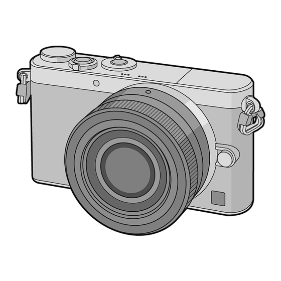
Page 23: Location Of Controls And Components
5 Location of Controls and Components The following description is for DMC-GM1KEB. Some descriptions may differ depending on model suffix. The page number in this chapter does not show the page number of this service manual. 5.1. Camera Body... -
Page 24: Lens
5.2. Lens... -
Page 25: Service Mode
6 Service Mode 6.1. Error Code Memory Function 1. General description This unit is equipped with history of error code memory function, and can be memorized 16 error codes in sequence from the latest. When the error is occurred more than 16, the oldest error is overwritten in sequence. The error code is not memorized when the power supply is shut down forcibly. - Page 26 Error Code List The error code consists of 8 bit data and it shows the following information. Important notice about “Error Code List” About “*” indication: The third digit from the left is different as follows. - In case of 0 (example: 2B001000) When the third digit from the left shows “0”, this error occurred under the condition of INITIAL SETTINGS has been com- pleted.
-
Page 27: Troubleshooting Guide
7 Troubleshooting Guide 7.1. Checking Method of Body and Interchangeable Lens... -
Page 32: About Tilt Sensor Display
7.2. About Tilt Sensor Display The unit has the tilt sensor display function using G (3-axis accelerometer) sensor inside the unit. [Principal of Operation] 1. Movement of “Weight” is detected by capacitance. -------- [A] 2. Each acceleration of the X/Y/Z axis is converted into data and they are output. 3. - Page 33 [Test of the G-Sensor working] • G-Sensor working can be confirmed by G-Sensor data change on the “Edit Memory”. [Operation] (1)-----When you acquire the data of the G-sensor continually, put a checkmark here. (2)-----Raw data of G- sensor is displayed. (3)-----Roll angle (Horizontal Level) and Pitch angle (Tilt) are displayed.
-
Page 34: Wi-Fi Circuit (Main P.c.b.)
7.3. Wi-Fi Circuit (MAIN P.C.B.) 7.3.1. How to Remove Wi-Fi Password Protection To prevent incorrect operation or use of the Wi-Fi function by a third party and to protect saved personal information, this unit pro- tects the Wi-Fi function with a password. It is unable to service with password locked condition. -
Page 35: Service Fixture & Tools
8 Service Fixture & Tools 8.1. Service Fixture and Tools The following Service Fixture and tools are used for checking and servicing this unit. About Adjustment shaft: • VMS7598 for H-FS12032 • VMS7941 for H-H020A... -
Page 36: Clean Box
8.2. Clean Box • The repair quality is considered, and it is recommended working in the environment of specified clean level less than class 10,000 (Federal Standard 209D). [NOTE] • Work in the environment of specified clean level less than class 10,000 (Federal Standard 209D) when inside cleaning of a lens. Please refer to the following service manuals. -
Page 37: Service Position
8.4. Service Position This Service Position is used for checking and replacing parts. Use the following Extension cables for servicing. Table S1 Extension Cable List Parts No. Connection From FP9002 (MAIN) ←→ MAIN-TOP FPC - FP8001 (TOP) RFKZ0487 35pin / 0.3 FFC FP9003 (MAIN) ←→... -
Page 38: Disassembly And Assembly Instructions
9 Disassembly and Assembly Instructions 9.1. Camera Body Part Disassembly Flow Chart 9.1.1. This is a disassembling chart. When assembling, perform this chart conversely. P.C.B. Location 9.1.2. -
Page 39: (S)
Disassembly Procedure 9.1.3. Item Fig. Removal 14 Top P.C.B. (Fig. D23) Screw (N) x 3 Speaker Unit Convex x 1 Microphone Unit Item Fig. Removal Top Earth Plate Rear Case Unit (Fig. D1) Memory Card Audio FPC Fix Plate Battery FP8001 (Flex) Screw (A) x 2 Main-Top FPC... - Page 40 9.1.3.1. Removal of the Rear Case Unit (Fig. D2) 9.1.3.2. Removal of the LCD Unit (Fig. D1) (Fig. D3)
- Page 41 9.1.3.3. Removal of the Main P.C.B. (Fig. D5) (Fig. D4)
- Page 42 (Fig. D7) (Fig. D6)
- Page 43 9.1.3.4. Removal of the Mount and Lens Ring (Fig. D9) (Fig. D8)
- Page 44 9.1.3.5. Removal of the Front Grip Sheet R (Fig. D10) (Fig. D11)
- Page 45 (Fig. D12) 9.1.3.6. Removal of the Front Grip Sheet L (Fig. D13) (Fig. D14)
- Page 46 9.1.3.7. Removal of the Top Case Unit (Fig. D15) (Fig. D16)
- Page 47 9.1.3.8. Removal of the Flash Base Unit 9.1.3.9. Removal of the Flash Unit (Fig. D18) (Fig. D17)
- Page 48 9.1.3.10. Removal of the Strap Holder R 9.1.3.11. Removal of the Battery Unit 1. When removing the strap holder R, rotate 90 degree in the direction of arrow (1) strongly. (counterclockwise) If it can not rotate, remove the glue near the rear side. (Use the tweezers and remove a small quantity.) 2.
- Page 49 9.1.3.13. Removal of the Battery Case Plate 9.1.3.14. Removal of the Top P.C.B., and Battery Out Spring Speaker Unit and Microphone Unit (Fig. D22) (Fig. D23)
-
Page 50: Disassembly And Assembly Procedure For The Lens
9.2. Disassembly Assembly Procedure for the Lens Please refer to the following service manuals about Disassem- bly and Assembly of bundled lenses. • H-FS12032PP/E/GK : Order No.DSC1311036CE • H-H020APP/E/GK : Order No.DSC1307028CE (Fig. D24) NOTE: (When Installing) Make sure to confirm the following points when installing: •... -
Page 51: Measurements And Adjustments
10 Measurements and Adjustments 10.1. Matrix Chart for Replaced Part and Necessary Adjustment The relation between Replaced part and Necessary Adjustment is shown in the following table. When concerned part is replaced, be sure to achieve the necessary adjustment(s). As for Adjustment condition/procedure, consult the “Adjustment method” which is available in Adjustment software. NOTE: After adjustments have been terminated, make sure to achieve “INITIAL SETTINGS”. - Page 52 *6 NOTE: (About the electronic 1st curtain shutter adjustment) • This model adopted electronic 1st curtain shutter and mechanical 2nd curtain shutter for miniaturization. • Use a collimator for shutter adjustment (RFKZ0630) to make parallel light. • Refer to the adjustment method in the adjustment software for details. *7 NOTE: ( AVCHD function inspection) •...
-
Page 53: Maintenance
11 Maintenance 11.1. Notice in external cleaning 11.1.1. ABOUT THE BODY NOTE: Before cleaning the camera, remove the battery and/or disconnect power plug from the outlet. Also, remove the memory card and lens unit. 11.1.1.1. DUST/DIRT ON THE OUTER CASING PART (S) 1. -
Page 54: Block Diagram
12 Block Diagram 12.1. Overall Block Diagram FRONT-MOUNT UNIT MOS IMAGE SENSOR MEMORY LENS UNIT 4/3” 16MEGA PIX CARD (Built in AFE) ECM(L) IC3901, STEREO IC3921 MICROPHONE (27MHz) IC9102 SHUTTER ECM(R) REGULATOR SSWF LENS CONNECTOR SYSTEM IC UNIT MICROPHONE SPEAKER AMP SPEAKER VIDEO OUT IC9901... -
Page 55: System Control Block Diagram
12.2. System Control Block Diagram IC9102 TOP P.C.B. (SYSTEM IC) CL9002 AF LED P.C.B. (POWER ON L) (POWER ON L) FP9002 FP8001 POWER SW POWERSWONL S8001 AF ASSIST LED (LED PWR OUT) (LED PWR OUT) FP9002 FP8001 LEDOUT0 (Green) POWER LED D7501 D8002 RL8001... -
Page 56: Video/Audio Process(1) Block Diagram
12.3. Video/Audio Process(1) Block Diagram IC6003 (NOR FLASH ROM/256M-bit) DATA CTL SIG ADDRESS FRONT-MOUNT UNIT LCD UNIT (SENSOR) FP9006 SENSOR P.C.B. IC6001 LCDOUT0-15 (VENUS ENGINE) T3 T2 T1 FP9006 (SDODA0P) FP3002 FP3901 AF16 IS SAB0 P (LCDVD) FP9006 FP3002 FP3901 (SDODA0M) AE16 IS SAB0 M... -
Page 57: Video/Audio Process(2) Block Diagram
12.4. Video/Audio Process(2) Block Diagram IC6001 (Wi-Fi) (VENUS ENGINE) (G WiFi CLK) (G-WiFi-CLK) SDIO CLK GPIO3 Wi-Fi (WiFi CMD) (WiFi CMD) ANTENNA GPIO4 SDIO CMD (WiFi DAT3) (WiFi DAT3) GPIO8 SDIO D3 (WiFi DAT0) (WiFi DAT0) GPIO5 SDIO D0 FP8501 (WiFi DAT1) (WiFi DAT1) 2.4G ANT... -
Page 58: Lens Flash Block Diagram
12.5. Lens Flash Block Diagram IC6001 (VENUS ENGINE) FRONT-MOUNT UNIT (LENS CONNECTOR) FP9001 PW LEN4.2V LEN4R2V 13-16 (LSDET) FP9001 AD1 IN1 LSDET (LSRST) FP9001 GPIO42 LSRST (LSB2L) FP9001 GPIO19 LSB2L (LSL2B) FP9001 LSL2B GPIO17 (LSDIO) FP9001 GPIO20 LSDIO (LSCK) FP9001 GPIO18 LSCK (LSB2A) -
Page 59: Power Block Diagram
12.6. Power Block Diagram TOP P.C.B. CL1101 CL1001 P8001 F8001 PW D1.1V (PW UNREG) FP8001 FP9002 BAT+ 10-17 9-16 (BAT THERMO) FP8001 FP9002 BAT THERMO 2 BATTERY CATCHER BAT DET(NC) F1002 CL1201 CC8002 FP8001 FP9002 BAT- PW D3.0V IC1001 (8CH SW REGULATOR) POWER SW CL9002 S8001... -
Page 60: Wiring Connection Diagram
13 Wiring Connection Diagram 13.1. Interconnection Diagram BATTERY AF LED P.C.B. STEREO AUDIO FPC MICROPHONE SPEAKER RL8002 RL8001 TOP P.C.B. (FOIL SIDE) MAIN-TOP FPC FLASH UNIT LENS UNIT FP9002 UNREG GND UNREG GND UNREG GND UNREG GND UNREG GND UNREG GND BAT THERMO FP8501 UNREG...
Need help?
Do you have a question about the LUMIX DMC-GM1KP and is the answer not in the manual?
Questions and answers