Table of Contents
Advertisement
Quick Links
Advertisement
Table of Contents

Related Manuals for PCB LARSON DAVIS SoundAdvisor NMS045


Summary of Contents for PCB LARSON DAVIS SoundAdvisor NMS045
- Page 1 SoundAdvisor™ Model NMS045 Permanent Noise Monitoring System Reference Manual...
- Page 2 Larson Davis SoundAdvisor Model NMS045 Permanent Noise Monitoring System Reference Manual...
- Page 3 Copyright Copyright 2023-2024 PCB Piezotronics, Inc. This manual is copyrighted, with all rights reserved. The manual may not be copied in whole or in part for any use without prior written consent of PCB Piezotronics, Inc. Trademarks in this Manual Android and the Google Play Store are trademarks of Google, LLC in the U.S.
-
Page 4: Preparing The Battery
Module 1 System Overview - - - - - - - - - - - - - - - - - - - - - - - - - - - - - - - - - - - - - - - - - - - - - - - - - 1 1.1 System Contents 1.2 Optional Accessories 1.3 Wiring Diagram... - Page 5 Chapter 1 System Overview The SoundAdvisor Model NMS045 Permanent Noise Monitoring System includes coordinating instruments permanently mounted on a vertical, steel pole, which work together with the 831C sound level meter to provide long-term, outdoor, sound level monitoring. In this module: System Contents .........................1-2 Optional Accessories ......................1-6 Wiring Diagram ........................1-7...
- Page 6 1.1 System Contents In this section, review your system contents to identify items received. NMS Systems: Outdoor Equipment for Environmental Noise Monitoring Your permanent outdoor noise monitoring system may include any of the following kits. Figure 1-2 and Table 1.3 describe each kit. Images of NMS045 System Contents Figure 1-2 Table 1.3 Description of SoundAdvisor 831C Permanent NMS Kits (831C-045)
- Page 7 Table 1.3 (Continued)Description of SoundAdvisor 831C Permanent NMS Kits (831C-045) Kits to Order ----> Contents Cables & Adapters: SLM cables Ethernet + USB Hub (DVX013) USB power cable for USB Hub (CBL235) Solar cables: Solar Charger (CBL226-03) Solar panel cable (CBL223-12) Outdoor Mic Adapter (ADP100) Mounting pipe (426A12-NPT) Tilt-down pole (TRP019)
- Page 8 Table 1.6 Description of Mountable Equipment Case Kits (EPS045) Figure 1-7 Kits to Order ----> Contents Weather resistant, mountable case Surge suppressor Durable mounting hardware (OPT1) Adapter for EPS kits (1.5 to 0.75 pipe adapter) Table 1.8 Description of Weather Sensor Kits Figure 1-9 Kits to Order ---->...
- Page 9 Table 1.12 Optional Accessories Items to Order ----> Contents Charger for SLA battery(PSA040) Charger for LiFePo battery (PSA043) Solar panel & support bracket (SLP003) Weather sensor mount (TRP012) AC power supply (PSA041) Security band for equipment box (EPS043-BAND) NMS045 Reference Manual System Contents...
- Page 10 1.2 Optional Accessories Hardware • 32 GB USB Flash Storage (831-MEM32G) • Precision Acoustic Calibrator (CAL200) Firmware Sound Recording Firmware (831C-SR) The optional Sound Recording firmware upgrade enables you to make event-based and manual sound recordings in WAV or OGG format. Recordings are stored in the measurement data and can be shared via email.
- Page 11 1.3 Wiring Diagram The following diagram shows the system with all available options, including both solar and AC power options. At least one battery is needed to run the system. Figure 1-13 System Wiring Diagram Weather/Wind Sensor PRM2103-FF Microphone and Preamplifier Cellular Antennas CBL222-20...
- Page 12 Figure 1-14 is color -coded to show each option with components. • Blue - COM-RV50X-045NA/EU:APAC Cellular Gateway • Purple - SEN031-045, SEN032-045 Weather/Wind System • Green - Solar Powered System • Orange - AC Powered System • Pink - Batteries, one or two •...
- Page 13 1.4 Understanding NMS045 Power Consumption The NMS045 system draws DC power from a connected battery when not powered via solar panel, wall outlet, etc. Estimating Power Consumption To estimate how much power your system requires per 24 hours, use the formula shown in Figure 1-15.
- Page 14 Battery Capacity (BAT021, LiFePo battery = 540 Wh; (BAT 019, SLA battery = • 420 Wh) Discharge cutoff limit is 10% • Consumption per day = 80 Wh (typical) • • Enter the Slope of the solar panel, and the Azimuth. To find the azimuth, do the following: Open this link for the NOAA ESRL Solar Position Calculator.
-
Page 15: Table Of Contents
Getting Started Chapter 2 Before installing the components of the NMS045 system, you will need to complete several “first use” procedures such as making cable connections, and configuring remote communication and the sound level meter as described in this module. In this module: Preparing the Battery ......................2-11 Assembling the Solar Bracket ...................2-12... -
Page 16: Assembling The Solar Bracket
Figure 2-1 Battery with Cables Step 2. Charge the battery prior to installation by using the battery charger recommended for your battery type. CAUTION If you are using two 12 V batteries, ensure both batteries are fully charged before installation. You risk blowing a fuse if one is depleted and one is charged. -
Page 17: Assembling Main Plate And Components
"Making the Most of Your LEARN MORE To calculate solar tilt, etc., see Sunlight Hours" on page 2.3 Assembling Main Plate and Components Your NMS045 system arrives partially assembled. This section describes the final assembly procedure. Step 1. Mount the separate components of the system as shown in Figure 2-3. Figure 2-3 831C-045 Assembly Attach the gateway through the holes in the main plate by using the 2 included screws and lock nuts. -
Page 18: Establishing Service For The Gateway
2.4 Establishing Service for the Gateway Establishing cell service for the gateway includes purchasing a SIM card with cellular service and installing it. As indicated in this section, you can also opt to have Larson Davis install and activate the SIM when your system is prepared at the factory. 2.4.1 Purchasing Cellular Service Review this section prior to purchasing cell service. -
Page 19: Installing The Sim Card
Recommended next step: If Larson Davis is configuring your system, move to 2.5.1 "Configuring • Intrusion Detection" on page 19. Otherwise, move to 2.4.2 "Installing the SIM Card" on page 15. 2.4.2 Installing the SIM Card With the system powered off, install the SIM card as shown here. Step 1. - Page 20 • SSH and DMZ Host are disabled, which increases system security by block- ing potential sources of unauthorized access • The gateway routes HTTPS communications through the secure HTTP socket to prevent unauthorized “listening” • The gateway uses a unique port for local, and for remote access, to dis- courage unauthorized access Additional Services •...
- Page 21 Step 4. Open a web browser on the connected PC, and navigate to http:// 192.168.14.31:9191. This is the ACEmanager configuration console. Step 5. Log in to ACEmanager as “user” with the password “LD_NMSystem16”. TAKE NOTE If the login doesn’t work, verify that the LD settings are loaded as 2.8 "Configuring the Gateway for Larson Davis Instruments"...
- Page 22 Part 2: Editing Settings for Remote Communication Step 1. Navigate to WAN/Cellular SIM Slot 1 Configuration and expand the Network Credentials menu by pressing the + icon. Figure 2-9 WAN/Cellular Step 2. Enter the APN provided by your cellular provider in the User Entered APN. Step 3.
-
Page 23: Configuring Intrusion Detection
power consumption resulting from unauthorized users repeatedly attempting to connect. Setting Up the Trusted IP List Click on the Security tab, choose Trusted IP - Inbound (Friends) from the left pane. Under Inbound Trusted IP List (Inbound Trusted IP Range) enter the public IP address given to you by your cellular provider, and any other IP address (or address ranges) that should have remote access to the gateway. - Page 24 Step 2. Click the Events Reporting tab, and choose theIntrusion Detection section. Figure 2-12 Intrusion Detection Settings If there is no Intrusion Detection setting available, this may TAKE NOTE indicate that the gateway has not been prepared for use with Larson Davis 2.8 Configuring the Gateway for Larson instruments.
-
Page 25: Verifying Remote Communications Via A Mobile Device
Step 7. Complete all fields in the General menu, click Apply, then click Reboot. Step 8. In your email client, review and configure any additional security settings. For more information, consult your email provider’s documentation, or your IT professional. Example Only: For the Gmail account shown in this section, the following security settings are required after logging in to Gmail: Go to My Account ... -
Page 26: Configuring Slm Settings On The 831C
Step 6. Tap the blue plus button to connect. The Meters Add Meter screen closes. If the NMS system and your mobile device have cellular service, the serial number of the 831C displays in the Meters list with a blue meter icon. The meter is connected on your device. -
Page 27: Configuring Basic Slm Settings
On a PC, explore the included Larson Davis USB drive. Locate and install “LDSetup.exe” in the G4 LD Utility Software folder. The program creates a PCB Piezotronics folder on the Start menu and a shortcut to G4 on the Desktop. -
Page 28: Verifying Remote Communications Via A Mobile Device
2.6.3 Verifying Remote Communications via a Mobile Device Establishing a connection to the SoundAdvisor™ 831C SLM via WAN or LAN prior to deployment verifies that the service is working properly. This section show how to establish a remote connection using a mobile device. You can also establish this same connection to the 831C SLM using G4 LD Utility on your PC. -
Page 29: Using Soundlink
2.7 Using SoundLink SoundLink is an IP hosting service that provides secure communication with your remote noise monitoring systems using a dynamic IP address. This service from Larson Davis simplifies remote communication with your NMS system. It is an alternative to using a public, static IP address from your cellular provider, or a viable solution if one is not available. -
Page 30: Logging In To Acemanager
2.8.1 Logging In to ACEmanager Step 1. Attach the USB to mini-B cable from the PC to the gateway. Step 2. Open a web browser. Step 3. Enter http://192.168.14.31:9191 in the address field. Step 4. Login as “user” with default password “12345”. Figure 2-15 Sierra Wireless ACEmanager Login Page Step 5. -
Page 31: Configuring Ld Settings Using The Template File
Enter a unique password in New Password, and again in Retype Password. Record your password. If you forget it you will need to reset the RV50X to factory settings and reconfigure. Click Change Password, then click Apply. 2.8.2 Configuring LD Settings Using the Template File Using the LD Settings Template File is the quickest and easiest way to configure the gateway. -
Page 32: Configuring Ld Settings Without The Template File
2.8.3 Configuring LD Settings Without the Template File If you would prefer to manually configure the RV50X instead of uploading the template file, complete this section. Step 1. Log in to ACEmanager as shown in 2.8.1 Logging In to ACEmanager. Step 2. - Page 33 Step 5. Navigate to the Services tab, and in the left pane, select the ACEmanager section. Step 6. Edit the values to match what is shown in Figure 2-20 and click Apply. Figure 2-20 Services - ACEmanager HTTPS Only Step 7. In the left pane, click the Power Management section, and expand the Power Saving Modes menu.
- Page 34 Step 9. In the left pane, select Telnet/SSH, then set Telnet/SSH Echo to Disable and click Apply. Figure 2-22 Telnet/SSH Step 10. Select the Location tab, then select Global Settings in the left pane. Step 11. From the Location Service drop-down, choose Enable. Step 12.
- Page 35 Step 13. In the left pane, select Local/Streaming, modify the values to match Figure 2- 24, and click Apply. Figure 2-24 Local/Streaming Configuration Values Step 14. Navigate to the Events Reporting tab. Step 15. Change the Action Name to be Intrusion Detection, and the Action Type to be Email.
- Page 36 Step 17. Navigate to the Serial tab, select Disable from the Serial Port drop-down menu, and click Apply. Figure 2-26 Serial Port Settings Step 18. Navigate to the LAN tab, and select the USB section in the left pane. Step 19. Verify that the settings are as shown in Figure 2-27, and click Apply.
- Page 37 Step 21. Verify that the settings are as shown in Figure 2-28, and click Apply. Figure 2-28 I/O After this change you will not be able to connect to the gateway TAKE NOTE with a wired Ethernet connection. If you need to restore the wired connection without connecting to the gateway through the cellular connection, do a hard reset on the gateway.
- Page 38 Chapter 3 Installing the NMS System Before installing the NMS system components, you will need to arrange for the pole and box to be installed by a professional contractor. If needed, Larson Davis can provide your contractor with mechanical drawings detailing our recommendations. Contact information is found on the back cover of this manual.
- Page 39 3.2.1 Mounting the Fiberglass Enclosure Before you begin: • Ensure you have tools ready for mounting the enclosure • Recommend to not install alone • Choose the appropriate mounting instructions for your system from the following sections: 3.2.1.1 Mounting the Enclosure with an AC System 3.2.1.2 Mounting the Enclosure with a Solar Option 3.2.1.3 Mounting the Fiberglass Enclosure OPT1 (non standard pole) NMS045 Reference Manual...
- Page 40 3.2.1.1 Mounting the Enclosure with an AC System Step 1. Place the bushings into the support plate Step 2. Push bushings through enclosure wall and add sealing washers between enclosure wall and pole Step 3. Attach bushings to pole and tighten down to secure enclosure to the pole Step 4.
- Page 41 Step 5. Use the 4 10/32 screws to attach the backplate to the enclosure Figure 3-2 NMS045 AC Enclosure Installation NMS045 Reference Manual Installing the NMS045 on the Pole...
- Page 42 3.2.1.2 Mounting the Enclosure with a Solar Option Before you begin: Step 1. Place the bushings into the Support plate Step 2. Push bushings through enclosure wall and add sealing washers between enclosure wall and pole Step 3. Attach bushings to pole and tighten down to secure enclosure to the pole Step 4.
- Page 43 3.2.1.3 Mounting the Fiberglass Enclosure OPT1 (non standard pole) TAKE NOTE This option can be used to mount the enclosure to objects other than the Larson Davis TRP019, i.e. Power pole, wall, etc. TAKE NOTE Avoid putting holes in the top or bottom of the box. Any holes toward the bottom of the case need to be above the battery height in the side.
- Page 44 Step 2. (Optional) For electrical connection porting, we recommend adding a hole to the case on the side opposite the door hinges, approximately 10” from the bottom, centered on the case. Any port hole must be sealed using a gland or sealant.
- Page 45 Slide the bottom rail into position and lightly tighten the bolts using the 3/8” Hex wrench. Figure 3-8 OPT1 Box Preparation Step 4. Level and mount the top rail to the wooden pole or wall using the lag bolts and the fender washers from the inside of the channel.
- Page 46 Step 5. Slide the box with bottom rail onto the top mounted rail. Mark the location of the bottom rail. Remove the box assembly from the top rail, and remove the rail from the bottom of the box leaving the channel nut and screw loosely attached. Figure 3-10 OPT1 Marking Bottom Rail Location Step 6.
- Page 47 3.2.2 Positioning the Pole Tip Down Step 1. Attach the 2 carabiners to either side of the rope. The length of the rope between the 2 carabiners should be 11 feet (3.3 meters). Cut or tie the rope to modify the length. Step 2.
- Page 48 Figure 3-14 Pole in tip-down position 3.2.3 Installing the Battery and Main Plate Before you begin: • If the system includes a solar panel or weather station, do not install the battery until you’ve mounted each of these components. See Chapter 4 Installing Optional Components for installation procedures.
- Page 49 Step 2. Place the main plate on the outside of the box, on the battery plate shoulder screws as shown in Figure 3-16. Figure 3-16 831C-045 on Shoulder Screws. Battery plate shoulder screws are designed to hold the main plate as you work on it.
- Page 50 Step 1. Open the back of the pole as shown in Figure 3-18. Figure 3-18 Back side of Pole Step 2. Feed the CBL222-20 (and solar, weather, or other cables) through the top hole in the back of the pole at point A until you see it exit the pole at point B. (Refer to Figure 3-19.) Figure 3-19 Cable Routing in TRP019 Pole CBL233-12 Solar Outlet (red)
- Page 51 Step 3. To feed the cable down the second half of the pole, we recommend using fish tape. See Figure 3-20. If the end of the cable gets stuck at the weather cable outlet, recoil TAKE NOTE and try again until it clears the opening. Figure 3-20 CBL222-20 Routing with Fish Tape Attach fish tape to CBL222-20.
- Page 52 Step 5. Follow the steps shown in Figure 3-22 to thread the mic through the EPS2116 mic protection. If desired, you can calibrate the mic first, then install mic protection. Figure 3-22 EPS2116 Threading Thread the CBL222-20 cable up through the base and top of the EPS2116.
- Page 53 3.2.6 Installing Components In the Box Step 1. From the front of the box, connect the CBL222-20 to the top of the 831C. Figure 3-23 CBL222-20 Connection Step 2. Lift the mounting plate off the shoulder screws, then mount the back plate on the shoulder screws.
- Page 54 Figure 3-25 For AC Power: PSA040 to Surge Suppressor PSA040 (AC only) to surge protector After connection, tie the cord out of the way with provided zip tie as shown. Step 4. Connect the battery to the power block on the line called Power Block. Figure 3-26 Suggested Setup for Control Power Block Weather 831C SLM...
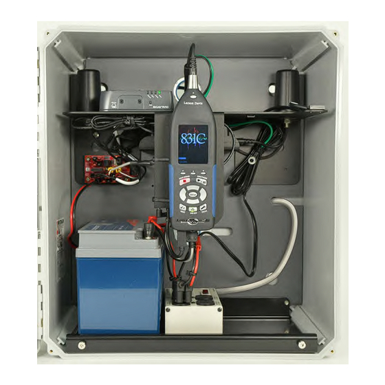
- Page 55 Figure 3-27 Components Installed Step 5. When the battery is connected, the system powers on. The 831C power button controls the power in the whole system. It is used to turn off and on the NMS045. 3.3 Performing a Field Operational Check Follow these steps prior to leaving the installed system.
- Page 56 Solar Charging The battery is fully charged when the PSA038 Solar Charger is green. A blinking LED indicates charging. See A.2.3 "LED Indicators for Solar Charge Controllers" on page 5. Step 2. Connect to the 831C using the LD Atlas app on a mobile device to verify cellular service functioning.
- Page 57 Step 2. If the windscreen is on the microphone, remove it by holding the windscreen and birdspike together, and unscrewing the assemblies until they come apart. Step 3. Gently place the calibrator over the microphone. Apply it carefully to avoid sudden large pressure changes to the microphone diaphragm.
- Page 58 Step 8. After a few seconds, a message appears indicating the measured difference and a prompt to save the results. Click Yes to save the calibration or No to reject it. Figure 3-30 Calibration Results Step 9. Gently remove calibrator from microphone. Click Calibration History to view either acoustic calibration or calibration TRY THIS check summaries.
- Page 59 Installing Optional Components Chapter 4 The following components can be installed in conjunction with the field installation described in Module 3. IN THIS MODULE: Required Tools (not supplied) ..................4-55 Solar Installation to TRP019 .....................4-55 Solar Installation to Wall or Wood Pole ................4-61 Weather Installation ......................4-67 4.1 Required Tools (not supplied) The tools listed are a recommended to have available for installation.
- Page 60 Step 2 Locate solar outlet hole in TRP019. See Step 1. Open the back of the pole as shown in Figure 3-18. Step 3 Install the bracket and mount it to the solar panel following the manufacturer’s instructions included with the SLP003 solar panel and mount.
- Page 61 FIGURE 4-1 Solar Panel Install NMS045 Reference Manual Solar Installation to TRP019...
- Page 62 Step 6 The solar cable CBL233-12 connecst the panel with the charge controller. Feed the cable down the pole, out the bend, then out the bottom hole and into the box. FIGURE 4-2 Feed Cable Down Pole Step 7 To get the solar cable through the gland bend the connectors so they are in-line, one pointing up and one pointing down.
- Page 63 To disconnect the solar connectors, use the included ring tool. TAKE NOTE Step 8 Connect cables, ensuring they are completely seated. You will hear a small snap when they are connected. FIGURE 4-4 Connect Solar Cable to Panel Step 9 Feed CBL233-12 into the box through the bottom hole. Connect to solar charger on the area marked Panel.
- Page 64 screwdriver, insert the correct cable ends, then tighten down. Black to negative, red to positive. FIGURE 4-5 CBL233-12 to Solar Charger Black to negative Red to positive Step 10 Connect CBL226-03 to the solar charger in the space marked Battery. Loosen the screws, insert the correct cable ends, then tighten down.
- Page 65 Power Block. After everything else is connected to the control power block, connect the battery to the line marked Power Block. Step 12 Check that the panel is charging the battery, see “LED Indicators for Solar Charge Controllers” on page A-5. FIGURE 4-7 Solar Panel on Tip-Down Pole 4.3 Solar Installation to Wall or Wood Pole...
- Page 66 Step 2 Fasten 2 L-Channels to each L-Bracket as shown in Figure 4-8 Fasten L- Channels to L-Bracketsl FIGURE 4-8 Fasten L-Channels to L-Bracketsl Step 3 Fasten top L-Channel to wall or pole using 2 hex head screws. The screws needed are not provided. Recommended to use 3/8” hex head screws appropriate for wall or pole material type with 3/8”...
- Page 67 FIGURE 4-9 Mounting Support Arms and T-Slotted Brackets Step 6 Mount bottom L-Bracket to the wall or wooden pole. using 2 hex head screws. The screws needed are not provided. Recommended to use 3/8” hex head screws appropriate for wall or pole material type with 3/8” fender washers.
- Page 68 Step 7 Mount the solar panel to the bracket following the manufacturer’s instructions included with the SLP003 solar panel and mount. See 2.2 "Assembling the Solar Bracket" on page 12. FIGURE 4-10 Mounting Solar Panel to Bracket Step 8 Connect cables, ensuring they are completely seated. You will hear a small snap when they are connected.
- Page 69 FIGURE 4-11 Connect Solar Cable to Panel Step 9 Feed CBL233-12 into the box through the bottom hole. Connect to solar charger on the area marked Panel. Loosen the screws with a flat head screwdriver, insert the correct cable ends, then tighten down. Black to negative, red to positive.
- Page 70 Step 10 Connect CBL226-03 to the solar charger in the space marked Battery. Loosen the screws, insert the correct cable ends, then tighten down. Black to negative, red to positive. FIGURE 4-13 CBL226-03 to Solar Charger Red to positive Black to negative Step 11 After the plate has been placed into the box (see "Step 2."...
- Page 71 4.4 Weather Installation Step 1 The pole should be in the tip down position. See 3.2.1 "Mounting the Fiberglass Enclosure" on page 35. Step 2 Using fish tape, feed CBL229-20 out the top hole in the box, up the pole and out at the bend.
- Page 72 FIGURE 4-15 Feed CBL229-20 Through Weather Arm Step 5 Bolt the weather arm to the pole with the gasket in place using a 9/16- inch wrench. FIGURE 4-16 Weather Arm Bolted to the Pole NMS045 Reference Manual Weather Installation...
- Page 73 Step 6 Connect the weather or wind sensor to the cable, push the slack back through the arm, and connect the sensor to the arm. FIGURE 4-17 Feed CBL229-20 Through Weather Arm Step 7 Adjust the sensor, so that north on the sensor aligns with north on a compass once the pole is brought back into place.
- Page 74 Appendix A Additional System Information IN THIS MODULE: NMS045 Power Information - - - - - - - - - - - - - - - - - - - - - - - - - - - - - - - - - - - - - - - - - - - - - - - A-1 A.1.1 Power Draw A-1 A.1.2...
- Page 75 Table A.1 Typical Runtime One 45 Ah LiFePo One 35 Ah SLA Configuration Battery Battery (BAT019-045) (BAT020-045) NMS045 with cellular gateway 6 days* 4 days* These are average numbers and should be used only as reference. For example, as batteries age or operate at low temperatures the runtime may be reduced. A.1.2 Sunlight Hours You are encouraged to take advantage of the most daylight, direct sun for your area.
- Page 76 System Power Indicators The system power status is indicated by the green LED behind the SLM power button Table A.2 Power Status LED Indicator Status Green LED System is powering up or FAST, SHORT GREEN BLINK shutting down Measurement Status Indicators SLM measurement status is indicated by the LEDs behind the Stop button and the Play/Pause button...
- Page 77 A.2.2 LED Indicators for RV50X Cellular Gateway When installed and running, the state of the gateway is indicated by the 4 LEDs on the side and bottom of the device. Individual lighted LEDs and combination lighted LED indications are listed in Table A.4: Table A.4 Gateway LED Indications Color/Pattern...
- Page 78 A.2.3 LED Indicators for Solar Charge Controllers The NMS044 solar charge controller has 1 multi-color LED which indicates unit status as shown in this section. The Genasun Lead Acid solar charge controller (Figure A-1) is one example; your model may differ slightly. Figure A-1 Example: Genasun Solar Charge Controller LEARN MORE...
- Page 79 Table A.4 (Cont) Genasun Solar Charge ...LED ERROR INDICATIONS Controller LED Indication Patterns ...LED STATUS INDICATIONS Panel Voltage Too High Only 12V nominal solar panels may be used with this controller. Battery Charged The battery is in the SETS OF 6 RED BLINKS absorption or float charging stage.
- Page 80 A.4 Configuring the Gateway for Larson Davis Instruments Complete this section ONLY if you purchased a new RV50X cellular gateway CAUTION from someone other than Larson Davis, or if it has been reset to factory default settings. Larson Davis modifies the Sierra Wireless RV50X gateway configuration to conserve power, increase security, and provide additional services.
- Page 81 Figure A-2 Sierra Wireless Login Step 5. Take note of the device’s firmware version. If needed, update to the latest version. Updating Firmware to the Latest Version (Recommended) Go to http://source.sierrawireless.com/. Select the name of your device, then select Firmware Package. If needed, download and update the firmware according to the manufacturer's instructions.
- Page 82 A.4.2 Configuring LD Settings Utilizing the Template File Utilizing the LD settings template file is the fastest and simplest method of configuring the gateway. Step 1. Select Template in the top right. This opens the Template upload window. Figure A-4 Step 2.
- Page 83 Figure A-5 Edit the Ping Response Step 3. Go to the Security tab, and select the Port Forwarding section in the left pane. Step 4. Edit the values in the Port Forwarding section to match what is shown in Figure A-6, and click Apply.
- Page 84 In the left pane, click the Power Management section, and expand the Power Saving Modes menu. From the Processor Power Saving Mode drop-down, select Enable and click Apply. Figure A-8 Services - Power Management Step 7. To promote gateway security, complete the following process. In the left pane, select Telnet/SSH, then set Telnet/SSH Echo to Disable and click Apply.
- Page 85 Set the TCP Location Port to 9494, and click Apply. Figure A-10 Location Settings Step 8. In the left pane, select Local/Streaming, modify the values to match Figure A- 11, and click Apply. Figure A-11 Local/Streaming Configuration Values Step 9. Navigate to the Serial tab, select Disable from the Serial Port drop-down menu, and click Apply.
- Page 86 Figure A-12 Serial Port Settings Step 10. Navigate to the LAN tab, and select the USB section in the left pane. Step 11. Verify that the settings are as shown in Figure A-13, and click Apply. Figure A-13 USB Port Settings Step 12.
- Page 87 Figure A-14 Settings on the I/O Tab Step 14. Navigate to the LAN tab, and select the Ethernet section in the left pane. After this change you will not be able to connect to the gateway with a wired TAKE NOTE Ethernet connection.
- Page 88 Appendix B Technical Specifications IN THIS MODULE: Physical Characteristics ..................... B-1 Main Plate Dimensions EPS045 Case Dimensions Steel Pole (TRP019) Dimensions B.1 Physical Characteristics OPERATING TEMPERATURE • -40 °C to 50 °C ambient temperature Weights are approximate and for reference only. TAKE NOTE WEIGHT •...
- Page 89 FIGURE B-1 Main Plate Dimensions NMS045 Reference Manual Physical Characteristics...
- Page 90 FIGURE B-2 EPS045 Case Dimensions 2.380 12.27 2.380 13.50 .531 2.125 18.12 10.34 8.72 2.500 10.000 19.69 NMS045 Reference Manual Physical Characteristics...
- Page 91 FIGURE B-3 Steel Pole (TRP019) Dimensions NMS045 Reference Manual Physical Characteristics...
- Page 92 Larson Davis - a PCB Piezotronics division LarsonDavis.com P/N INMS045.01 NMS045 Reference Manual, Revision D ©2024 PCB Piezotronics, Inc. Worldwide Corporate Headquarters Toll-free (in the US): 888-258-3222 3425 Walden Avenue Phone: 716-926-8243 Depew, NY 14043-2495 USA USA fax: 716-926-8215 E-mail: sales@larsondavis.com...
Need help?
Do you have a question about the LARSON DAVIS SoundAdvisor NMS045 and is the answer not in the manual?
Questions and answers