
Related Manuals for DS18 RZR-GBSUB10LD


Summary of Contents for DS18 RZR-GBSUB10LD
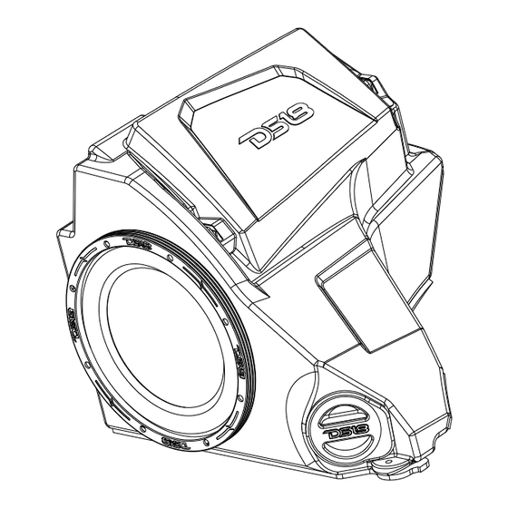
- Page 1 OWNER’S MANUAL RZR- GBSUB10LD MANUAL DEL USUARIO 10" LOADED SUBWOOFER ENCLOSURE FOR POLARIS RZR GLOVE-BOX CAJA PARA SUBWOOFER DE 10" INCLUIDO PARA LA GUANTERA DEL POLARIS RZR SPECIALLY DESIGNED FOR POLARIS ENGLISH | ESPAÑOL...
-
Page 2: Installation
RZR- GBSUB10LD 10" LOADED SUBWOOFER ENCLOSURE FOR POLARIS RZR GLOVE-BOX CAJA PARA SUBWOOFER DE 10" INCLUIDO PARA LA GUANTERA DEL POLARIS RZR FEATURES: CARACTERÍSTICAS: • CAJA DE POLIETILENO (PE) DURALE • DURALE POLYETHYLENE (PE) BOX • CABLE DE ALTAVOZ DE ENTRADA DE •... - Page 3 RZR- GBSUB10LD INSTALLATION / INSTALACIÓN: 6. Remove one (1) T40 Torx screw located directly above left foot rest on passenger side. 6. Retire un (1) tornillo Torx T40 ubicado directamente encima del reposapiés izquierdo en el lado del pasajero. 7. Install the large hardware bracket on the subwoofer enclosure using one bolt as pictured.
-
Page 4: General Specifications
RZR- GBSUB10LD GENERAL SPECIFICATIONS / ESPECIFICACIONES GENERAL: Nominal Diameter / ...................10" / 254mm Diámetro Nominal Nominal Impedance / ....................2 Ohms Impedancia Nominal RMS Power Handling / ..................600W Manejo de Potencia RMS MAX Power Handling / ..................1200W Manejo de Potencia MAX Sensitivity (1w/1m) / .................... - Page 5 INSTALLATION / INSTALACIÓN: 2. Extract the (4) T40 screws surrounding the 2. Extraiga los (4) tornillos T40 que rodean el sistema de ride command system and (2) push pins found in comando de suspensión y los (2) pasadores que se the dash pocket.
- Page 6 INSTALLATION / INSTALACIÓN: 10. Install the remaining screws and hand tighten. 10. Instale los tornillos restantes y apriételos a mano. 11.Install the supplied screw in the lower mounting hole aligning with the factory hole in the footwell and tighten the screws from steps 6 ,7 and 10.
-
Page 7: Warranty
17.84” / 453.17mm 17.28” / 439.03mm WARRANTY GARANTÍA Please visit our website DS18.com for more information Visita nuestra página web DS18.com para obtener más on our warranty policy. información sobre nuestra garantía. We reserve the right to change products and specifications Nos reservamos el derecho de cambiar productos y at any time without notice. - Page 8 FOR MORE INFORMATION PLEASE VISIT DS18.COM...
Need help?
Do you have a question about the RZR-GBSUB10LD and is the answer not in the manual?
Questions and answers