Table of Contents
Advertisement
Quick Links
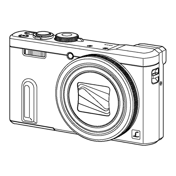
DMC-TZ60EB
Model No.
DMC-TZ60EE
DMC-TZ60EF
DMC-TZ60EG
DMC-TZ60EP
DMC-TZ60GA
DMC-TZ60GN
DMC-TZ61EG
DMC-ZS40P
DMC-ZS40PC
DMC-ZS40PU
DMC-ZS40GK
DMC-ZS40GH
DMC-ZS40GT
Colours
(S)....................Silver Type
(K)....................Black Type
© Panasonic Corporation 2014.
Unauthorized copying and distribution is a violation
of law.
ORDER NO.DSC1403001CE
B26
Digital Camera
Advertisement
Table of Contents


Need help?
Do you have a question about the LUMIX DMC-TZ60EB and is the answer not in the manual?
Questions and answers