Advertisement
Quick Links
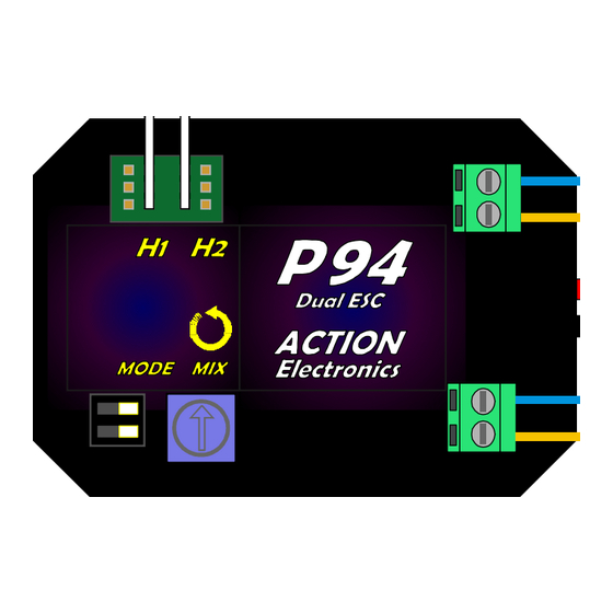
P94L
Type: Dual ESC and Mixer Module. Equivalent to two fully operational ESCs and a mixer, all in the same
case. Will suit most types of DC
No of channels required:
Motor voltage:
Maximum continuous current rating:
Modes: 4 different modes of operation, selectable by user via on-board 2-way DIL switches:
Mode 1: Dual electronic speed controllers - Each ESC works from a separate channel i.e. "Tank Steering";
Mode 2: Dual thruster mode - Controls bow and stern thrusters. Skipper selects either Traverse (where
thrusters work in the same direction and slew the model sideways) or Spin (where the
thrusters work in opposite directions and spin the model on its own axis). Selection is done by
"blipping" the rudder stick hard over and letting it go straight away. Both thrusters are also
fully speed-controlled.
Mode 3: 0% - 100% Mixer. As Mode 4, except that inboard motor can be made to spin at full speed in
reverse sense on full rudder command i.e. you can spin the model on its axis.
Mode 4: 0% - 50% Mixer. Applies differential speed control to the motors automatically as a rudder
command is give. Adjustable from 0%, where there is no mixing of rudder and throttle signals,
up to 50%, where the inboard motor just stops at full rudder command.
Other facilities:
Battery Eliminator (BEC)................................ Built in 5V 2A (3A peak) battery eliminator
Autoset..........................................................
Failsafe..........................................................
Central Motor & Rudder connections..............3-pin headers provided for connecting the steering servo and a
Adjustable thruster output............................ Allows the operation of commercial thrusters from higher-
BATT
Receiver
CH2
CH1
(2 Channel Minimum)
Steering Servo
SCHEMATIC OF INSTALLATION IN TWIN-ENGINED MODEL
C 2023 Action R/C Electronics
www.action-electronics.co.uk
DUAL ESC/MIXER MULTI CONTROLLER
brushed
motor used in model boats, including 7+ pole types.
2
6v to 24v
10A per ESC
P94L automatically sets neutral position of throttle & steering
o
n power
ESCs shut down motors on loss of signal.
separate speed controller to operate a centre motor.
voltage main batteries.
T
S
01248 719353
ing
up i.e. No
"binding" or other setting up to do
centre shaft (if required)
ESC for motor on
Main battery
Stb'd Motor
Main battery
Port Motor
Advertisement

Related Manuals for ACTION ELECTRONICS P94L


Summary of Contents for ACTION ELECTRONICS P94L
- Page 1 50%, where the inboard motor just stops at full rudder command. Other facilities: Battery Eliminator (BEC)........ Built in 5V 2A (3A peak) battery eliminator P94L automatically sets neutral position of throttle & steering Autoset............n power up i.e. No “binding”...
- Page 2 When connecting the receiver to other servos or speed controllers there are two “straight-through” connections on the P94L in the form of 3-pin headers. See the Schematic Drawing on the Front Page of this manual. These eliminate the need for Y-leads from the receiver outputs. H1 would be used conventionally to connect the steering servo, while H2 will supply the throttle signal (unmixed) to a third electronic speed controller e.g.
-
Page 3: Modes Of Operation
Important! 1. ALWAYS check your wiring before applying power to the circuit for the first time, and ALWAYS turn off ALL power before you make ANY changes to connections or any adjustments to switches etc. If you ignore this rule then you could cause damage to the unit. 2. - Page 4 command. The amount by which the motors change speed is controlled by the Mix knob; turn it anti-clockwise to increase the degree of opposite rotation of the inboard motor at full rudder command. Note that if you apply a rudder command without any throttle then the motors will go to full speed in forward+reverse;...
- Page 5 P94L FIG #1: TYPICAL TWIN MOTOR CONNECTIONS (MODES 1, 3 &4) (Power connections omitted for clarity) "+ve" MOTOR #1 STARBOARD MOTOR #2 PORT ACTion P95/2 Indicator "+ve" Fuse Board ACTion RFI Suppressor Kit When connected as shown, the LEDs will both glow the same colour when the main drive motors rotate in opposite direction e.g.
- Page 6 P94L Page 2 ACTion H/Duty In-Line fuse holder (max) ON/OFF Switch 25 Amp connector Black 6v - 24v battery FIG #3: BASIC INSTALLATION WITH SINGLE BATTERY (Receiver & motor connections omitted for clarity) ON/OFF Switch 6v - v battery...
- Page 7 P94L "T" P94L "S" Spin/Slew Select = RH stick Side/Side Speed & Direction = LH stick Side/Side Connect Steering Servo to H1 on P94L “Blip” Tx stick to Left < 1 second to change from Spin to Slew mode and to the Right to MODE 2 change back.
- Page 8 8 MODES 3/4; 100% & 50% MIXERS RECEIVER CONNECTIONS FOR MODES 3 and 4 (Futaba convention for Page 4 numbering channels is shown) P94L "T" connector P94L "S" connector Steering = RH stick Side/Side Throttle = LH stick Up/Down STOP...
Need help?
Do you have a question about the P94L and is the answer not in the manual?
Questions and answers