Advertisement
Quick Links
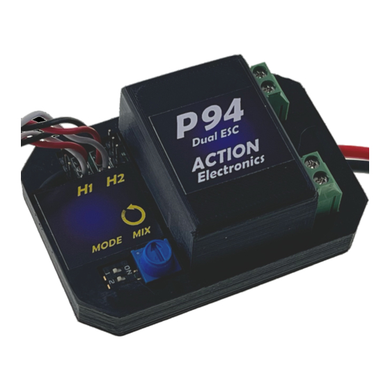
P94 DUAL ESC/MIXER MULTI CONTROLLER
Type: Dual ESC and Mixer Module. Equivalent to two fully operational ESCs and a mixer, all in the same
case. Will suit most types of DC
No of channels required:
Motor voltage:
Maximum continuous current rating:
Modes: 4 different modes of operation, selectable by user via on-board 2-way DIL switches:
Mode 1: Dual electronic speed controllers - Each ESC works from a separate channel i.e. "Tank Steering";
Mode 2: Dual thruster mode - Controls bow and stern thrusters. Skipper selects either Traverse (where
thrusters work in the same direction and slew the model sideways) or Spin (where the
thrusters work in opposite directions and spin the model on its own axis). Selection is done by
"blipping" the rudder stick hard over and letting it go straight away. Both thrusters are also
fully speed-controlled.
Mode 3: 0% - 100% Mixer. As Mode 4, except that inboard motor can be made to spin at full speed in
reverse sense on full rudder command i.e. you can spin the model on its axis.
Mode 4: 0% - 50% Mixer. Applies differential speed control to the motors automatically as a rudder
command is give. Adjustable from 0%, where there is no mixing of rudder and throttle signals,
up to 50%, where the inboard motor just stops at full rudder command.
Other facilities:
Battery Eliminator (BEC)................................ Built in 5V 2A (3A peak) battery eliminator
Autoset..........................................................
Failsafe..........................................................
Central Motor & Rudder connections..............3-pin headers provided for connecting the steering servo and a
Adjustable thruster output............................ Allows the operation of commercial thrusters from higher-
BATT
Receiver
CH2
CH1
(2 Channel Minimum)
Steering Servo
SCHEMATIC OF INSTALLATION IN TWIN-ENGINED MODEL
C 2023 Action R/C Electronics
www.action-electronics.co.uk
brushed
motor used in model boats, including 7+ pole types.
2
6v to 24v
20A per ESC
P94 automatically sets neutral position of throttle and steering
o
n power
ESCs shut down motors on loss of signal.
separate speed controller to operate a centre motor.
voltage main batteries.
T
S
01248 719353
ing
up i.e. No
"binding" or other setting up to do
centre shaft (if required)
ESC for motor on
Main battery
Stb'd Motor
Main battery
Port Motor
Advertisement

Related Manuals for ACTION ELECTRONICS P94


Summary of Contents for ACTION ELECTRONICS P94
- Page 1 50%, where the inboard motor just stops at full rudder command. Other facilities: Battery Eliminator (BEC)........ Built in 5V 2A (3A peak) battery eliminator P94 automatically sets neutral position of throttle and steering Autoset............n power up i.e. No “binding”...
- Page 2 This takes power from the main motor battery/batteries and reduces it to 5v to operate the logic circuit in P94 and to feed the power to the receiver, also @ 5v. Unless you want to run the receiver from a seperate battery (or the flylead from P92/P102/P107) then you MUST remove the red wires from the two leads marked T and S.
-
Page 3: Modes Of Operation
6. If your transmitter has any form of inter-channel mixing on the steering and throttle channels, make sure it is switched OFF for the operation of a model fitted with a P94. Also ensure that any servo throw adjustment is set to 100% movement in both directions. See the manual for your radio for further information. - Page 4 ‘bind’ - the relays will click rapidly several times and it is then OK to operate the transmitter as normal. If the model goes out of range then P94 will stop both of the motors, but when the model comes back into range then P94 will resume with the same neutral positions that it had when you first switched on i.e.
- Page 5 www.action-electronics.co.uk FIG #1: TYPICAL TWIN MOTOR CONNECTIONS (MODES 1, 3 &4) (Power connections omitted for clarity) "+ve" MOTOR #1 STARBOARD MOTOR #2 PORT ACTion P95/2 Indicator "+ve" Fuse Board ACTion RFI Suppressor Kit When connected as shown, the LEDs will both glow the same colour when the main drive motors rotate in opposite direction e.g.
- Page 6 40 Amp connector Black 6v - 24v battery This wiring layout may also be used for a P94 Lite installation. Motor current should not exceed 10A each and a 20A fuse (max) should be used. FIG #3: BASIC INSTALLATION WITH SINGLE BATTERY (Receiver &...
- Page 7 P94 "T" P94 "S" Spin/Slew Select = RH stick Side/Side Speed & Direction = LH stick Side/Side Connect Steering Servo to H1 on P94 “Blip” Tx stick to Left < 1 second to change from Spin to Slew mode and to the Right to MODE 2 change back.
- Page 8 8 MODES 3/4; 100% & 50% MIXERS RECEIVER CONNECTIONS FOR MODES 3 and 4 (Futaba convention for Page 4 numbering channels is shown) P94 "T" connector P94 "S" connector Steering = RH stick Side/Side Throttle = LH stick Up/Down STOP...
Need help?
Do you have a question about the P94 and is the answer not in the manual?
Questions and answers