
Related Manuals for HydroAir EC7000 Series

Summary of Contents for HydroAir EC7000 Series
- Page 1 Edition Operations Manual EC7000 & EC700 series Conductivity/ Resistivity / Salinity / TDS Analyzer EC7000 EC700...
-
Page 3: Table Of Contents
Table of Content Hydro-Air EC7000 & EC700 Table of Content Table of Content ..................... I Specifications ..................... 1 Introduction ....................2 2.1. General Information ................2 2.2. Safety Information ................2 2.3. Safety Precautions ................3 2.3.1. Handling By Authorized Personnel ........3 2.3.2. -
Page 4: Table Of Content
Table of Content Hydro-Air EC7000 & EC700 6.2. Temperature ..................19 6.3. Current Output A ................20 6.4. Current Output B ................21 6.5. Relay Output A ................. 22 6.6. Relay Output B ................. 23 6.7. Multifunctional Relay ................ 24 6.8. -
Page 5: Specifications
Specifications Hydro-Air EC7000 & EC700 Specifications Specifications are subjected to change without notice. DETAILS SPECIFICATIONS Conductivity Resistivity Salinity Measuring Range 0 to 20.000 uS/cm 0 to 20.00 0 to 0 to 0 to 20.00 uS/cm MΩ-cm 133,000 78.00 g/kg 0 to 200.0 uS/cm 0 to 2,000 uS/cm 0 to 20.00 mS/cm 0 to 200.0 mS/cm... -
Page 6: Introduction
Introduction Hydro-Air EC7000 & EC700 Introduction This section provides general information about EC7000 and EC700. 2.1. General Information Notice Indicates essential information regarding operation, calibration or anything which is considered as good practice or handling of the products. The manufacturer will not be liable and responsible for any direct, indirect, incidental, or consequential damages due to any defect or omission in the operations manual. -
Page 7: Safety Precautions
Introduction Hydro-Air EC7000 & EC700 2.3. Safety Precautions It’s vitally important to take safety precautions during the installation, operation and calibration of sensors and controllers. Safety must not be compromised; some ground rules need to be observed. The basic guidelines regarding the safe handling of electrical components are documented below and will help users while working with electricity. -
Page 8: Product Overview
Product Overview Hydro-Air EC7000 & EC700 Product Overview 3.1. Product Content The EC7000 and EC700 series packaging contains 1 x controller, 1 x printed manual, 1 x quality control form and a panel mounting kit. 3.2. Dimensions 7000 series: The instrument can be installed into control panel, wall, and pipes. For panel mounting, allocate a 138mm x138mm square cutout, insert the controller then screw the fixed holder. - Page 9 Product Overview Hydro-Air EC7000 & EC700 Figure 2. 7000 Series Panel Installation Exploded View. Side View Bottom View Figure 3. 7000 Series Side and Bottom View. Conductivity / Resistivity / Salinity / TDS Analyzer...
- Page 10 Product Overview Hydro-Air EC7000 & EC700 Figure 4. 7000 Series Wall and Pipe Installation. Conductivity / Resistivity / Salinity / TDS Analyzer...
- Page 11 Product Overview Hydro-Air EC7000 & EC700 700 series: The instrument can be installed into the control panel. Allocate a 92mm x 92mm square cutout, insert the controller then screw the fixed holder. Panel Cut-out Front View Figure 5. 700 Series Panel Cut Out and Front View. Back View Side View Figure 6.
-
Page 12: Installation
Installation Hydro-Air EC7000 & EC700 Installation This part describes the installation of the controller and the connection of the unit to a power source and auxiliary equipment. Wiring Installation The specified performance of the controller is entirely dependent on correct installation. -
Page 13: Connection Label (7000 Series)
Installation Hydro-Air EC7000 & EC700 4.1.1. Connection Label (7000 series) Figure 7. Connection label to EC7000 (90~260VAC power supply) controller. Figure 8. Connection label to EC7000-DC (24 VDC power supply) controller. Conductivity / Resistivity / Salinity / TDS Analyzer... -
Page 14: Connection Label (700 Series)
Installation Hydro-Air EC7000 & EC700 4.1.2. Connection Label (700 series) Figure 9. Connection label to EC700 (90~260VAC) controller. Figure 10. Connection label to EC700 (24VDC power supply) controller. Conductivity / Resistivity / Salinity / TDS Analyzer... -
Page 15: Sensor Connection
The conductivity measurements are strongly affected by the temperature of the sample. Hence, temperature electrode (Pt 1000 or NTC 30K) functions as temperature compensation. Figure 11. EC7000 series: Connection figure for 2-Electrode Sensor. Figure 12. EC700 series: Connection figure for 2-Electrode Sensor. Conductivity / Resistivity / Salinity / TDS Analyzer... -
Page 16: 4-Electrode Sensor
The conductivity measurements are strongly affected by the temperature of the sample. Hence, temperature electrode (Pt 1000 or NTC 30K) functions as temperature compensation. Figure 13. EC7000 series: Connection figure for 4-Electrode Sensor. Figure 14. EC700 series: Connection figure for 4-Electrode Sensor. Conductivity / Resistivity / Salinity / TDS Analyzer... -
Page 17: User Interface
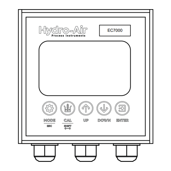
User Interface Hydro-Air EC7000 & EC700 User Interface 5.1. Front Screen WARNING! Before proceeding, ensure that the installation instructions have been followed correctly. Failure to do so may result in an electrically hazardous installation or irreparable damage to the instrument. EC7000 and EC700 are accompanied by five control buttons whose function varies depending upon which screen the user is viewing. - Page 18 User Interface Hydro-Air EC7000 & EC700 Figure 15. Keypad and front panel overview. DESCRIPTION Controller display MODE / ESC key. From the Operation screen, press MODE to enter the Main Menu for operation configurations. Press ESC to navigate back to the previous page.
- Page 19 User Interface Hydro-Air EC7000 & EC700 Figure 16. Screen interface. DESCRIPTION Operation status Count down timer for multifunctional relay (cycle time, clean time, delay time) Measurement value Temperature and unit Relay A status Relay A deenergized Relay A energized Relay B status Relay B deenergized Relay B energized Multifunctional...
-
Page 20: Main Menu
User Interface Hydro-Air EC7000 & EC700 5.2. Main Menu To enter the main menu for EC7000 and EC700, press MODE and insert password 0001. *If no password is inserted within 10 minutes, it will return to measurement mode. DISPLAY INFO The first page of the Main Menu displays the following configurations: Measurements... -
Page 21: Advanced Operation
Advanced Operation Hydro-Air EC7000 & EC700 Advanced Operation Advanced operation control is usually deployed optionally and in addition to basic process controls. Basic process controls are designed and built with the process itself, to facilitate basic operation and control requirements. 6.1. - Page 22 Advanced Operation Hydro-Air EC7000 & EC700 Salinity Offset: Parameter value adjustment Range : ±1.00 g/Kg Filter: To average the reading Range : +10 Total Dissolved Solids (TDS) TDS Coeff: Set the TDS conversion factor equivalent to 1μS/cm of conductivity value Range : 0.500 to 1.000 Offset:...
-
Page 23: Temperature
Advanced Operation Hydro-Air EC7000 & EC700 6.2. Temperature DISPLAY FUNCTIONS Main Menu > Temp Mode: Measurements > Temperature Set the mode for temperature compensation Auto : Automatic temperature compensation Manual : Manual temperature compensation Temp Probe: Set the type of temperature probe used (Auto only) Probes : Pt1000 / NTC30K Offset: Temperature value adjustment (Auto only) -
Page 24: Current Output A
Advanced Operation Hydro-Air EC7000 & EC700 6.3. Current Output A DISPLAY FUNCTIONS Go to Main Menu > Current 04.00mA: Outputs > Current Output A Set the value corresponding to 4.00mA output Conductivity : 0.00 to 2,000 mS Resistivity : 0.00 to 20.00 MΩ-cm Salinity : 0.00 to 78.00 g/Kg : 0.00 to 130,000 ppm... -
Page 25: Current Output B
Advanced Operation Hydro-Air EC7000 & EC700 6.4. Current Output B DISPLAY FUNCTIONS 4.00mA: Go to Main Menu > Current Set the temperature value corresponding to Outputs > Current Output B 4.00mA output 20.00mA: Set the temperature value corresponding to 20.00mA output Note: The minimum difference between 4.00mA and 20.00 mA at least is 10.0 Offset:... -
Page 26: Relay Output A
Advanced Operation Hydro-Air EC7000 & EC700 6.5. Relay Output A DISPLAY FUNCTIONS Go to Main Menu > Relay Status: Outputs > Relay Output A Enable / Disable Relay A Activate: Set point value to energize Relay A Conductivity : 0.00 to 20.00 / 20.00 / 200.0 / 2,000 μS : 0.00 to 20.00 / 200.0 / 2,000 mS Resistivity... -
Page 27: Relay Output B
Advanced Operation Hydro-Air EC7000 & EC700 6.6. Relay Output B DISPLAY FUNCTIONS Go to Main Menu > Relay Status: Outputs > Relay Output B Enable / Disable Relay B Activate: Set point value to energize Relay B Conductivity : 0.00 to 20.00 / 20.00 / 200.0 / 2,000 μS : 0.00 to 20.00 / 200.0 / 2,000mS Resistivity... -
Page 28: Multifunctional Relay
Advanced Operation Hydro-Air EC7000 & EC700 6.7. Multifunctional Relay DISPLAY FUNCTIONS Go to Main Menu > Relay Status: Outputs > Multifunctional Relay Enable / Disable Relay Cycle Time: Set the total time per cycle. Range : 0.1 to 999.9 hour Clean Time: Set the operation period of clean. -
Page 29: Rs-485 Output
Advanced Operation Hydro-Air EC7000 & EC700 6.8. RS-485 Output DISPLAY FUNCTIONS Go to Main Menu > RS485 Output ID Address: Set the ID Address for RS-485 Modbus protocol ID Address : 001 to 255 Baud Rate: Set the Baud Rate Options : 9600 / 19200 / 38400 6.9. -
Page 30: View Data Logging
Advanced Operation Hydro-Air EC7000 & EC700 6.10. View Data Logging DISPLAY FUNCTIONS Go to Main Menu > Data Logging Select View Data Logging at the Data Logging > View Data Logging menu to enter record query mode. Press UP, DOWN or SHIFT to key in the record number. -
Page 31: Extract Data Logging
Advanced Operation Hydro-Air EC7000 & EC700 6.11. Extract Data Logging DISPLAY FUNCTIONS Go to Main Menu > Data Logging Download Records: > Extract Data Logging To download records, plug in a USB flash disk into the USB port and then download all the records. It takes around 10 minutes to download 500,000 records at the speed around 50,000 data/minute. -
Page 32: Date & Time
Advanced Operation Hydro-Air EC7000 & EC700 6.13. Date & Time DISPLAY FUNCTIONS Go to Main Menu > General Press UP / DOWN key to set the date. Setting > Date & Time Clock will continue to run for about 1 week after power down. -
Page 33: Display Settings
Advanced Operation Hydro-Air EC7000 & EC700 6.15. Display Settings DISPLAY FUNCTIONS Go to Main Menu > General Contrast: Setting > Display Setting Adjust the contrast of the screen. Range : 0 to 10 Back Light: Auto: The backlight will turn off after 60 seconds without being pressed. -
Page 34: Software Version
Advanced Operation Hydro-Air EC7000 & EC700 6.17. Software Version DISPLAY FUNCTIONS Go to Main Menu > General Displays the current version of controller’s Setting > Software Version Software (SW) and Hardware (HW) 6.18. Factory Reset DISPLAY FUNCTIONS Go to Main Menu > General Reset: Setting >... -
Page 35: Calibration
Calibration Hydro-Air EC7000 & EC700 Calibration Calibration of sensors is very important in maintaining high performance and accurate readings. The controller features calibration settings to calibrate the sensors associated with the controller. Calibration of conductivity sensors with temperature as the correction variable Conductivity measurements are strongly affected by the temperature of the standard buffer. -
Page 36: Parameters Setting
Calibration Hydro-Air EC7000 & EC700 7.2. Parameters Setting DISPLAY FUNCTIONS Select Parameter Setting to adjust the Go to Main Menu > Calibration > temperature coefficient at which a solution’s Parameters Setting or press CAL conductivity increases with an increase of button >... -
Page 37: Calibration
Calibration Hydro-Air EC7000 & EC700 7.3. Calibration One test container with standard conductivity buffer solution is required for calibration. The conductivity of the chosen standard buffer must be within the operating range of the sensor. DISPLAY FUNCTIONS Select Calibration to start calibration by adjusting Go to Main Menu >... -
Page 38: Calibration Reset
Calibration Hydro-Air EC7000 & EC700 TDS calibration page Salinity calibration page 7.4. Calibration Reset DISPLAY FUNCTIONS Go to Main Menu > Calibration > Reset: Reset Parameter or press CAL Resets all calibration settings back to factory button > Reset Parameter. settings. -
Page 39: Rs-485 Command
RS-485 Command Hydro-Air EC7000 & EC700 RS-485 Command 8.1. Connections The controller connects to the RS-485 Modbus RTU via the RS485A (Slot 8) and RS485B (Slot 9) for EC7000 and RS485A (Slot 12) and RS485B (Slot 13) for EC700. Please make sure the connection is correct to the corresponding slots at the terminal block. -
Page 40: Start Address
RS-485 Command Hydro-Air EC7000 & EC700 8.3. Start Address ADDRESS DESCRIPTION DATA Command 04 0x00 EC/RES/SAL/TDS reading Reading: Floating, the unit is uS 0x01 EC/RES/SAL/TDS current Reading: X0.01 0x02 Temperature Reading: X 0.1 0x03 Temperature Current Reading: X0.01 0x04 Error code Reading: X1 0x09 Model type... - Page 41 RS-485 Command Hydro-Air EC7000 & EC700 0x20 Relay B EC deactivation point Reading:X0.01/0.1/1 0x21 Relay B RES activation point Reading:X0.01 0x22 Relay B RES deactivation point Reading:X0.01 0x23 Relay B SAL activation point Reading:X0.01 0x24 Relay B SAL deactivation point Reading:X0.01 0x25 Relay B TDS1 activation point...
-
Page 42: Error Code
RS-485 Command Hydro-Air EC7000 & EC700 8.4. Error Code ERROR CODE TYPE OF ERROR Error 01 Memory error Error 02 Reading is over maximum Error 03 Reading is under minimum Error 04 Temperature is over maximum Error 05 Temperature is under minimum Error 06 Current Output A is over 20.5mA. - Page 43 RS-485 Command Hydro-Air EC7000 & EC700 Relay A RES activate point 10.00 M Ω Range: 0.00-20.00 Relay A RES deactivate point M Ω Range: 0.00-20.00 Relay A SAL activate point 10.00 g/Kg Range: 0.00 – 78.00 Relay A SAL deactivate point g/Kg Range: 0.00 –...
- Page 45 RS-485 Command Hydro-Air EC7000 & EC700 Conductivity / Resistivity / Salinity / TDS Analyzer...
Need help?
Do you have a question about the EC7000 Series and is the answer not in the manual?
Questions and answers