Table of Contents
Advertisement
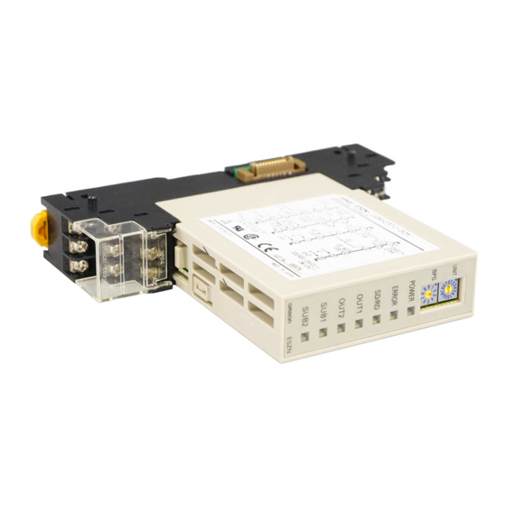
Modular Temperature Controller
E5ZN
New DIN Track Mounting Temperature
Controller
• Two channels of temperature control available despite width of
only 22.5 mm.
• The Temperature Controller itself can be replaced without
changing terminal wiring.
• Use in combination with a compact Setting Display Unit to
reduce communications programming requirements.
• A wide variety of operation indicators (single-color LEDs)
enable easy operation monitoring.
• Power supply and communications wiring not required between
Units when mounted side-by-side.
Model Number Structure
■ Model Number Legend
E5ZN- 2 @ @ @ @ @ -FLK
1 2
3
4
5
6
1. Control points
2:
Two points
2. Control output
Q:
Voltage (for driving SSR)
T:
Transistor
C:
Current
3. Auxiliary output
P:
Transistor (sourcing)
N:
Transistor (sinking)
4. Option
H:
Heater burnout alarm
F:
Transfer output
5. Communications
03:
RS-485
6. Input type
TC:
Thermocouple
P:
Platinum resistance thermometer
7. CompoWay/F serial communications
-FLK: CompoWay/F serial communications
7
Modular Temperature Controller
®
E5ZN
I-129
Advertisement
Table of Contents

Subscribe to Our Youtube Channel
Related Manuals for Omron E5ZN


Summary of Contents for Omron E5ZN
- Page 1 22.5 mm. • The Temperature Controller itself can be replaced without changing terminal wiring. • Use in combination with a compact Setting Display Unit to reduce communications programming requirements. • A wide variety of operation indicators (single-color LEDs) enable easy operation monitoring.
-
Page 2: Ordering Information
Note: 1. Terminal Units are required for wiring. Purchase separately. 2. When connecting the load of the controlled system, heat control output or cool control output can be allocated to the control output or auxiliary output. When connecting a recording device or Digital Panel Meter, transfer output can be allocated to control output or auxiliary output 3 or 4 of analog output models. -
Page 3: Specifications
Approx. 3 W Thermocouple: K, J, T, E, L, U, N, R, S, B Infrared temperature sensor (ES1A series): 10 to 70×C, 60 to 120×C, 115 to 165×C, 160 to 260×C (See note 1.) Sensor input Voltage input: 0 to 50 mV Platinum resistance thermometer: Pt100, JPt100 Output voltage: 12 VDC ±15% (PNP);... - Page 4 200×C max. is 3×C 1 digit max. 2. The transfer output accuracy for 0 to 4 mA when 0 to 20 mA DC is selected is 0.5% FS 0.7 mA. The transfer output accuracy for 0 to 1 V when 0 to 5 VDC is selected is 0.5% FS 0.175 V.
- Page 5 2. If the heater burnout alarm setting is set to 0.0 A, the alarm ity can all be set independently as host communications set- is always OFF, and if it is set to 50.0 A the alarm is always tings.
- Page 6 SUB2 SUB2 (Auxiliary Output 2) Lights when the auxiliary output 2 is ON. E5ZN-SDL The following diagram shows the names and functions of the E5ZN-SDL parts for when it is connected to the E5ZN-2 @@@@@@@ Operation Indicators Temperature Unit No. 1 Display •...
-
Page 7: End Plate
Units. purchase the first Unit together with the E5ZN-SCT24S-500. Note: Refer to the following manual for precautionary information and other information necessary to use the E5ZN: E5ZN Modular Temperature Controller User’s Manual (Cat. No. H113). End Plate... - Page 8 +1.0 No. of Units – 2.5) 14.2 63.7 +0.6 • The mounting panel thickness is 1 to 5 mm. • Vertical side-by-side mounting is not possible. (Allow sufficient space above and below.) • When mounting several Units, make sure that the ambient tem-perature specifications are not exceeded.
-
Page 9: Installation
(Doing so may result in temperature measurement errors due to unwanted current paths.) • There is basic insulation between the power supply inputs and outputs for this product. If reinforced insulation is required, connect the input and output terminals to equipment without any exposed charge-carrying parts, or to equipment with basic insulation sufficient for the maximum oper- ating voltage of the power supply and the inputs and outputs. -
Page 10: Operation
This symbol indicates setting data that is displayed only for models with pulse output. Communications sdwt ("Models with pulse output" is used here to indicate models with voltage output or transistor output.) response wait time This symbol indicates setting data that is displayed only for models with analog output. - Page 11 1 s min. Key is pressed for 1 s max. Setting change wtpt protection Power ON @ Key, 1 s min. 1 s min. Operation level Adjustment level @ Key, 1 s min. 3 s min. AT execute/cancel Cooling coefficient...
-
Page 12: Transfer Output Scaling
(4 to 20 mA DC or 0 to 20 mA DC for control out- Process Meter puts 1 and 2, and to 1 to 5 VDC or 0 to 5 VDC for auxiliary outputs K3MA-J 24 VAC/VDC 3 and 4). -
Page 13: Definition Of Precautionary Information
• Locations subject to dust or corrosive gases (in particular, sul- !WARNING fide gas and ammonia gas) Do not touch any of the terminals while the power is ON. Doing so • Locations subject to freezing or condensation may result in electric shock. -
Page 14: Mounting And Dismounting
• Mount the E5ZN at least 30 mm away from other devices to ensure easy mounting and dismounting. Note: Refer to the following manual for precautionary information and other information necessary to use the E5ZN: E5ZN Temperature Controller Operation Manual (Cat. No. H113). -
Page 15: Warranty And Limitations Of Liability
Warranty and Limitations of Liability ■ WARRANTY OMRON's exclusive warranty is that the products are free from defects in materials and workmanship for a period of one year (or other period if specified) from date of sale by OMRON. OMRON MAKES NO WARRANTY OR REPRESENTATION, EXPRESS OR IMPLIED, REGARDING NON-INFRINGEMENT, MERCHANTABILITY, OR FITNESS FOR PARTICULAR PURPOSE OF THE PRODUCTS. - Page 16 ALL DIMENSIONS SHOWN ARE IN MILLIMETERS. To convert millimeters into inches, multiply by 0.03937. To convert grams into ounces, multiply by 0.03527. In the interest of product improvement, specifications are subject to change without notice. Cat. No. H116-E1-02A E5ZN I-144...
Need help?
Do you have a question about the E5ZN and is the answer not in the manual?
Questions and answers