Advertisement
Quick Links
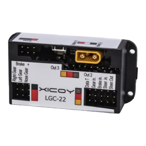
Electric Landing Gear controller and sequencer
LGC 22
Users Guide.
Plaça Pere Llauger I Prim, nau 18. 08360, Canet de Mar, Barcelona, Catalonia, Spain
E-mail: sales@xicoy.com. Fax: +34 93 794 27 74 web:
www.xicoy.com
© Copyright 2022, Xicoy Electronica SL. All Rights Reserved
Manual contents & design: Gaspar Espiell
-0-
Advertisement

Related Manuals for Gaspar XICOY LGC 22

Summary of Contents for Gaspar XICOY LGC 22
- Page 1 Users Guide. Plaça Pere Llauger I Prim, nau 18. 08360, Canet de Mar, Barcelona, Catalonia, Spain E-mail: sales@xicoy.com. Fax: +34 93 794 27 74 web: www.xicoy.com © Copyright 2022, Xicoy Electronica SL. All Rights Reserved Manual contents & design: Gaspar Espiell...
- Page 2 Welcome! Congratulations on the purchase of your new landing gear controller. Xicoy are dedicated to the design and production of electronic controllers to the highest standards of quality and reliability to bring you the customer the very latest next generation designs. Features -Direct control of 3 motors in bidirectional and regulated mode up to 2,5 A.
-
Page 3: Please Read
The polarity of the connection lead is marked on the label of the unit. In the case of using reversed gears, the connector should be connected backwards to reverse the operation of the motors. Brake connections Picture 2 Connect the leads from brakes on the sockets labeled “Brake”. Polarity and position are not important on the brakes. - Page 4 This controller can receive up to 3 different power sources. In order to prevent malfunctions in your system you should know that: The main battery should be between 6,6 to 9,9V. Recommended battery is a Lipo of 7,4V. Please double check the polarity before connecting it. The damage caused by polarity reversal is not covered by warranty!!! This battery powers the motors and the brakes.
- Page 5 SETUP Once you have installed the controller in your model, you can adjust the radio, outputs, delays and steering servo. Setup can be done trough a data terminal or trough a pushbutton and LED light. Full functions are only available if programmed trough the data terminal. In both cases, first of all you should decide if you will use one or two channels for control and then setup your transmitter accordingly.
- Page 6 “140”. You can check that, when operating the transmitter, the reading change accordingly. On third screen you can scroll trough the different programming sections. Select the area you want to program by pressing the “+” button. Radio Setup On this section you can program the radio inputs to mach your transmitter and setup the brake power.
- Page 7 maximum power. Press the “+” button. The controller will store the current signal received as “Brake 100%” command”. This completes the radio setup for the gear and brake channels. But two more adjust options are offered in this section: 1. Brake limiter: The limiter usually is set at 100% and the brake power is adjusted trough the TX, but in the case that you need to limit the maxim brake power, you can decrease this setting to reduce the power applied to brakes.
- Page 8 servo1 OUT When this screen is displayed, the will deliver the same signal as arriving to the Steering input, so that you can move the servo directly trough the rudder stick on your TX. Set the servo at the position you want that it to be when the gear is retracted, and press the “+”...
- Page 9 After the movement of retracts is finished, the servo signal is switched off, that cause the servo to act as “unpowered”. The servo position is refreshed each 15 seconds to compensate the small movement of the servo (if any) during these 15s to keep the door in to commanded position, assuming that there is not a considerable force acting on the servo during the switch off period.
- Page 10 If you use same signal as the rudder, first setup the rudder centering and travel. Once you are satisfied with the rudder operation, connect the steering servo and proceed to adjustment. First adjustment is the position of the steering servo at retracted position. Using the rudder channel of your TX, set the servo to the position you want it when the gear is being retracted and stored.
- Page 11 on the gears, bearings and suspension. Too low time will not unload the motor, causing high stress and wear; too long time can move the slider out of “lock” position. Last adjustable parameter is the “Maximum Motor time”. This is a security parameter that will power down the motors after a certain operation time (programmable) to prevent the case that the endpoint is undetected.
- Page 12 Leave the main battery disconnected to prevent accidental movement of motors. Switch off the power. Press the button with the aid of a plastic rod (a pen, etc, but nothing metallic that could damage the electronic board). While the button pressed, switch on the power on the receiver.
Need help?
Do you have a question about the XICOY LGC 22 and is the answer not in the manual?
Questions and answers