Table of Contents
Advertisement
Quick Links
Advertisement
Table of Contents

Related Manuals for Trademaster LIZARD

Summary of Contents for Trademaster LIZARD
- Page 1 LIZARD WELDING CARRIAGE OPERATOR’S MANUAL BEFORE USE, ENSURE EVERYONE USING THIS MACHINE READS AND UNDERSTANDS ALL SAFETY AND OPERATING INSTRUCTIONS IN THIS MANUAL . Serial #..........Date of Purchase......
-
Page 2: Table Of Contents
TRADEMASTER LIZARD WELDING CARRIAGE IMPORTED & DISTRIBUTED BY INDUSTRIAL TOOL & MACHINERY SALES 18 BUSINESS ST YATALA QLD 4207 AUSTRALIA INDUSTRIAL TOOL 07 3287 1114 07 3287 1115 sales@industrialtool.com.au www.industrialtool.com.au WARRANTY TERMS In addition to any warranties or conditions implied by applicable Statute or Regulations, Industrial Tool & Machinery Sales warrants all of it’s products against defective workmanship and faulty materials for a period of twelve (12) -
Page 3: General Information
1.1. Application The LIZARD Welding Carriage is designed to produce continuous or intermittent welds using MIG/MAG torches with handle diameter in 16–25 mm range (0.63–0.98’’). The machine can work in PA, PB, PC, and PF welding positions. It is fixed by permanent magnets and contains four wheel drive with speed adjustment. - Page 4 GENERAL INFORMATION Welding position ~ 115–230 V, 50–60 Hz Power 25 W Welding position horizontal PA (flat), PB (horizontal vertical), PC (horizontal) vertical PF (vertical up) Minimum path convex radius 1500 mm (60’’) Minimum path concave radius 1500 mm (60’’) Torch type MIG/MAG Torch diameter...
-
Page 5: Technical Data (With Oscillator)
GENERAL INFORMATION 1.3. Technical data (with oscillator) Oscillation type angular (maximum 11º) Oscillation amplitude for r=150 mm 1–30 mm (1–100%) (5.9’’) Oscillation speed for oscillation 7–164 cycles/min (1–100%) amplitude of 10 mm (0.4’’) and zero delay on tips Delay on tips 0–5 s Maximum torque 5 Nm (3.7 lb•ft) -
Page 6: Design
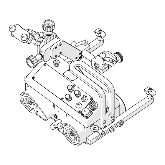
GENERAL INFORMATION 1.4. Design The LIZARD welding carriage contains a drive system with controller, cross slides, two follower arms, cable holder, and torch holder. The drive system comprises a gear motor that drives four rubber wheels of high thermal resistance. -
Page 7: Equipment Included
Travel Direction Switch (left / 0 / right) Figure 2. Control panel design 1.5. Equipment included The LIZARD welding carriage is supplied with complete standard equipment in foam filled cardboard box. The included equipment consists of: • Welding Carriage – 1 unit •... -
Page 8: Safety Precautions
SAFTEY PRECAUTIONS 2. SAFETY PRECAUTIONS Before start, read Operator’s Manual and complete proper occupational safety and health training. Machine must be used only in applications stated in Operator’s Manual. Machine must be complete and all parts must be genuine. Power supply specifications must conform to those stated on rating plate. Power supply socket must be equipped with grounding pin. - Page 9 SAFTEY PRECAUTIONS Perform all maintenance work only with power cord unplugged from power socket. Perform all repairs only in service centre appointed by seller. If machine falls on hard surface, from height, is wet, or has other damage that could affect technical state of machine, stop operation and immediately send machine to service centre for inspection.
-
Page 10: Startup And Operation
STARTUP AND OPERATION 3. STARTUP AND OPERATION WARNING! Read safety precautions before starting. 3.1. Preparation Use carrying handle (Figure 3) for transportation and positioning at the worksite. Set all levers to position “0”: power switch, magnetic unit lever, arc ignition switch, and travel direction switch. Knobs securing Cable Cable Holder into Holder... - Page 11 STARTUP AND OPERATION Plug the cord into power supply socket. Put a torch into the torch holder and secure with the knob. Then, put the torch cable into the cable holder, secure it with the knobs, and fix the holder in a proper position using the levers.
-
Page 12: Startup
3.3. Programming The LIZARD welding carriage is equipped with a programming device that enables to define up to 40 welding programs. After you enter into the configuration menu, proceed as described in the Figure 6 to move among the parameters from the Table 1. -
Page 13: Welding Procedure
“Load setup” 1 - 40 Pressing knob F2 loads the configuration saved under the indicated program number. “Language” ENGLISH POLISH Language of the menu SPANISH FRENCH PORTUGUESE TURKISH Table 1. Settings available in basic version of LIZARD welding carriage... -
Page 14: Operation
STARTUP AND OPERATION 3.5. Operation If the machine is to control a torch, toggle the arc ignition switch to position “I”. To check whether the arc ignition cable is connected correctly, toggle the switch to position “TEST”. WARNING: If the arc ignition switch is set to position “I”, the torch starts welding immediately after choosing a travel direction. -
Page 15: Using Oscillator (Optional Equipment)
STARTUP AND OPERATION 3.6. Using oscillator (optional equipment) 3.6.1 Installation Mount the oscillator according to the following instructions. • Disassemble torch holder (1). • Disassemble torch plate (2) by unscrewing bolts (3). • Unscrew cap (4). • Fix arm (5) to oscillator (6). •... -
Page 16: Welding With Oscillation
STARTUP AND OPERATION 3.4.2. Welding with Oscillation Once the oscillator is connected to the LIZARD welding carriage, several new settings appear in the menu (Table 2). Welding with the oscillation is performed in a standard manner, however, the welds form a shape similar to the shape shown in the Figure 8 instead of a straight line from the Figure 7. -
Page 17: Operation
STARTUP AND OPERATION 3.6.3. Operation Operating the LIZARD welding carriage with connected oscillator is performed similarly to operating without the oscillator. During welding with oscillator, the menu indicated in the Figure 9 shows up on the display. Rotation of the knob F1 changes the oscillation amplitude by 1%. -
Page 18: Wiring Diagram
WIRING DIAGRAM... -
Page 19: General Assembly
TORCH PLATE COMPLATE WSP-0476-05-00-00-0 2355 SLIDE BRACKET UCW-0476-07-00-00-0 2358 CABLE ANCHOR ASSEMBLY WOZ-0476-11-00-00-0 2359 DRIVE SYSTEM ASSY TBL-0476-15-01-02-0 NAME PLATE "Lizard" UCW-0476-20-00-00-0 2361 TORCH HOLDING ASSY ZSP-0466-03-00-00-0 2062 CROSS SLIDES ASSY KUL-0466-13-00-00-0 2143 BALL LEVEL NIT-000010 ROUND HEAD RIVET 2x6... - Page 20 GENERAL ASSEMBLY...
-
Page 21: Control Panel Assembly
CONTROL PANEL ASSEMBLY PNL-0476-02-02-00-1 CONTROL PANEL ASSEMBLY ITEM PART NUMBER VERSION DESCRIPTION Q-TY USZ-0476-02-02-01-0 PANEL PLATE SEAL MSK-0476-02-02-10-0 2384 PANEL PLATE ASSY 4.2.2 NKL-0476-15-01-01-0 PANEL PLATE LABEL MDL-0476-02-02-20-1 ELECTRONIC CONTROLLER COMPLATE 4.3.1 MDL-0476-02-02-22-0 DISPLAY MODULE, 4.3.2 SRB-000307 PLASTIC SCREW M3x5 MDL-0476-02-02-30-1 ENCODER MODULE, PKT-000016... -
Page 22: Torch Plate & Cable Anchor Assemblies
TORCH PLATE & CABLE ANCHOR ASSEMBLIES PLY-0476-03-00-00-0 TORCH PLATE ASSEMBLY ITEM PART NUMBER VERSION DESCRIPTION Q-TY LCZ-0476-03-01-00-0 2389 PLATE KST-0466-05-02-00-0 2106 BLOCK PLATE SRB-000174 HEX. SOCKET BOLT M5 x 16 RKJ-000036 HANDLEVER GN 300-45-M6-32-SW, UCW-0476-07-00-00-0 CABLE ANCHOR ASSEMBLY ITEM PART NUMBER VERSION DESCRIPTION Q-TY... -
Page 23: Drive System Assembly
DRIVE SYSTEM ASSEMBLY WOZ-0476-11-00-00-0 DRIVE SYSTEM ASSEMBLY ITEM PART NUMBER VERSION DESCRIPTION Q-TY ZSP-0476-01-00-00-0 2395 DRIVE SYSTEM PKR-0476-02-00-00-0 2396 CONTROLLER HOUSING COMPLATE PRW-0476-04-00-00-0 2397 FOLLOWER ASSEMBLY, SRB-0476-08-00-00-0 FOLLOWER SCREW, USZ-0476-09-00-00-0 SEAL SRB-000278 EYE BOLT M6DIN 580 WKR-000066 SOCKET SET SCREW M6x10... -
Page 24: Drive System
DRIVE SYSTEM ZSP-0476-01-00-00-0 DRIVE SYSTEM ITEM PART NUMBER VERSION DESCRIPTION Q-TY 8.1.1 KRP-0476-01-01-00-1 2402 FRAME, 8.1.2 WLK-0476-01-02-00-0 FRONT DRIVE SHAFT ASSY, 8.1.3 WLK-0476-01-03-00-0 BACK DRIVE SHAFT ASSY, 8.1.4 BLO-0476-01-04-00-0 2433 MAGNET BLOCK ASSEMBLY 8.1.5 NPN-0476-01-05-00-0 CHAIN TENSIONER 8.1.6 RDK-0476-01-06-00-0 GEAR CASE ASSEMBLY, 8.1.7 KOL-0476-01-07-00-0 2252... - Page 25 DRIVE SYSTEM...
-
Page 26: Controller Housing Assembly
CONTROLLER HOUSING ASSEMBLY PKR-0476-02-00-00-0 CONTROLLER HOUSING ASSEMBLY ITEM PART NUMBER VERSION DESCRIPTION Q-TY 1.8.2.1 PKR-0476-02-01-00-1 2400 CONTROLLER HOUSING 1.8.2.2 SZP-0476-02-03-00-0 1.8.2.3 WZK-0476-02-04-00-0 IGNITION WIRE SET 1.8.2.4 WZK-0476-02-06-00-0 OSCILLATION MODULE WIRE SET 1.8.2.5 WZK-0476-02-05-00-0 POWER WIRE SET 1.8.2.6 NKR-000120 SAFETY NUT 1.8.2.7 PDK-000165 LOCKING WASHER 12/19... -
Page 27: Torch Holding Assemblies
TORCH HOLDING ASSEMBLIES UCW-0476-20-00-00-0 TORCH HOLDING ASSEMBLY ITEM PART NUMBER VERSION DESCRIPTION Q-TY 10.1 ZRZ-0466-04-01-00-0 2093 TORCH CLAMP ASSY, 10.2 WLK-0476-20-01-00-0 2710 SHORT TORCH BRACKET ASSY 10.2.1 TLJ-0419-04-02-03-0 INSULATION SLEEVE, 10.2.2 RKJ-000036 HANDLEVER GN 300-45-M6-32- UCW-0476-06-00-00-0 LOW TORCH HOLDING ASSY, ITEM PART NUMBER VERSION...
Need help?
Do you have a question about the LIZARD and is the answer not in the manual?
Questions and answers