Table of Contents
Advertisement
Quick Links
Advertisement
Table of Contents

Subscribe to Our Youtube Channel
Related Manuals for Thermo Scientific Connect Edge

Summary of Contents for Thermo Scientific Connect Edge
- Page 1 Connect Edge User Guide 334314H01 • Revision A • February 2024...
- Page 2 Terms and Conditions of Sale, which Terms and Conditions of Sale shall govern all conflicting information between the two documents. All trademarks recognized. Contents Connect Edge ..............................1 User Guide ................................ 1...
-
Page 3: Table Of Contents
Electrical Warnings ............................... 7 Regulatory Information ........................... 8 Model Numbers, Equipment, and Kits ......................9 Connect Edge Gateway ..............................9 Connect Edge Gateway Kit ............................9 Connect Edge Accessories ............................10 Connect Edge Adapter Kits ............................10 Supported Equipment ..............................10 Technical Specifications .......................... - Page 4 Enroll for Edge Gateway Management ........................37 View /Approve Requests ............................37 Hardware Installation ............................ 37 Installing/Mounting Connect Edge gateway ......................37 Replacing Mounting Bracket with the DIN Rail Mounting Clip ................ 38 Replacing DIN Rail Mounting Clip with Mounting Bracket................39 Attaching Device Adapter ............................
- Page 5 Default Settings ................................ 64 Recommended Network Topologies ........................64 Troubleshooting ............................67 Maintaining your Connect Edge Hardware ....................68 How to safely remove the power supply ........................ 69 How to verify the installation of the product ......................69 How to clean the product ............................69...
-
Page 6: Introduction
Connect Edge adapters provide an interface between 1 laboratory device and a Connect Edge gateway over Wi-Fi or wired Ethernet. This user guide presents an overview of the Connect Edge solution and instructions to help get your system up and running quickly. -
Page 7: Safety Considerations
The Connect Edge gateway must be powered by a 24V DC power supply. The Connect Edge adapters must be powered by a 5V DC power supply or via the PoE Ethernet base. Do not open the Connect Edge gateway and adapters and do not dismantle internal components or modify them in any manner. -
Page 8: Regulatory Information
Do not subject the gateway and adapters to physical shock, as it may cause serious malfunction or damage. Do not use or place the gateway and adapters in a wet or humid location. The Connect Edge gateway and adapters are not waterproof. -
Page 9: Model Numbers, Equipment, And Kits
The wireless device complies with the EU Directive 2011/65/EU (Restriction of the Use of Certain Hazardous Substances in Electronic and Electrical Equipment) and the amendment of (EU) 2015/863. Do not dispose of this product with household trash. Thermo Scientific recycles this product under certain conditions. Contact us for more information. ... -
Page 10: Connect Edge Accessories
EDGEPTGATE07 EDGEKTCELL06 EDGEPTGATE08 Connect Edge Accessories Connect Edge Accessories Description EDGEPTPWRS01 Connect Edge Gateway Power Supply EXT 24V EDGEPTANTD01 Connect Edge Gateway Antenna Dual Band EDGEPTANTC01 Connect Edge Gateway Antenna 4G Cellular EDGEPTINST001 Connect Edge QuickStart Guide Connect Edge Adapter Kits... -
Page 11: Technical Specifications
Technical Specifications Product Dimensions Gateway mechanical dimensions The product electronics are housed in an ABS enclosure having the following dimensions: 139 (L) x 115 (W) x 46 (H); mm - Antennas Connectors and Mounting Bracket included. Gateway mounting bracket mechanical dimensions... -
Page 12: Gateway Din Rail Mounting Bracket Mechanical Dimensions
The Mounting Bracket fastened on the bottom side of the gateway has the following dimensions. Gateway DIN Rail Mounting Bracket mechanical dimensions... -
Page 13: Device Adapter Mechanical Dimensions
DIN rail mounting clip, 48mm width. Clip material: fiberglass reinforced nylon 66. Device Adapter mechanical dimensions... -
Page 14: Adapter Ethernet Base Mechanical Dimensions
Adapter Ethernet Base mechanical dimensions Power Options This product is not provided with any ON/OFF switch. The Power IN connector is the disconnecting means from the power supply. Only use provided power supplies. Gateway power supply specifications Power supply Nominal: 24 VDC; Range: 12 to 24 VDC with Transient Protection Power consumption 2 W idle;... -
Page 15: Getting Started
2. Make sure that the electrical installation is made correctly in compliance with the relevant standards and regulations. Getting Started The following section will detail the necessary steps to setup your Connect Edge gateway. For most activities, you will need: A computer connected to the internet... -
Page 16: Step 2: Register Subscription
(Optional) Install the InstrumentConnect mobile application on your phone or tablet. Log in using the same email and password you created for your Thermo Connect account above. Step 2: Register subscription To access the Gateway Management portal, the user must first register a valid registration key with subscription. -
Page 17: Step 3: Set Up Hardware
Step 3: Set Up Hardware Decide how the gateway will connect to the Internet. The options are: Ethernet 1 (Enabled by default) Wi-Fi Cellular If not connecting with Ethernet 1, network configuration will be needed after the gateway is initialized (Status 1 LED becomes solid). - Page 18 A. Connect the supplied power supply to the gateway through the PWR IN port. B. Once power is provided, STATUS 1 LED on the Connect Edge gateway will blink while the gateway prepares itself. Wait for the Status LED 1 to turn solid green.
- Page 19 Connect Edge PoE Adapter: Option varies by location. Connect to the Internet: The Connect Edge Gateway will attempt to access the Internet after booting. An internet connection is required to complete the remaining steps. The default Ethernet method does not require any configuration changes to be made prior to connection.
-
Page 20: Step 4: Register Gateway
4. Enter the following username and password details. a. Username: admin b. Password: <latest password> (default is the gateway serial number) NOTE: For alternate options to access the local UI refer to Connecting to the Gateway Local UI. Wi-Fi Internet Access 1. -
Page 21: Step 5: Register Devices To Gateway
Step 5: Register Devices to Gateway Your Connect Edge gateway can provide connectivity for 10 or more devices. To prevent overloading the gateway, you should always check to ensure CPU utilization is at or below 75%. Utilization beyond 75% could result in unreliable system operation. - Page 22 Adapter MAC address: Connect Edge adapter MAC address (found on the edge of the adapter) Adapter serial number: Connect Edge adapter serial number (found on the top of the adapter) If using the Direct cable connection you will enter the following information: Serial port: USB 0, USB 1 or USB 2 (which is the side USB port) 6.
- Page 23 8. Click on Initiate Registration. Note: Once the device has been registered successfully the user will get a confirmation notification in the top right-hand corner of the screen. 9. Refresh the page periodically to see the device status change. The status will initially show as Registering and eventually change to Active.
-
Page 24: Step 6: Configure Adapter Network Settings
Note: If there are multiple devices to register, it is recommended to perform all device registrations at this time. Step 6: Configure Adapter Network Settings Note: Once this step has been done, it doesn’t need to be done again if additional adapters will use the same network settings. - Page 25 NOTE: For alternate options to access the local UI refer to Connecting to the Gateway Local UI. For supported settings and network topologies, refer to Networking Guidance 5. Select the Network icon from the left navigation menu. 6. Configure Internet or Local settings (if needed) a.
-
Page 26: Step 7: Apply Adapter Configuration, Mount To Instrument
Descriptions for Network Interface and Gateway Interface settings a. Network Interface: Selects how the adapter connects to the network: i. Wi-Fi: Adapter will connect to the local network using Wi-Fi. ii. Ethernet: Adapter will connect to the local network using the PoE Ethernet base accessory. -
Page 27: Gateway Local Ui (Web Interface)
internet connection on your computer and navigate to www.thermofisher.com/edgelogin (or by using the InstrumentConnect application on your phone/tablet). New device connections After logging in to your Thermo Fisher Connect account, your new devices will now be visible in your Instrument dashboard which can be accessed by selecting Instruments>Connected Instruments from the hamburger menu at the left. -
Page 28: Connecting To The Gateway Local Ui
Connecting to the Gateway Local UI You may change connection preferences for your adapters and gateways at any time. There are four ways to access your gateway local UI as displayed in prior steps. Connecting via the ETH 0 port: 1. -
Page 29: View Devices
View devices On logging into the local UI, the home screen will list all devices registered to the gateway and their current registration status. Configure Network Settings Network settings is used to configure gateway network interface settings and to configure the network settings that will be applied to the adapter (if used). -
Page 30: Access Logs
The report can be downloaded using Access logs There are several types of logs that can be accessed using the local UI: System Logs Operational Logs Access Logs Error Logs Debug Logs For all log types except for Debug logs, filters and column selections can be applied to customize the logs displayed on the screen. -
Page 31: Gateway Management
the password. Multiple accounts can be created. Gateway Management Gateways – Monitor a Fleet or Individual Gateways View the health of all gateways and detailed health about individual gateways. 1. Log in to Thermo Fisher Connect Gateway Management via www.thermofisher.com/gatewaymanager 2. -
Page 32: Gateway - Devices
Gateway – Devices View, register, and de-register devices. View and edit device details. 1. Log in to Thermo Fisher Connect Gateway Management via www.thermofisher.com/gatewaymanager. 2. On the Gateway Management screen, locate the appropriate gateway and click the gateway serial number. 3. -
Page 33: Gateway - Logs
Gateway – Diagnostics Run hardware and software diagnostics on the gateway and cloud. 1. Log in to Thermo Fisher Connect Gateway Management via www.thermofisher.com/gatewaymanager. 2. On the Gateway Management screen, locate the appropriate gateway and click the gateway serial number. 3. -
Page 34: Deactivating A Gateway
Deactivating a Gateway Deactivating a gateway is intended to be a temporary action, stopping data flow until a condition is resolved or until the gateway is deregistered. By deactivating a gateway, all device credentials and network configuration is retained, whereas deregistering a gateway is a permanent action and requires deregistering all devices connected to the gateway. -
Page 35: De-Register A Gateway
Confirm the decision to Deactivate the Gateway. A Success message indicates the gateway is deactivated. On the Gateway Management screen, the Status changes to Deactivated. De-register a Gateway It may be desired to de-register a gateway due to: Retired due to failure or end of life. ... -
Page 36: Subscription / User Portal
Status changes to de-registered. The gateway will no longer be shown in the gateway management portal. It can be re-registered if desired. Subscription / User Portal The Connect Edge registration portal is accessed at: https://www.thermofisher.com/productregistration. This portal is used to: ... -
Page 37: Enroll For Edge Gateway Management
The product must be installed in a secured location accessible to authorized personnel only (for example in a cabinet / technical compartment). By default, the Connect Edge gateway comes with a Mounting Bracket fastened on the bottom side. You can use this mounting bracket to install the gateway. -
Page 38: Replacing Mounting Bracket With The Din Rail Mounting Clip
Replacing Mounting Bracket with the DIN Rail Mounting Clip To replace the mounting bracket with the DIN rail mounting clip on the product, complete the following steps: 1. Remove the 3 screws that hold the mounting bracket in place. 2. Remove the mounting bracket and the 3 spacers (H = 4mm; Ext. diam. = 14mm; Int. diam. = 7mm). 3. -
Page 39: Replacing Din Rail Mounting Clip With Mounting Bracket
Replacing DIN Rail Mounting Clip with Mounting Bracket To replace the DIN rail mounting clip with the mounting bracket on the product, complete the following steps: 1. Remove the 3 screws that hold the DIN rail mounting clip in place. 2. -
Page 40: Attaching Device Adapter
Attaching Device Adapter The device adapter kit includes a set of 2 adhesive strips and a set of 2 Velcro strips with adhesive backing. Either of these can be used to mount the adapter. Use the Velcro strips if you wish to be able to easily remove the adapter. - Page 41 3. Repeat for the second strip. 4. Remove the adhesive from the other side of the adhesive strips. 5. Press the rectangular section of the adapter against the device or mounting location, ideally leaving the square section above the top of the device. The antenna is located in the square portion of the adapter. Connecting the Device Adapter Cable Connect your device adapter to the item being monitored via serial port connection.
- Page 42 Optional: If using the PoE adapter, power may be supplied by an external source such as an injector or switch through the Ethernet connection. When the PoE adapter is used, Wi-Fi is disabled.
-
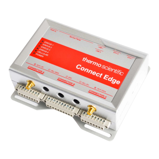
Page 43: Hardware Features
Hardware Features Gateway Interfaces Figure 1 Gateway Front Side Interfaces Ref # Description Supported Models 1 Antenna connector for 2.4 GHz Wi-Fi All except EDGEPTGATE01 All except EDGEPTGATE01, 2 Main antenna connector for Internal Cellular Modem EDGEPTGATE02 3 Antenna Connector for Internal GPS None Diversity antenna connector for Internal Cellular All except EDGEPTGATE01,... -
Page 44: Gateway Features
Ref # Description 1 USB 2 Connector Figure 3 - Gateway Left Side Interface Ref # Description 1 Micro SIM Top card receptacle (pull-lever) 2 DIP-switch (Not used) 3 Restore button 4 Hardware reset button 5 RTC backup supercap (not removable) 6 Micro SIM Bottom card receptacle (push-pull) Figure 4 - Gateway Service Features (located behind Service Panel depicted in Figure 2) Gateway Features... -
Page 45: Gateway Led Indicators
Gateway LED Indicators Ref# Use Color Status Status 1 Green LED Blinking: Gateway bootup and preparing the gateway software LED Solid: Gateway is ready Status 2 Green Not used Status 3 Amber LED Blinking: Attempting to connect to cloud LED Solid: Connected to the cloud Status 4 Amber LED Blinking after a bootup indicates a failure during the bootup or software starting process... -
Page 46: Adapter Features
Adapter Features Figure 5 - Adapter Features Ref # Description Function 1 Hardware reset button Press triggers an adapter reboot 2 Center button Currently not used 3 RGB LED Indicates status Adapter LED Indicators RGB LED: Operating Mode (After a successful configuration) Frequency Status White... -
Page 47: Device Adapter Wiring
2 Hz Configuration failed. This state is entered whenever the adapter is unable to save a new configuration via USB. The adapter will remain in this state until the adapter is reset or power cycled. Green 2 Hz Configuration accepted. This state is entered whenever the adapter successfully saves a new configuration via USB. -
Page 48: Thermo Fisher Connect Overview
Thermo Fisher Connect Overview Thermo Fisher Connect is the universal platform for connected lab equipment. You can access your device data either on the web or through the InstrumentConnect mobile application, available for both iOS and Android devices. Access Device Data Log into your Thermo Fisher Connect account at www.thermofisher.com/edgelogin. - Page 49 2. This will bring you to your dashboard. From this dashboard you are able to see all devices connected to your Thermo Connect account. Right click the menu drop-down on the device you wish to manage the users on and select Manage Users. 3.
-
Page 50: Monitors
Monitors-Sensors allows you to create these alert/alarm rules for active monitoring on the following device types: - Thermo Scientific™ TSX Ultra-Low Temperature Freezer - Incubators, High Performance Refrigerators and Freezers, and Ultra-Low Temperature Freezers 1. -
Page 51: Viewing Device Data
4.Select Monitor Instrument to access settings you can customize. For the creation of a Monitors rule, the user will be able to configure the following: data sample type you wish to use for the rule raw sensor value or a statistical calculation of the data values (max, min, average or sum) An operator to compare against the threshold of your interest: above, below or equals. -
Page 52: Creating Reports
Event Log: Filterable history of the events, alarms, etc. provided by the unit. Creating Reports Click on the Create Report button located on the screen and then select either Table data CSV or Table data PDF from the drop down. This will generate the report and save it to the users desired folder Select the DataConnect icon located on the left-hand panel of the window. -
Page 53: Opc Ua™ Server Overview
Before being able to utilize OPC-UA, contact your Thermo Fisher sales contact to purchase an OPC UA subscription and register that subscription using the Connect Edge Registration portal at https://www.thermofisher.com/productregistration. Subscriptions are needed for the number of devices to be enabled for OPC UA access, but these devices can be on any gateway. -
Page 54: Setting Pc Static Ip Address
Credentials: Only username/password credentials are supported. By default the Gateway admin account can be used. Service accounts can be created as described in the previous section. For information on the specific node tree parameters refer to the latest OPC UA documentation available in our Resources section at www.thermofisher.com/connectedge/resources Setting PC Static IP Address... - Page 55 8. Input IP properties and save (OK).
-
Page 56: Mac Os
MAC OS 1. Navigate to System Preferences (either from your dock or by clicking the Apple menu at the top of your screen. 2. Select Network 3. Select your Ethernet connection from the left list menu 4. Change the Configure IPv4 to “Manually” 5. -
Page 57: Incubators
Incubators Device Type Applicable Model Event Event Type Description Incubator Alarm EQUIPMENT_DISCONNECTED Equipment disconnected: Connection between Connect Edge and equipment interrupted: check equipment power and equipment data connections. Incubator Alarm DOOR_AJAR Device door open too long Alarm: Device door has been open for longer than 30 seconds. -
Page 58: Ult
Incubator Alarm SENSOR_BREAKAGE_O2 O2 Error: Sensor Breakage: Measured value exceeds accepted limit. Incubator Alarm HIGH_O2 O2 Actual value above Alarm: O2 Actual Value > Set value + Incubator Alarm LOW_O2 O2 Actual value low Alarm: O2 Actual Value < Set value - 1%. Incubator Alarm COMM_ERROR_O2... - Page 59 Recommend cleaning the filter and condenser. Please contact TSX Series, UxF/HFU- service if you are unable to T/TSU/88000 Series CLNFILTER_ALARM clear notification. Note: When the Applicable Model is “All” that is the list of models of that type supported by Connect Edge.
-
Page 60: Networking Guidance
Networking Guidance Network Requirements Port Openings Required Open Network A (Internet) External Ports 443 (HTTPS, MQTTS) o broker.cg.tfcprod.thermofisher.com o *.iot.us-east-1.amazonaws.com 123 (NTP)* o ntp.pool.org 53 (Domain Name Service) o URL depends on configured DNS servers 1194 (Rapid OpenVPN – Device dependent) o URL is location-dependent *Network Time Protocol (NTP) allows the system clock to be set accurately and is required. - Page 61 NTP DNS DHCP OCP.TCP (optional if OPC UA installed) ETH 1 Can be configured to get IP address from a DHCP server or set an IP manually. Can provide appropriate ports for Instrument services and local UI access. ...
-
Page 62: Network B (Instrument/Service Network)
Desired Signal Level A signal strength < -70 DBM is not recommended and results in a warning on the Gateway Management monitoring page. SSID Name Limitations o None Cellular Supported services are carrier-specific. Provided Settings o APN o Dial String o Auth Type: <carrier specific>... -
Page 63: Network Security Features And Recommendations
Wi-Fi 0 Two modes are available in this option: Access Point mode or Station mode. Access Point Mode The following must be configured: o SSID (default is TF_GW_<last 4 digits of ETH 0 MAC address>) o Wi-Fi Password (default is randomly assigned) o Static IP o Subnet Mask o Security Standard (WPA2 Highly Recommended) -
Page 64: Supported Network Interfaces And Configuration Options
Supported Network Interfaces and Configuration Options Default Settings The gateway default has the following network configuration options enabled: ETH 1: 10/100 Mbps ETH 0: 10/100 Mbps The gateway default has the following network configuration options disabled: Wi-Fi 0: 2.4 or 5GHz 802.11a ... -
Page 67: Troubleshooting
Troubleshooting Problem Possible Cause Gateway does not boot No power If the blue power LED is not lit, verify that the power supply is properly connected to a live outlet. Reboot failed If the blue power LED is lit, unplug power from gateway, wait 10 seconds, and then plug power back into gateway Gateway Status 1 LED does not go solid... -
Page 68: Maintaining Your Connect Edge Hardware
Adapter mis- Re-connect adapter to a gateway USB port configured to apply configuration settings OPC-UA Software does not install Subscription Purchase a Connect Edge OPC-UA server needed subscription Password is not recognized Extra characters If copying the password from other... -
Page 69: How To Safely Remove The Power Supply
Periodically inspect the product to verify its integrity and to ensure proper operation. To maintain the product, complete the following steps: Carefully read and understand the instructions contained in Safety Considerations. Safely remove the power supply. Verify the installation of the product. ... - Page 70 China +800 810 5118, +400 650 5118 +8621 68654588 France +33 2 2803 2180 +33 2 2803 2180 Germany (international) +49 6184 90 6000 0800 1 536 376 Germany (national toll free) 0800 1 536 376 0800 1 536 376 India toll free 1800 22 8374 +91 22 6716 2200...
Need help?
Do you have a question about the Connect Edge and is the answer not in the manual?
Questions and answers