
Subscribe to Our Youtube Channel
Related Manuals for PerkinElmer Quantum GX2 microCT

Summary of Contents for PerkinElmer Quantum GX2 microCT
- Page 1 S Y S T E M M A N U A L Quantum GX2 microCT Imaging System April 2018 PN CLS141296 Rev C...
- Page 2 Telephone: +1 (800) 762-4000 (US) or +1 (203) 425-4602 Fax: +1 (203) 944-4904 E-mail: global.techsupport@perkinelmer.com Sales: CustomerCareUS@perkinelmer.com Copyright © 2018 PerkinElmer Health Sciences, Inc. and its parent, affiliated, and subsidiary companies. All rights reserved, including but not limited to those rights to reproduce this publication or parts thereof.
-
Page 3: Table Of Contents
About This Manual ........... . . 1 What’s New in the Quantum GX2 microCT Imaging System ....2 Quantum GX2 microCT Help . - Page 4 Quantum GX2 microCT Imaging System Manual Contents Transfer Bed and Mouse Imaging Shuttle ........23 FMT Mouse Imaging Cassette .
- Page 5 Cleaning the Quantum GX2 microCT ........
-
Page 6: Chapter 1 Welcome
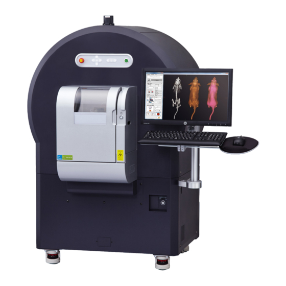
Contact Information on page 4 1.1 About This Manual Welcome to the Quantum GX2 microCT Imaging System Manual. The Quantum GX2 microCT Imaging System is a high-speed CT system used for small animal X-ray imaging. The imaging system is a low-dose X-ray micro-computed tomography scanner. The scanner acquires high-quality slice images which are rendered for 3D visualization. -
Page 7: What's New In The Quantum Gx2 Microct Imaging System
Obtain and view CT images Please read this manual carefully before using the Quantum GX2 microCT Imaging System to obtain safe, optimum performance, and a maximum service life from the imaging system. 1.2 What’s New in the Quantum GX2 microCT Imaging System Table 1.1... -
Page 8: Quantum Gx2 Microct Help
You can view a tooltip about a software button function by putting the mouse cursor over the button. 1.4 Additional Important Documentation Table 1.2 lists other important documentation related to the use of the Quantum GX2 microCT Imaging System. Table 1.2 Documentation for the Quantum GX2 microCT Imaging System... -
Page 9: Contact Information
Quantum GX2 microCT Imaging System Manual Chapter 1 | Welcome 1.5 Contact Information PerkinElmer Health Sciences 940 Winter Street Waltham, Massachusetts 02451 USA www.PerkinElmer.com Technical Support Telephone: +1 (800) 762-4000 (US) or +1 (203) 425-4602 Fax: +1 (203) 944-4904 E-mail: global.techsupport@perkinelmer.com... -
Page 10: Chapter 2 Safety, Warnings, And Radiation Hazards
VOLTAGE! Provides safety information about high voltage or risk of electric shock. Safety Symbols Table 2.1 shows safety symbols that are found on the Quantum GX2 microCT and in this manual. Table 2.1 Safety Symbols Symbol Definition Warning: Hazardous voltage. -
Page 11: Instructions
An X-ray safety survey must be performed when the imaging system is installed or after it has been moved. A survey is also to be performed when the Quantum GX2 microCT has undergone any form of service in which the access panels have been opened, the safety interlocks have been adjusted, or any of the shielding has been removed and re-installed. -
Page 12: Environmental Considerations For The System Components
If you need assistance with this requirement, contact PerkinElmer technical support. For more details and contact information, see Safe Operating and Emergency Procedures for the Operation of the Quantum GX2 microCT Cabinet X-Ray System. This document was provided with the pre-installation instructions. -
Page 13: Cleaning Or Moving The System Components
The Quantum GX2 microCT is configured for the voltage requirements of the installation locality that was specified at the time of order. If the Quantum GX2 microCT is moved to another area, make sure that the same voltage requirements exist. -
Page 14: Servicing
Power Outages If the Quantum GX2 microCT experiences a loss of supply power, turn off the power switch for all components and do not restart the system until reliable power has been restored. -
Page 15: Warnings
Mechanical Safety The Quantum GX2 microCT Imaging System is heavy and weighs approximately 600 kg. The imaging system has many internal motorized components that can move at any time. The X-ray flat panel detector and source located inside of the bore area are delicate parts and should not be handled with bare hands or sprayed with cleaning agents. -
Page 16: Chemical & Biological Safety
Dispose of all waste materials according to appropriate environmental health and safety guidelines. It is your responsibility to decontaminate the Quantum GX2 microCT Imaging System before requesting service by PerkinElmer technical support. Ask your laboratory safety officer to advise you about the level of containment required for your application and about the proper decontamination or sterilization procedures to follow. -
Page 17: Access Panels
PerkinElmer technical service representative. Do not modify the Quantum GX2 microCT Imaging System in ANY manner by making any kind of hole or aperture in the imaging system or removing any component that is part of the radiation shielding. -
Page 18: X-Ray Dose Limits
X-rays could be generated. For reasons discussed in the warning above, it is important not to attempt defeat of any of these safety features. PerkinElmer will perform at least two safety tests on every system at the time of installation: At the time of manufacturing ... -
Page 19: Regulatory Compliance
becomes difficult to open or close. See Surveying the Quantum GX2 microCT for Radiation Leakage on page 80 for more information. Regulatory Compliance Customers in the US are directed to check with their state radiation control program director for registration requirements. -
Page 20: Chapter 3 Quantum Gx2 Microct Imaging System Components
Transfer Bed and Mouse Imaging Shuttle on page 23 FMT Mouse Imaging Cassette on page 24 3.1 Components The Quantum GX2 microCT Imaging System includes scanner with a movable sample holder surrounded by a rotating gantry (Figure 3.1). The gantry has an X-ray source and a flat panel detector mounted on it. - Page 21 Quantum GX2 microCT Imaging System Manual Chapter 3 | Quantum GX2 microCT Imaging System Components Figure 3.2 Quantum GX2 microCT Scanner – Front X-ray ON indicator Tube inlet System front panel Figure 3.4 more details. Safety key switch Figure 3.3 Quantum GX2 microCT Scanner – Rear...
- Page 22 Quantum GX2 microCT Imaging System Manual Chapter 3 | Quantum GX2 microCT Imaging System Components Figure 3.4 Quantum GX2 microCT Imaging System Front Panel Emergency OFF button Power ON/OFF button X-axis stage controls Z-axis stage controls Y-axis stage controls Figure 3.5 Quantum GX2 microCT Imaging System Sample Chamber...
- Page 23 Quantum GX2 microCT Imaging System Manual Chapter 3 | Quantum GX2 microCT Imaging System Components Table 3.1 Standard Accessories Item Photo Mouse bed Rat bed Small bore cover Large bore cover 18mm FOV bore cover and bed No photo available.
-
Page 24: Control Panel
Quantum GX2 microCT Imaging System Manual Chapter 3 | Quantum GX2 microCT Imaging System Components Control Panel The Control Panel appears when the Quantum GX2 microCT software starts (Figure 3.6). See: Page for instructions on starting the software and Control Panel details. -
Page 25: Door Operation
Ray Filters, page 64). 3.2 Door Operation The Quantum GX2 microCT sample chamber door has shielding to prevent the escape of X-ray radiation and should not be tampered with or modified in any way. The door also contains part of the X-ray safety interlock system. -
Page 26: Key Selector Switch Lost Keys
3.5 Scanning System and Acquisition Computer Specifications The computer contains an Intel family processor and Windows ® operating system. The computer controls the Quantum GX2 microCT Imaging System. A printer can be connected to the computer. Scanning System Specifications Scanner Item Description... -
Page 27: Computer Specifications
Installation category 3.7 Tube Inlet The Quantum GX2 microCT Imaging System is equipped with a tube inlet for use with external devices such as the RAS-4 Anesthesia System or angiographic injectors that are inserted into the sample chamber or gantry (Figure 3.8). -
Page 28: Transfer Bed And Mouse Imaging Shuttle
The transfer bed replaces the acrylic beds supplied. A single mounting screw secures the transfer bed to the movable sample platform on the Quantum GX2 microCT Imaging System scanner. The bed has an anesthesia supply and exhaust tube attached that connects to the XGI-8 Gas Anesthesia System... -
Page 29: Fmt Mouse Imaging Cassette
Imaging System and the FMT Imaging System. The cassette enables transport between the imaging systems without disrupting subject position so that 3D volumetric data acquired on the Quantum GX2 microCT can be precisely registered with the optical data. Figure 3.10 FMT Mouse Imaging Cassette and Adapter... -
Page 30: Chapter 4 Getting Started
Workflow Overview Starting the Imaging System 4.1 Workflow Overview Table 4.1 presents an overview of acquiring CT data on the Quantum GX2 microCT Imaging System. Table 4.1 Workflow Overview Step See Page 1. Start the Quantum GX2 microCT Imaging System. -
Page 31: Starting The Imaging System
Chapter 4 | Getting Started 4.2 Starting the Imaging System Turn on the Quantum GX2 microCT Imaging System by pressing the green power button (default user ID – "CTadmin", default password – "ct2admin"). Figure 4.1 Quantum GX2 microCT Imaging System... - Page 32 Quantum GX2 microCT Imaging System Manual Chapter 4 | Getting Started Table 4.2 Control Panel Item Description For More Details, See: Scanner status Figure 6.1 on page 40 Choose a preset or custom scan configuration from this drop- Table 6.2 on page 44 down list.
- Page 33 Quantum GX2 microCT Imaging System Manual Chapter 4 | Getting Started Table 4.2 Control Panel (continued) Item Description For More Details, See: Use the arrows to set the subject orientation. page 47 Initialize – Moves the sample bed to the “0”position and initiates manual control of the sample bed.
-
Page 34: Chapter 5 Working With Databases And Data
Computer\Data (D:)\*. The database facilitates interacting with and managing data sets. To create a database: Open the Database window by starting the Quantum GX2 microCT software (click the icon on the desktop (Figure 5.1). -
Page 35: Connecting To A Database
Quantum GX2 microCT Imaging System Manual Chapter 5 | Working With Databases and Data in the Database window. Alternatively, select File → New Click the New Database button Database on the menu bar. In the dialog box that appears: Enter a name for the new database (Figure 5.2). -
Page 36: Data Organization
Quantum GX2 microCT Imaging System Manual Chapter 5 | Working With Databases and Data 5.3 Data Organization The image data (series) in a database are associated with a study and a sample (Figure 5.4). A sample may include multiple studies and a study may include one or more series. - Page 37 Quantum GX2 microCT Imaging System Manual Chapter 5 | Working With Databases and Data Figure 5.5 Select Database Columns To filter the data: Select a filter from the Name, Study, and/or Series drop-down list (Figure 5.6). Figure 5.6 Database Filters...
-
Page 38: Managing Data
Quantum GX2 microCT Imaging System Manual Chapter 5 | Working With Databases and Data 5.4 Managing Data Reconstructed image data (*.vox) can be imported between databases or exported from the database to another location such as the desktop. Importing Data Select a save location (sample and study) for the data in the Database window. -
Page 39: Moving Data
Quantum GX2 microCT Imaging System Manual Chapter 5 | Working With Databases and Data To export only a subset of the slices contained in an image, choose the “Limited” option and enter a range of slice numbers. Click OK. Moving Data You can move a series to a different sample and study. -
Page 40: Managing Databases
Quantum GX2 microCT Imaging System Manual Chapter 5 | Working With Databases and Data Click Yes in the confirmation message that appears. Figure 5.10 Deleting Data 5.5 Managing Databases Copy a Database Copying a database provides a convenient way to share data. -
Page 41: Search A Database
Quantum GX2 microCT Imaging System Manual Chapter 5 | Working With Databases and Data Search a Database Click the toolbar button. Enter a text string, choose the search options, and click Search. Figure 5.12 Database Search Parameters Delete a Database... -
Page 42: System Administrator Login/Logout
Quantum GX2 microCT Imaging System Manual Chapter 5 | Working With Databases and Data 5.6 System Administrator Login/Logout Select Settings → Login/Logout as Administrator on the menu bar. Enter the administrator password in the dialog box that appears. The default password is ct2admin. -
Page 43: Workstation Setup
Quantum GX2 microCT Imaging System Manual Chapter 5 | Working With Databases and Data Table 5.1 Workstation Requirements for Offline Analyses (continued) Requirement Software Graphics card The following graphics cards are supported: NVidia GeForce GTX 680, 2048MB GDDR5 NVidia GeForce GTX 770, 2GB ... - Page 44 Quantum GX2 microCT Imaging System Manual Chapter 5 | Working With Databases and Data This creates a folder structure on the D: drive that matches the imaging system D: drive (Figure 5.14). Quantum GX Analysis Software only supports subvolume reconstructions using folder hierarchies that match what is on the imaging system workstation.
-
Page 45: Chapter 6 Image Acquisition
Image Acquisition Imaging System Warm-Up Select a Save Location on page 41 Set Up Automatic Image Export on page 43 Set the Scan Conditions on page 43 Place a Subject in the Sample Chamber on page 47 CT Scan Without Gating on page 51 CT Scan With Respiratory Gating on page 52 CT Scan With Cardiac Gating on page 55 Reconstructing a Subvolume or Slice on page 58... -
Page 46: Select A Save Location
Close the imaging system door. NOTE: The Quantum GX2 microCT Imaging System does not generate X-rays unless the door is properly closed and the safety interlock is engaged. There is an audible “click” when the safety interlock properly engages as the door is closed. - Page 47 Quantum GX2 microCT Imaging System Manual Chapter 6 | Image Acquisition Set the Save Location: Connect to a database or create a new database. (See Managing Databases page 9 for details). Follow the instructions in Table 6.1 to select a sample and study for the series.
-
Page 48: Set Up Automatic Image Export
Quantum GX2 microCT Imaging System Manual Chapter 6 | Image Acquisition 6.3 Set Up Automatic Image Export After acquisition, DICOM images can be automatically exported to a user-selected location. Select Setting Automatic → DICOM Export Settings in the Database window. - Page 49 Quantum GX2 microCT Imaging System Manual Chapter 6 | Image Acquisition Table 6.2 Preset Scan Configurations Table 3.2 on page 19 for a description of the scan parameters. Note: FOV 45, 60 and 72 can be used with the small or large bore. FOV 25 and 36 can only be used with the small bore.
-
Page 50: Custom Scan Conditions
Quantum GX2 microCT Imaging System Manual Chapter 6 | Image Acquisition Table 6.2 Preset Scan Configurations (continued) Table 3.2 on page 19 for a description of the scan parameters. Note: FOV 45, 60 and 72 can be used with the small or large bore. FOV 25 and 36 can only be used with the small bore. - Page 51 Quantum GX2 microCT Imaging System Manual Chapter 6 | Image Acquisition Figure 6.6 Setting Custom Scan Conditions Table 4.2 on page 27 for more details on these parameters. Actual current output of the X-ray tube during a scan Actual voltage...
-
Page 52: Place A Subject In The Sample Chamber
Quantum GX2 microCT Imaging System Manual Chapter 6 | Image Acquisition To set scan conditions: Enter a name (under the “Menu Name” column header). Enter values for kV, CT µA, and Live µA. Make a selection from the FOV and Scan Mode drop-down lists. - Page 53 Quantum GX2 microCT Imaging System Manual Chapter 6 | Image Acquisition Figure 6.8 Sample Bed at Out-Limit Position Place the anesthetized subject on the sample bed. If using the Mouse Imaging Shuttle, place the shuttle with the anesthetized subject on the sample bed.
- Page 54 Move the sample bed a specific distance by entering a distance (mm) and click Set (Figure 6.12). Figure 6.11 Quantum GX2 microCT Imaging System Front Panel Emergency OFF button Power ON/OFF button X-axis stage controls Z-axis stage controls...
- Page 55 Quantum GX2 microCT Imaging System Manual Chapter 6 | Image Acquisition Figure 6.12 Control Panel Use these controls to move the sample bed in or out of the bore Gantry position Gantry position at 0 degrees at 90 degrees Check the subject position in the Xcapture window at the 0 degree gantry position: Select "0"...
-
Page 56: Ct Scan Without Gating
Figure 6.14 Control Panel and Xcapture Window During a Scan X-ray tube status = ON Gantry position Remove the subject from the sample chamber after the Quantum GX2 microCT is in Standby mode. CAUTION: Do not remove or change the bore cover until the Quantum GX2 microCT is in standby mode and the CT scan button becomes available. -
Page 57: Ct Scan With Respiratory Gating
Quantum GX2 microCT Imaging System Manual Chapter 6 | Image Acquisition Figure 6.15 AutoViewer If the AutoViewer does not automatically appear, confirm that the AutoView option is selected in the Database window. NOTE: A subvolume or slice(s) of a 3D reconstruction can be reconstructed at higher resolution (smaller pixel size). - Page 58 Quantum GX2 microCT Imaging System Manual Chapter 6 | Image Acquisition Figure 6.16 Xcapture Window Respiratory gating is selected in this example. Image data bounding box Image data outside the bounding box are not used in the reconstruction. ROI positioned over the diaphragm...
- Page 59 Quantum GX2 microCT Imaging System Manual Chapter 6 | Image Acquisition Review the raw data in the GetSynchronizedRaw window (Figure 6.19). To magnify the view, choose the Zoom option an use the left mouse button. The goal is to obtain green squares with Y-axis values that are as uniform as possible.
-
Page 60: Ct Scan With Cardiac Gating
Quantum GX2 microCT Imaging System Manual Chapter 6 | Image Acquisition Table 6.3 Gating Parameters Parameter Gating Type Description Threshold Respiratory The threshold applied to the entire waveform to separate the baseline from the peaks. This allows for an initial separation of the relaxed state of the diaphragm (baseline) from the inspiration/expiration phases of diaphragm motion (peak). - Page 61 Quantum GX2 microCT Imaging System Manual Chapter 6 | Image Acquisition Figure 6.20 Xcapture Window Image data bounding box Image data outside the bounding box are not used in the reconstruction. Position the ROI over the apex of the heart...
- Page 62 Quantum GX2 microCT Imaging System Manual Chapter 6 | Image Acquisition Click Yes in the confirmation message that appears (Figure 6.13). X-rays are energized as indicated by the blinking voltage icon and the imaging system status box (Figure 6.14). The Xcapture window opens, then gantry rotation and image acquisition begin.
-
Page 63: Reconstructing A Subvolume Or Slice
Quantum GX2 microCT Imaging System Manual Chapter 6 | Image Acquisition If you want to filter the data: Click Adjust (Figure 6.24). Enter new values for Lower Breath (%) and/or Cardiac Cutoff Frequency (Hz) in the dialog box that appears and click OK. See Table 6.3 on page 55... - Page 64 Quantum GX2 microCT Imaging System Manual Chapter 6 | Image Acquisition Figure 6.25 Selecting Image Data for Reconstruction Drag the ROI to move it Drag a corner to resize the ROI Figure 6.26 Reconstructed Subvolume ROI outlines the Reconstructed subvolume...
-
Page 65: Slice(S) Reconstruction
Quantum GX2 microCT Imaging System Manual Chapter 6 | Image Acquisition Slice(s) Reconstruction NOTE: If you will be performing slice reconstruction offline, ensure that the workstation meets the requirements in Table 5.1 on page 37. Set up and copy image data to the workstation following... - Page 66 Quantum GX2 microCT Imaging System Manual Chapter 6 | Image Acquisition Click the button. An ROI appears on the image (Figure 6.32). ROI size and position can be adjusted to select a portion of the slice for reconstruction. Figure 6.29 ROI on Image...
-
Page 67: Acquisition In Fluoroscopy Mode
Quantum GX2 microCT Imaging System Manual Chapter 6 | Image Acquisition 6.10 Acquisition in Fluoroscopy Mode In fluoroscopy mode, a range of user-selected frames can be viewed as a movie (scrolling through 2D images) and stored in the image database. -
Page 68: Ring Reduction
Quantum GX2 microCT Imaging System Manual Chapter 6 | Image Acquisition 6.11 Ring Reduction The ring reduction algorithm helps reduce image artifacts and is turned on by default. Figure 6.32 shows example images of before and after ring reduction. Figure 6.32 Images With Example Ring Artifacts... -
Page 69: Imaging With Different X-Ray Filters
Remove the check mark next to the scan technique that was used during acquisition and click OK. Figure 6.34 Turning Off Ring Reduction 6.12 Imaging With Different X-Ray Filters The Quantum GX2 microCT comes with five changeable X-ray filters which allow you to optimize imaging protocols. To change the X-ray filter: Select the filter from the control panel. -
Page 70: Chapter 7 Viewing Images
Viewing Images Previewing Data AutoViewer on page 66 Viewer and SimpleViewer on page 68 Viewing a Z-Axis Slice on page 71 7.1 Previewing Data The Database window provides previews of 3D reconstructions. Table 7.1 Previewing Data in the Database Window Select: To Preview: Sample... -
Page 71: Autoviewer
Quantum GX2 microCT Imaging System Manual Chapter 7 | Viewing Images View the data using one of the CT viewers (Table 7.2). Table 7.2 CT Viewers Viewer Name Description Page AutoViewer The AutoViewer automatically appears after a scan and 3D reconstruction Below are completed. - Page 72 Quantum GX2 microCT Imaging System Manual Chapter 7 | Viewing Images Table 7.3 AutoViewer Menu Commands Menu Command Description File → Import Opens a dialog box that enables you to select another .vox file for viewing. File → Print Opens a dialog box that enables you to print the current AutoViewer display.
-
Page 73: Viewer And Simpleviewer
Quantum GX2 microCT Imaging System Manual Chapter 7 | Viewing Images 7.3 Viewer and SimpleViewer The Viewer provides tools for 2D image display and analysis. NOTE: If you will be viewing 2D images offline, ensure that the workstation meets the requirements in Table 5.1 on page... - Page 74 Quantum GX2 microCT Imaging System Manual Chapter 7 | Viewing Images Table 7.4 Viewer Window (continued) Item Description Image Control Magnifies a selected area of the slice image. Right-click to select a different magnification (2x, 5x, or 10x). Alternatively, click the button the to change magnification.
- Page 75 Quantum GX2 microCT Imaging System Manual Chapter 7 | Viewing Images Table 7.4 Viewer Window (continued) Item Description Reconstruction Places an ROI on an image that will be used to select the image data for reconstruction. Options Places an ROI on an image that will be used to select the image data for reconstruction Pixel Size –...
-
Page 76: Viewing A Z-Axis Slice
Quantum GX2 microCT Imaging System Manual Chapter 7 | Viewing Images Viewing a Z-Axis Slice Click the button in the Viewer Choose viewing options in the dialog box that appears and click OK (Figure 7.4). Thickness – 2, 4, 8, 12, or 16 slices ... -
Page 77: Viewer
Quantum GX2 microCT Imaging System Manual Chapter 7 | Viewing Images 7.4 3D Viewer The 3D Viewer provides tools for rendering 3D reconstructions (classifying the image data and visualization) and viewing the 3D reconstruction from different perspectives. The volume rendering controls provide a histogram-based method for classifying the 3D reconstruction. - Page 78 Quantum GX2 microCT Imaging System Manual Chapter 7 | Viewing Images Table 7.5 Volume Rendering Controls Item Description Preset Rendering Selection Allows you to define components using a monochromatic color table. Segment Mode Preset Rendering Selection Choose from a selection of preset color tables.
- Page 79 Quantum GX2 microCT Imaging System Manual Chapter 7 | Viewing Images Table 7.5 Volume Rendering Controls (continued) Item Description Click an arrow to rotate the 3D reconstruction about the z-axis. To freely rotate about the Z-axis: 1. Click the arrow, then click an image.
- Page 80 Quantum GX2 microCT Imaging System Manual Chapter 7 | Viewing Images Table 7.5 Volume Rendering Controls (continued) Item Description Hides all voxels that are above the intersection of the x and y-axes (the axis coming out of the monitor). Adds/removes voxels to the display after it has been cut using the , or button.
-
Page 81: Classifying Image Data Using The 3D Viewer
Quantum GX2 microCT Imaging System Manual Chapter 7 | Viewing Images Classifying Image Data Using the 3D Viewer The 3DViewer initially displays image data with a default air-noise boundary that identifies bone. Use the volume rendering controls to create and visualize additional intensity ranges or “parts”, for example, a particular type of soft tissue. -
Page 82: Managing Classified Data
Quantum GX2 microCT Imaging System Manual Chapter 7 | Viewing Images Modify the partition to visualize the tissue of interest using the tools partition tools (Table 7.6). To use a tool: Click the button, then click the histogram. Press and hold the mouse button while dragging the mouse left/right or up/down Table 7.6 Partition Tools... - Page 83 Quantum GX2 microCT Imaging System Manual Chapter 7 | Viewing Images Figure 7.11 Selecting a Color Table To edit a part name: Double-click the part name and select Rename on the shortcut menu. Enter a name in the dialog box that appears. Click OK.
- Page 84 Quantum GX2 microCT Imaging System Manual Chapter 7 | Viewing Images 3DViewer Display Options You can adjust the detail level and shading that is used to render the 3D reconstruction in the 3DViewer. Click the button to access the tools for setting shading and detail level.
-
Page 85: Chapter 8 Care And Maintenance
Cleaning the Quantum GX2 microCT on page 81 8.1 Surveying the Quantum GX2 microCT for Radiation Leakage PerkinElmer recommends, and some local government agencies may require, an X-ray leakage safety test be performed under the following conditions: Every 12 months ... -
Page 86: Monthly Safety Checks
Clidox-s Disinfectant Pharmacal Research Laboratories, Inc. NOTE: PerkinElmer makes no claims as to the sterility of the Quantum GX2 microCT imaging chamber after using the solutions in Table 8.1. Please refer to the manufacturer’s literature for information as to the applicability of the compound for the organism of interest. - Page 87 Rinse surfaces using a wipe saturated with sterile deionized water. Do not allow puddles of water to remain on the surfaces. Consider dedicating a Quantum GX2 microCT for immunodeficient animals to remove the risk of cross-contamination.
-
Page 88: Chapter 9 Legal Notices
Disclaimers on page 85 9.1 Introduction This manual is provided to you by PerkinElmer Health Sciences, Inc. ("PEHS") on behalf of itself and its affiliates, including but not limited to, Caliper Life Sciences, Inc. ("Caliper"). PEHS and Caliper are referred to collectively throughout this manual as "PerkinElmer". -
Page 89: Trademarks
Quantum GX2 microCT Imaging System Manual Chapter 9 | Legal Notices PerkinElmer warrants for a period of ninety (90) days that such software will conform to PerkinElmer's or the Software manufacturer's program manuals current at the time of shipment to Customer when properly installed; provided, however, that PerkinElmer does not warrant that the operation of the software will be uninterrupted or error-free. -
Page 90: Disclaimers
Any changes or modifications of the System, not expressly approved by PerkinElmer, will void the Limited Warranty and any repair thereafter shall be charged to the Customer. Any movement of the System not performed by authorized personnel of PerkinElmer may void the Limited Warranty. -
Page 91: Appendix A Troubleshooting
Appendix A Troubleshooting Issue Possible Cause Corrective Action Cannot turn on the CT Emergency Stop button has Release the Emergency Stop button. scanner been pressed. Key switch is in the OFF Turn the key switch to the ON position (turn to position (left position). -
Page 92: Appendix B User-Replaceable Parts
Appendix B User-Replaceable Parts Item Part No. Bore Cover Large, GX CLS143641 Bore Cover Small CLS134993 Bed Large CLS134994 Bed Small CLS134995 Transfer Bed (for use with Mouse Imaging Shuttle) 127167 Adapter (for use with FMT Mouse Imaging Cassette) CLS136435... -
Page 93: Appendix C System Shutdown
Appendix C System Shutdown PerkinElmer does not recommend power cycling the Quantum GX2 micro CT (turning the system components on and off). If it is necessary to shut down the scanner for any reason, it is important to follow the procedure below. -
Page 94: Index
MIP (z-axis) connect Mouse Imaging Shuttle copy move data create – customized view delete offline analysis filtering data workstation requirements organization workstation setup save location – other equipment search delete PerkinElmer contact information data power cord delete database power line surges... - Page 95 Quantum GX2 microCT Imaging System Manual Index power outages power overloading Viewer – power sources viewing data preview data – 3D Viewer – AutoViewer – Viewer – radiation voltage safety symbol effects estimated dose hazards – warm-up – survey for leakage...
Need help?
Do you have a question about the Quantum GX2 microCT and is the answer not in the manual?
Questions and answers