ABB ACH480 Hardware Manual
Drives for hvac
Hide thumbs
Also See for ACH480:
- Hardware manual (214 pages) ,
- User manual (18 pages) ,
- Quick installation and start-up manual (6 pages)
Table of Contents
Advertisement
Quick Links
Advertisement
Table of Contents

Related Manuals for ABB ACH480


Summary of Contents for ABB ACH480
- Page 1 — ABB DRIVES FOR HVAC ACH480 drives Hardware manual...
- Page 3 ACH480 drives Hardware manual Table of contents 1. Safety instructions 4. Mechanical installation 6. Electrical installation – IEC 7. Electrical installation – North America 3AXD50000245949 Rev D Original instructions EFFECTIVE: 2024-05-20...
-
Page 5: Table Of Contents
Table of contents 5 Table of contents 1 Safety instructions Contents of this chapter ..................Use of warnings and notes ..................General safety in installation, start-up and maintenance ........ Electrical safety in installation, start-up and maintenance ......Electrical safety precautions ................Additional instructions and notes .............. - Page 6 6 Table of contents Software information label ................Type designation key ....................Basic code ......................Option codes ...................... 4 Mechanical installation Contents of this chapter ..................Installation alternatives ..................Examining the installation site ................Required tools ......................Unpacking the delivery .................... Installing the drive ....................
- Page 7 Table of contents 7 General guidelines – North America .............. Continuous motor cable shield/conduit and metal enclosure for equipment on the motor cable ............... Separate control cable ducts ................Implementing short-circuit and thermal overload protection ......Protecting the drive and input power cable in short-circuits ....Protecting the motor and motor cable in short-circuits ......
- Page 8 8 Table of contents Additional information on the control connections ........Embedded EIA-485 fieldbus connection .......... PNP configuration for digital inputs ..........NPN configuration for digital inputs ..........Connection for obtaining 0 … 10 V from analog output 2 (AO2) . Connection examples of two-wire and three-wire sensors ..
- Page 9 Table of contents 9 NPN configuration for digital inputs ..........Connection for obtaining 0 … 10 V from analog output 2 (AO2) . Connection examples of two-wire and three-wire sensors ..AI and AO (or AI, DI and +10 V) as PTC motor temperature sensor interface ....................
- Page 10 10 Table of contents Fuses ........................... IEC fuses ......................gG fuses (IEC) ..................gR fuses (IEC) ..................UL (NEC) fuses ....................UL (NEC) fuse alternatives ..............Alternative short-circuit protection ..............Miniature circuit breakers (IEC) ..............Miniature circuit breakers (UL) ..............Manual self-protected combination motor controller –...
- Page 11 Table of contents 11 Category C3 ......................Category C4 ......................UL checklist ........................ Disclaimers ........................ Generic disclaimer .................... Cyber security disclaimer ................Declarations of conformity ..................11 Dimension drawings Contents of this chapter ..................Frame R0 ........................Frame R0 (front & side) - IP20 / UL open type ..........Frame R0 (bottom &...
- Page 12 Compliance with the European Machinery Directive and the UK Supply of Machinery (Safety) Regulations ..............Wiring .......................... Connection principle ..................Single ACH480 drive, internal power supply ........Single ACH480 drive, external power supply ........Wiring examples ....................Single ACH480 drive, internal power supply ........
- Page 13 Table of contents 13 Grounding of protective shields ..............Operation principle ....................Start-up including validation test ................. Competence ....................... Validation test reports ..................Validation test procedure ................Use ..........................Maintenance ......................Competence ....................... Fault tracing ......................Safety data ......................... Terms and abbreviations ................. TÜV certificate ....................
- Page 14 14 Table of contents Electrical installation ....................Start-up ........................Configuration parameters ..................Technical data ......................Further information...
-
Page 15: Safety Instructions
Safety instructions 15 Safety instructions Contents of this chapter This chapter contains the safety instructions which you must obey when you install, start-up, operate and do maintenance work on the drive. If you ignore the safety instructions, injury, death or damage can occur. Use of warnings and notes Warnings tell you about conditions which can cause injury or death, or damage to the equipment. -
Page 16: General Safety In Installation, Start-Up And Maintenance
16 Safety instructions General safety in installation, start-up and maintenance These instructions are for all personnel who do work on the drive. WARNING! Obey these instructions. If you ignore them, injury or death, or damage to the equipment can occur. •... - Page 17 Safety instructions 17 Note: • If you select an external source for the start command and it is on, the drive will start immediately after fault reset unless you configure the drive for pulse start. See the firmware manual. • Only authorized persons are allowed to repair a malfunctioning drive.
-
Page 18: Electrical Safety In Installation, Start-Up And Maintenance
18 Safety instructions Electrical safety in installation, start-up and maintenance ■ Electrical safety precautions These electrical safety precautions are for all personnel who do work on the drive, motor cable or motor. WARNING! Obey these instructions. If you ignore them, injury or death, or damage to the equipment can occur. -
Page 19: Additional Instructions And Notes
Safety instructions 19 Note: If cables are not connected to the drive DC terminals, measuring the voltage from the DC terminal screws can give incorrect results. 6. Install temporary grounding as required by the local regulations. 7. Ask for a permit to work from the person in control of the electrical installation work. -
Page 20: Grounding
20 Safety instructions ■ Grounding These instructions are for all personnel who are responsible for the grounding of the drive. WARNING! Obey these instructions. If you ignore them, injury or death, or equipment malfunction can occur, and electromagnetic interference can increase. If you are not a qualified electrical professional, do not do grounding work. -
Page 21: General Safety In Operation
Safety instructions 21 General safety in operation These instructions are for all personnel that operate the drive. WARNING! Obey these instructions. If you ignore them, injury or death, or damage to the equipment can occur. • If you have a cardiac pacemaker or other electronic medical device, keep away from the area near motor, drive, and the drive power cabling when the drive is in operation. -
Page 22: Safety In Operation
22 Safety instructions • Do not do work on the drive when a rotating permanent magnet motor is connected to it. A rotating permanent magnet motor energizes the drive including its input and output power terminals. Before installation, start-up and maintenance work on the drive: •... -
Page 23: Introduction To The Manual
The chapter contains a list of related manuals and a flowchart for installation and commissioning. Applicability This manual is applicable to ACH480 drives. Target audience This manual is intended for people who plan the installation, install, commission and do maintenance work on the drive, or create instructions for the end user of the drive concerning the installation and maintenance of the drive. -
Page 24: Quick Installation And Commissioning Flowchart
24 Introduction to the manual Quick installation and commissioning flowchart Task Identify the frame size: R0, R1, R2, etc. Type designation key (page 36) Plan the installation. Guidelines for planning the electrical installa- tion (page 45) Check the ambient conditions, ratings and required cooling air flow. - Page 25 Introduction to the manual 25 Task Refer to ACH480 drives quick installation and Commission the drive. start-up guide (3AXD50000247141 [English]) ACH480 HVAC control program firmware manual (3AXD50000247134 [English]).
-
Page 26: Terms And Abbreviations
26 Introduction to the manual Terms and abbreviations Term Description ACH-AP-H Assistant control panel with Hand-Off-Auto functionality ACH-AP-W Assistant control panel with Hand-Off-Auto functionality and Bluetooth interface BAPO Optional auxiliary power extension module BCBL-01 Optional USB to RJ45 cable BIO-01 Optional I/O extension module. -
Page 27: Related Manuals
I/O & EIA-485 module Safety integrity level (1…3) (IEC 61508, IEC 62061, IEC 61800-5-2) Safe torque off (IEC/EN 61800-5-2) Related manuals You can find manuals on the Internet. See below for the relevant code/link. For more documentation, go to www.abb.com/drives/documents. ACH480 manuals... -
Page 29: Operation Principle And Hardware Description
This chapter briefly describes the operation principle and construction of the drive. Operation principle The ACH480 is a drive for controlling asynchronous AC induction motors, permanent magnet synchronous motors and ABB synchronous reluctance motors (SynRM motors). The drive is optimized for cabinet installation. -
Page 30: Simplified Main Circuit Diagram
■ IEC and UL (NEC) product types The ACH480 series consists of IEC product types and UL (NEC) product types. The IEC types are designed for global use. The UL (NEC) types are specifically designed for use in North America. -
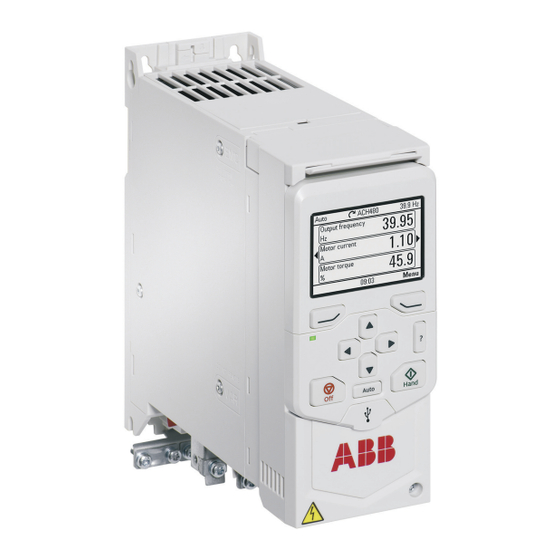
Page 31: Layout
Operation principle and hardware description 31 Layout Type designation label Motor and brake resistor terminals Model information label Cooling fan (on frames R1…R4) Firmware information label Front cover Control panel connection Control terminals Control panel Cold configuration adapter connection (CCA-01) EMC filter grounding screw Front option slot Varistor grounding screw... -
Page 32: Control Connections
32 Operation principle and hardware description Control connections There are fixed control connections on the base unit and additional control connections on the installed option module. ■ Standard unit (with RIIO-01) Connections of the base unit: 1. Auxiliary voltage output 2. -
Page 33: Base Unit
Operation principle and hardware description 33 ■ Base unit Connections of the base unit: 1. Auxiliary voltage output 2. Digital inputs 3. Safe torque-off connections 4. Relay output connection 5. Cold configuration adapter connection for CCA-01 6. Front option module slot 1 +24V DGND RO1C... -
Page 34: Control Panel Options
Frame size Option code Installation instructions 3AXD50000187034 UL Type 1 kit for ACS380, ACS480 and 3AXD50000176779 ACH480 installation guide, frames R0 to R2 (3AXD50000235254) 3AXD50000178780 3AXD50000179220 UL Type 1 kit for ACS380, ACS480 and ACH480 installation guide, frames R3 to R4... -
Page 35: Drive Labels
Operation principle and hardware description 35 Drive labels The drive has these labels: • type designation label on the left side of the drive • model information label on the top of the drive • software information label under the control panel. Example labels are shown in this section. -
Page 36: Software Information Label
Serial number and drive software version Type designation key The type designation key shows the specifications and the configuration of the drive. ■ Basic code Type code example: ACH480-04-12A7-4 Code Description ACH480 Product series Construction. 04 = Module When no options are selected: cabinet optimized module, IP20 (UL open type), ACH-AP-H assistant control panel, RIIO-01 I/O &... - Page 37 Operation principle and hardware description 37 Code Description K451 FDNA-01 DeviceNet™ adapter module K454 FPBA-01 PROFIBUS DP adapter module K457 FCAN-01 CANopen adapter module K458 FSCA-01 RS-485 (Modbus/RTU) adapter module K465 FBIP-01 BACnet/IP adapter module, 2-port K469 FECA-01 EtherCat adapter module K470 FEPL-02 EtherPOWERLINK adapter module FENA-21 Ethernet adapter module for EtherNet/IP™, Modbus TCP and PROFINET...
- Page 38 38 Operation principle and hardware description Code Description R708 Printed manuals in Spanish R709 Printed manuals in Portuguese R711 Printed manuals in Russian R712 Printed manuals in Chinese R713 Printed manuals in Polish R714 Printed manuals in Turkish 1) Manuals in English may be included if a translation in the specified language is not available.
-
Page 39: Mechanical Installation
Mechanical installation 39 Mechanical installation Contents of this chapter This chapter tells how to examine the installation site, unpack and examine the delivery and install the drive mechanically. Installation alternatives You can install the drive: • with screws on to a wall •... -
Page 40: Examining The Installation Site
40 Mechanical installation • You can install frames R1, R2, R3 and R4 tilted to a maximum of 90 degrees, from vertical to fully horizontal orientation. • Do not install the drive upside down. • Make sure that the hot exhaust air from a drive does not flow into the cooling inlet of other drives or equipment. -
Page 41: Unpacking The Delivery
Mechanical installation 41 Unpacking the delivery Keep the drive in its package until you are ready to install it. After unpacking, protect the drive from dust, debris and moisture. Make sure that these items are included: • drive • options, if ordered with an option code •... -
Page 42: To Install The Drive To A Din Installation Rail
42 Mechanical installation 4. Install the mounting screws into the holes. Leave a gap between the screw head and installation surface. 5. Put the drive onto the mounting screws. 6. Tighten the mounting screws. ■ To install the drive to a DIN installation rail Use an IEC/EN 60715 top hat type installation rail, width ×... - Page 43 Mechanical installation 43 2. Push and hold the locking button down. 3. Put the top tabs of the drive onto the top edge of the DIN installation rail. 4. Put the drive against the bottom edge of the DIN installation rail. 5.
-
Page 45: Guidelines For Planning The Electrical Installation
ABB does not assume any liability whatsoever for any installation which breaches the local laws and/or other regulations. Furthermore, if the recommendations given by ABB are not followed, the drive may experience problems that the warranty does not cover. -
Page 46: Selecting The Main Contactor
Checking the compatibility of the motor and drive Use asynchronous AC induction motor, permanent magnet synchronous motor or ABB synchronous reluctance motor (SynRM motors) with the drive. Multiple induction motors can be connected to the drive at a time when using the scalar motor control mode. -
Page 47: Selecting The Power Cables
Guidelines for planning the electrical installation 47 Selecting the power cables ■ General guidelines Select the input power and motor cables according to local regulations. • Current: Select a cable capable of carrying the maximum load current and suitable for the prospective short-circuit current provided by the supply network. -
Page 48: Power Cable Types
48 Guidelines for planning the electrical installation ■ Power cable types Preferred power cable types This section shows the preferred cable types. Make sure that the selected cable type also complies with local/state/country electrical codes. Cable type Use as input power cabling Use as motor cabling and as brake resistor cabling Symmetrical shielded (or ar-... -
Page 49: Alternate Power Cable Types
Guidelines for planning the electrical installation 49 Alternate power cable types Cable type Use as input power cabling Use as motor cabling and as brake resistor cabling Yes with phase conductor Yes with phase conductor smaller than 10 mm 2 (8 AWG) smaller than 10 mm 2 (8 AWG) Cu, or motors up to 30 kW (40 hp). -
Page 50: Not Allowed Power Cable Types
■ Additional guidelines – North America ABB recommends the use of metallic conduit for power wiring. ABB also recommends the use of symmetrical shielded VFD cable between drive and motor(s). This table shows examples of methods for wiring the drive. Refer to NFPA 70 (NEC) along with state and local codes for the appropriate methods for your application. -
Page 51: Metal Conduit
Guidelines for planning the electrical installation 51 Wiring method Notes Free air Prefer symmetrical shielded VFD cable. Enclosures, air handlers, etc. Allowed internally in enclosures when in ac- cordance with UL. 1) Metallic conduit may be used as an additional ground path, provided this path is a solid path capable of handling ground currents. -
Page 52: Grounding Requirements
52 Guidelines for planning the electrical installation Insulation jacket Helix of copper tape or copper wire Copper wire shield Inner insulation Cable core Grounding requirements This section gives general requirements for grounding the drive. When you plan the grounding of the drive, obey all the applicable national and local regulations. The conductivity of the protective earth conductor(s) must be sufficient. -
Page 53: Additional Grounding Requirements - Iec
Guidelines for planning the electrical installation 53 earth conductor must be determined in a manner which produces a conductance equivalent to that which results from the application of this table. Cross-sectional area of the phase conduct- Minimum cross-sectional area of the corres- ponding protective earth conductor S (mm 2 ) S p (mm 2 ) -
Page 54: Additional Grounding Requirements - Ul (Nec)
Shielding Only use shielded control cables. Use a double-shielded twisted pair cable for analog signals. ABB recommends this type of cable also for the pulse encoder signals. Use one individually shielded pair for each signal. Do not use common return for different analog signals. -
Page 55: Relay Cable
■ Relay cable The cable type with braided metallic shield (for example ÖLFLEX by LAPPKABEL, Germany) has been tested and approved by ABB. ■ Control panel to drive cable Use EIA-485, Cat 5e (or better) cable with male RJ-45 connectors. The maximum length of the cable is 100 m (328 ft). -
Page 56: General Guidelines - North America
56 Guidelines for planning the electrical installation min. 300 mm (12 in) min. 300 mm (12 in) min. 500 mm (20 in) 90° min. 200 mm (8 in) min. 500 mm (20 in) Motor cable Input power cable Control cable Brake resistor or chopper cable (if any) ■... -
Page 57: Continuous Motor Cable Shield/Conduit And Metal Enclosure For Equipment On The Motor Cable
Guidelines for planning the electrical installation 57 Input power cabling Motor cabling Conduit ■ Continuous motor cable shield/conduit and metal enclosure for equipment on the motor cable To minimize the emission level when safety switches, contactors, connection boxes or similar equipment are installed on the motor cable between the drive and the motor: •... -
Page 58: Separate Control Cable Ducts
58 Guidelines for planning the electrical installation ■ Separate control cable ducts Put 24 V DC and 230 V AC (120 V AC) control cables in separate ducts, unless the 24 V DC cable is insulated for 230 V AC (120 V AC) or insulated with an insulation sleeving for 230 V AC (120 V AC). -
Page 59: Protecting The Drive, And The Input Power And Motor Cables Against Thermal Overload
Guidelines for planning the electrical installation 59 ■ Protecting the drive, and the input power and motor cables against thermal overload If the cables have the correct size for the nominal current, the drive protects itself and the input and motor cables against thermal overload. No additional thermal protection devices are needed. -
Page 60: Implementing A Motor Temperature Sensor Connection
60 Guidelines for planning the electrical installation Implementing a motor temperature sensor connection WARNING! IEC 61800-5-1 requires double or reinforced insulation between live parts and accessible parts when: • the accessible parts are not conductive, or • the accessible parts are conductive, but not connected to the protective earth. -
Page 61: Implementing The Safe Torque Off Function
227). Using a safety switch between the drive and the motor ABB recommends to install a safety switch between the permanent magnet motor and the drive output. The switch is needed to isolate the motor from the drive during maintenance work on the drive. - Page 62 62 Guidelines for planning the electrical installation inductively to other conductors in the control cable and form a risk of malfunction in other parts of the system. Install the protective component as close to the inductive load as possible. Do not install protective components at the relay outputs.
-
Page 63: Electrical Installation - Iec
Electrical installation – IEC 63 Electrical installation – IEC Contents of this chapter This chapter describes how to: • measure the insulation • do the grounding system compatibility check • change the EMC filter or ground-to-phase varistor connection • connect the power and control cables •... -
Page 64: Measuring The Insulation Resistance - Iec
Use a measuring voltage of 1000 V DC. The insulation resistance of an ABB motor must be more than 100 Mohm (reference value at 25 °C [77 °F]). For the insulation resistance of other motors, refer to the manufacturer’s instructions. -
Page 65: Measuring The Insulation Resistance Of The Brake Resistor Circuit
Electrical installation – IEC 65 ■ Measuring the insulation resistance of the brake resistor circuit WARNING! Obey the safety instructions of the drive. If you ignore them, injury or death, or damage to the equipment can occur. If you are not a qualified electrical professional, do not do installation, commissioning or maintenance work. -
Page 66: Ground-To-Phase Varistor
66 Electrical installation – IEC WARNING! Do not install a drive with the internal EMC filter connected to a grounding system that the EMC filter is not compatible with (for example, an IT system). The supply network becomes connected to ground potential through the internal EMC filter capacitors, which can cause danger or damage to the drive. - Page 67 Electrical installation – IEC 67 variant. Before you connect the drive to the input power, examine the screws and do the necessary actions shown in the table. Screw Screw material When to remove EMC screw or VAR screw label Symmetrically Corner-grounded IT systems (un- grounded TN-S sys-...
-
Page 68: Disconnecting The Emc Filter Or Ground-To-Phase Varistor
68 Electrical installation – IEC ■ Disconnecting the EMC filter or ground-to-phase varistor Before you continue, refer to Compatibility of EMC filter and ground-to-phase varistor with the grounding system (page 66). • To disconnect the EMC filter, remove the metal EMC screw. •... -
Page 69: Guidelines For Installing The Drive To A Tt System
Note: • ABB does not guarantee the EMC performance, because the internal EMC filter is disconnected. • ABB does not guarantee the functioning of the ground leakage detector built inside the drive. - Page 70 70 Electrical installation – IEC The table below shows the line-to-ground voltages in relation to the line-to-line voltage for each grounding system. U L-L U L1-G U L2-G U L3-G Electrical power system type 0.58·X 0.58·X 0.58·X TN-S system (symmetrically grounded) Corner-grounded delta system (nonsym- 1.0·X 1.0·X...
-
Page 71: Connecting The Power Cables - Iec (Shielded Cables)
PE conductor. Motor cable Note: ABB recommends to use a symmetrical shielded cable (VFD cable) as the motor cable. Separate PE cable (motor side). Use a separate grounding cable for the motor side, if the conductivity of the shield is not sufficient, or if there is no symmetrically con- structed PE conductor in the cable. -
Page 72: Connection Procedure
72 Electrical installation – IEC ■ Connection procedure WARNING! Obey the safety instructions of the drive. If you ignore them, injury or death, or damage to the equipment can occur. If you are not a qualified electrical professional, do not do installation, commissioning or maintenance work. Refer to Terminal data for the power cables (page 163) for the tightening torques. - Page 73 Electrical installation – IEC 73 7. Connect the phase conductors of the motor cable to terminals T1/U, T2/V and T3/W. 8. If you use a brake resistor, connect the brake resistor cable to terminals R- and UDC+. Use shielded cable and ground the shield under the grounding clamp for 360-degree grounding.
-
Page 74: Connecting The Control Cables - Iec
74 Electrical installation – IEC Connecting the control cables - IEC Before you connect the control cables, make sure that all option modules are installed. ■ Default I/O connection diagrams (HVAC default) The connection diagrams below are applicable to the standard drive variant with the RIIO-01 I/O &... - Page 75 Electrical installation – IEC 75 Description Connection Terminal Relay outputs +24V Aux. voltage output +24 V DC, max. 250 mA DGND Aux. voltage output common +24 V +24 V DCOM Digital input common for all DGND DGND DCOM DCOM RO1C Common Damper control ×...
-
Page 76: Default Fieldbus Connection Diagram
76 Electrical installation – IEC 4) Drive output frequency: Operation/Parameter Set output frequency through AI1 28.26 Constant frequency 1 28.27 Constant frequency 2 28.28 Constant frequency 3 ■ Default fieldbus connection diagram The connection diagrams are applicable to the base unit with an optional fieldbus adapter module. -
Page 77: Control Cable Connection Procedure
Electrical installation – IEC 77 Connection Description Terminal Fieldbus connection DSUB9 +K457 FCAN-01 CANopen DSUB9 +K454 FPBA-01 Profibus DP RJ45×2 +K465 FBIP-21 BACnet/IP RJ45×2 +K469 FECA-01 EtherCAT RJ45×2 +K475 FENA-21 Ethernet/IP, Profinet, Modbus See the applicable RJ45×2 +K470 FEPL-02 Ethernet Powerlink fieldbus adapter manual. -
Page 78: Additional Information On The Control Connections
78 Electrical installation – IEC 7. Connect the shields and grounding wires to the SCR terminal. Torque the terminal connection to 0.5 … 0.6 N·m (4.4 … 5.3 lbf·in). 8. Mechanically attach the control cables on the outside of the drive. ■... - Page 79 Electrical installation – IEC 79 Connection examples are shown below. With signal ground reference terminal Without signal ground reference terminal 100 ohm Automation controller Drive Termination switch. The devices at the ends of the fieldbus must have termination on. All other devices must have termination off.
-
Page 80: Pnp Configuration For Digital Inputs
80 Electrical installation – IEC PNP configuration for digital inputs Internal and external +24 V power supply connections for PNP (source) configuration are shown in the figures below. Internal +24 V power supply External +24 V power supply (with BAPO-01) +24 V +24 V DGND... -
Page 81: Connection For Obtaining 0
Electrical installation – IEC 81 Connection for obtaining 0 … 10 V from analog output 2 (AO2) To obtain 0 … 10 V from analog output AO2, connect a 500 ohm resistor (or two 1 kohm resistors in parallel) between AO2 and AGND. Examples are shown in the figure below. -
Page 82: Ai And Ao (Or Ai, Di And +10 V) As Ptc Motor Temperature Sensor Interface
82 Electrical installation – IEC AI and AO (or AI, DI and +10 V) as PTC motor temperature sensor interface WARNING! IEC 61800-5-1 requires double or reinforced insulation between live parts and accessible parts when: • the accessible parts are not conductive, or •... - Page 83 Electrical installation – IEC 83 AGND AGND Motor winding Double or reinforced insulation 1…3 PTC sensors Analog input. Set the analog input type to V (volt) in parameter group 12 Standard AI. Define the temperature sensor type, signal source, etc. with parameters 35.11…35.24. For the sensor type, select: PTC analog I/O.
-
Page 84: Ai1 And Ai2 As Pt100, Pt1000, Ni1000, Kty83 And Kty84 Sensor Inputs
84 Electrical installation – IEC +10 V DGND DCOM 1…3 PTC sensors Double or reinforced insulation Motor winding Digital input and analog input. Set the analog input type to V (volt) in parameter group 12 Standard AI. Define the temperature sensor type, signal source, etc. with parameters 35.11…35.24. -
Page 85: Safe Torque Off
Electrical installation – IEC 85 See the firmware manual for information on the related Motor thermal protection function. AGND AGND Motor winding Double or reinforced insulation 1…3 × (Pt100 or Pt1000) or 1 × (Ni1000 or KTY83 or KTY84) Analog input. Set the analog input type to V (volt) in parameter group 12 Standard AI. Define the temperature sensor type, signal source, etc. -
Page 86: Connecting A Pc
86 Electrical installation – IEC To connect an external auxiliary power supply to the drive: Install a BAPO-01 power extension module to the drive. See Installing options (page 86). 2. Connect an external power supply to the +24V and DGND terminals of the base unit. -
Page 87: Installing A Front Option
Electrical installation – IEC 87 • Side option: Multifunction extension module slot on the side of the drive. Refer also to the applicable fieldbus module manual for the installation instructions. For other option modules, refer to: • BREL-01 relay output extension module (page 257) •... -
Page 88: Installing A Side Option
88 Electrical installation – IEC Note: If you have the BIO-01 option module, you can add one additional fieldbus module on top of it. ■ Installing a side option WARNING! Obey the safety instructions of the drive. If you ignore them, injury or death, or damage to the equipment can occur. - Page 89 Electrical installation – IEC 89 6. Attach the grounding bar to the bottom of the side option and to the front ground tab on the drive. Torque the screws to 1 N·m (8.8 lbf·in). 7. Connect the control cables. See the control cable connection instructions.
-
Page 91: Electrical Installation - North America
Electrical installation – North America 91 Electrical installation – North America Contents of this chapter This chapter describes how to: • measure the insulation • do the grounding system compatibility check • change the EMC filter or ground-to-phase varistor connection •... -
Page 92: Measuring The Insulation Resistance - North America
Use a measuring voltage of 1000 V DC. The insulation resistance of an ABB motor must be more than 100 Mohm (reference value at 25 °C [77 °F]). For the insulation resistance of other motors, refer to the manufacturer’s instructions. -
Page 93: Measuring The Insulation Resistance Of The Brake Resistor Circuit
Electrical installation – North America 93 ■ Measuring the insulation resistance of the brake resistor circuit WARNING! Obey the safety instructions of the drive. If you ignore them, injury or death, or damage to the equipment can occur. If you are not a qualified electrical professional, do not do installation, commissioning or maintenance work. -
Page 94: Ground-To-Phase Varistor
94 Electrical installation – North America WARNING! Do not install a drive with the internal EMC filter connected to a grounding system that the EMC filter is not compatible with (for example, an IT system). The supply network becomes connected to ground potential through the internal EMC filter capacitors, which can cause danger or damage to the drive. - Page 95 Electrical installation – North America 95 variant. Before you connect the drive to the input power, examine the screws and do the necessary actions shown in the table. Screw Screw material When to remove EMC screw or VAR screw label Symmetrically Corner-grounded IT systems (un-...
-
Page 96: Disconnecting The Ground-To-Phase Varistor, Or Connecting The Emc Filter
96 Electrical installation – North America ■ Disconnecting the ground-to-phase varistor, or connecting the EMC filter Before you continue, refer to Compatibility of EMC filter and ground-to-phase varistor with the grounding system (page 94). • To disconnect the ground-to-phase varistor, remove the metal VAR screw. •... -
Page 97: Guidelines For Installing The Drive To A Tt System
Note: • ABB does not guarantee the EMC performance, because the internal EMC filter is disconnected. • ABB does not guarantee the functioning of the ground leakage detector built inside the drive. - Page 98 98 Electrical installation – North America The table below shows the line-to-ground voltages in relation to the line-to-line voltage for each grounding system. U L-L U L1-G U L2-G U L3-G Electrical power system type 0.58·X 0.58·X 0.58·X TN-S system (symmetrically grounded) Corner-grounded delta system (nonsym- 1.0·X 1.0·X...
-
Page 99: Connecting The Power Cables - North America (Wiring In Conduits)
■ Connection diagram UDC- UDC+ Drive Drive enclosure Supply disconnecting device and fuses Input power wiring Protective earth (ground) conductor(s) Motor wiring Note: ABB recommends to use a symmetrical shielded cable (VFD cable) as the motor cable. Brake resistor (optional) -
Page 100: Connection Procedure
100 Electrical installation – North America ■ Connection procedure WARNING! Obey the safety instructions of the drive. If you ignore them, injury or death, or damage to the equipment can occur. If you are not a qualified electrical professional, do not do installation, commissioning or maintenance work. Refer to Terminal data for the power cables (page 163) for the tightening torques. - Page 101 Electrical installation – North America 101 8. Connect the phase conductors of the motor wiring to terminals T1/U, T2/V and T3/W. 9. If you use a brake resistor, connect the brake resistor conductors to terminals R- and UDC+. 10. Make sure that the R- and UDC+ terminal screws are tightened. Do this step also if you do not connect cables to the terminals.
-
Page 102: Connecting The Control Cables - North America
102 Electrical installation – North America 13. Connect the other ends of the conductors. Connecting the control cables - North America Before you connect the control cables, make sure that all option modules are installed. ■ Default I/O connection diagrams (HVAC default) The connection diagrams below are applicable to the standard drive variant with the RIIO-01 I/O &... - Page 103 Electrical installation – North America 103 Description Connection Terminal Digital inputs and auxiliary voltage output +24V × Aux. voltage output +24 V DC, max. 250 mA DGND Aux. voltage output common × +24 V +24 V DGND DGND DCOM Digital input common for all ×...
-
Page 104: Default Fieldbus Connection Diagram
104 Electrical installation – North America Description Connection Terminal Safe torque off SGND Safe torque off. Factory connection. Both cir- × SGND cuits must be closed for the drive to start. × × OUT1 OUT1 × Auxiliary voltage input/output +24V Aux. -
Page 105: Control Cable Connection Procedure
Electrical installation – North America 105 Connection Description Terminal Relay outputs +24V Aux. voltage output +24 V DC, max. 250 mA × +24 V DGND Aux. voltage output common × DGND DCOM Digital input common for all × DCOM RO1C Common Damper control ×... -
Page 106: Additional Information On The Control Connections
106 Electrical installation – North America WARNING! Obey the safety instructions of the drive. If you ignore them, injury or death, or damage to the equipment can occur. If you are not a qualified electrical professional, do not do installation, commissioning or maintenance work. Do the steps in section Electrical safety precautions (page 18) before you start... - Page 107 Electrical installation – North America 107 Connect the cable to the EIA-485 terminal on the RIIO-01 I/O module. Obey these wiring instructions: • Attach the cable shields together at each drive, but do not connect them to the drive. • Connect the cable shields only to the grounding terminal in the automation controller.
-
Page 108: Pnp Configuration For Digital Inputs
108 Electrical installation – North America PNP configuration for digital inputs Internal and external +24 V power supply connections for PNP (source) configuration are shown in the figures below. Internal +24 V power supply External +24 V power supply (with BAPO-01) +24 V +24 V DGND... -
Page 109: Connection For Obtaining 0
Electrical installation – North America 109 Connection for obtaining 0 … 10 V from analog output 2 (AO2) To obtain 0 … 10 V from analog output AO2, connect a 500 ohm resistor (or two 1 kohm resistors in parallel) between AO2 and AGND. Examples are shown in the figure below. -
Page 110: Ai And Ao (Or Ai, Di And +10 V) As Ptc Motor Temperature Sensor Interface
110 Electrical installation – North America AI and AO (or AI, DI and +10 V) as PTC motor temperature sensor interface WARNING! IEC 61800-5-1 requires double or reinforced insulation between live parts and accessible parts when: • the accessible parts are not conductive, or •... - Page 111 Electrical installation – North America 111 AGND AGND Motor winding Double or reinforced insulation 1…3 PTC sensors Analog input. Set the analog input type to V (volt) in parameter group 12 Standard AI. Define the temperature sensor type, signal source, etc. with parameters 35.11…35.24. For the sensor type, select: PTC analog I/O.
-
Page 112: Ai1 And Ai2 As Pt100, Pt1000, Ni1000, Kty83 And Kty84 Sensor Inputs
112 Electrical installation – North America +10 V DGND DCOM 1…3 PTC sensors Double or reinforced insulation Motor winding Digital input and analog input. Set the analog input type to V (volt) in parameter group 12 Standard AI. Define the temperature sensor type, signal source, etc. with parameters 35.11…35.24. -
Page 113: Safe Torque Off
Electrical installation – North America 113 See the firmware manual for information on the related Motor thermal protection function. AGND AGND Motor winding Double or reinforced insulation 1…3 × (Pt100 or Pt1000) or 1 × (Ni1000 or KTY83 or KTY84) Analog input. -
Page 114: Connecting A Pc
114 Electrical installation – North America To connect an external auxiliary power supply to the drive: Install a BAPO-01 power extension module to the drive. See Installing options (page 86). 2. Connect an external power supply to the +24V and DGND terminals of the base unit. -
Page 115: Installing A Front Option
Electrical installation – North America 115 • Side option: Multifunction extension module slot on the side of the drive. Refer also to the applicable fieldbus module manual for the installation instructions. For other option modules, refer to: • BREL-01 relay output extension module (page 257) •... -
Page 116: Installing A Side Option
116 Electrical installation – North America Note: If you have the BIO-01 option module, you can add one additional fieldbus module on top of it. ■ Installing a side option WARNING! Obey the safety instructions of the drive. If you ignore them, injury or death, or damage to the equipment can occur. - Page 117 Electrical installation – North America 117 6. Attach the grounding bar to the bottom of the side option and to the front ground tab on the drive. Torque the screws to 1 N·m (8.8 lbf·in). 7. Connect the control cables. See the control cable connection instructions.
-
Page 119: Installation Checklist
Installation checklist 119 Installation checklist Contents of this chapter This chapter contains a checklist for the mechanical and electrical installation of the drive. Checklist Examine the mechanical and electrical installation of the drive before start-up. Go through the checklist together with another person. WARNING! Obey the safety instructions of the drive. - Page 120 120 Installation checklist Make sure that … The insulation resistance of the input power cable, motor cable and motor is meas- ured according to local regulations and the manuals of the drive. The drive is attached securely on an even, vertical and non-flammable wall. The cooling air can flow freely in and out of the drive.
- Page 121 Installation checklist 121 Make sure that … The control cables are connected to the correct terminals, and the terminals are tightened to the correct torque. If a drive bypass connection will be used: The direct-on-line contactor of the motor and the drive output contactor are either mechanically and/or electrically interlocked, that is, they cannot be closed at the same time.
-
Page 123: Maintenance
The chapter contains maintenance intervals and instructions. Maintenance intervals The tables below show the maintenance tasks that can be done by the end user. For the ABB Service offering, contact your local ABB Service representative (www.abb.com/searchchannels). ■ Description of symbols... -
Page 124: Recommended Maintenance Intervals After Start-Up
• The maintenance and component replacement intervals are based on the assumption that the equipment operates within the specified ratings and ambient conditions. ABB recommends annual drive inspections to ensure the highest reliability and optimum performance. • Long-term operation near the specified maximum ratings or ambient conditions may require shorter maintenance intervals for certain components. -
Page 125: Functional Safety Components
The remaining mission time of the whole circuit is however determined by its oldest component. Contact your local ABB service representative for more information. Cleaning the heatsink The drive module heatsink fins pick up dust from the cooling air. The drive runs into overtemperature warnings and faults if the heatsink is not clean. -
Page 126: Replacing The Cooling Fans
Parameter 05.04 Fan on-time counter shows the running time of the cooling fan. After you replace the fan, reset the fan counter. Refer to the firmware manual. You can get replacement fans from ABB. Use only ABB specified spare parts. ■... -
Page 127: Replacing The Cooling Fan, Frame R4
Maintenance 127 7. Install the new fan into the fan cover. Make sure that the air flow is in the correct direction. The air flows in from the bottom of the drive and out from the top of the drive. 8. - Page 128 128 Maintenance Stop the drive and do the steps in section Electrical safety precautions (page 18) before you start the work. 2. Use a suitable flat screwdriver to open the fan cover. 3. Lift out the fan cover and set it aside. 4.
-
Page 129: Capacitors
Capacitor failure is usually followed by damage to the unit and an input cable fuse failure, or a fault trip. If you think that any capacitors in the drive have failed, contact ABB. ■ Reforming the capacitors The capacitors must be reformed if the drive has not been powered (either in storage or unused) for a year or more. -
Page 131: Technical Data
This chapter contains the technical specifications of the drive including the ratings, sizes and technical requirements, provisions for fulfilling the requirements for CE, UL and other approval marks. Electrical ratings ■ IEC ratings IEC type Input current Output ratings ACH480- With Max. Nominal use Light-duty use 04-… choke choke current... - Page 132 132 Technical data IEC type Input current Output ratings ACH480- With Max. Nominal use Light-duty use 04-… choke choke current Frame I 1n I 1n I max I Ld P Ld 12A2-1 25.6 21.1 17.6 12.2 11.6 3-phase U n = 230 V 02A4-2 0.37...
-
Page 133: Ul (Nec) Ratings
UL (NEC) ratings UL (NEC) Input current Output ratings Frame type No choke With choke Max. cur- Light-duty use ACH480- rent 04-… I 1Ld I 1Ld I max I Ld P Ld 1-phase U n = 230 V 02A3-1 03A5-1 0.75... -
Page 134: Definitions
134 Technical data UL (NEC) Input current Output ratings Frame type No choke With choke Max. cur- Light-duty use ACH480- rent 04-… I 1Ld I 1Ld I max I Ld P Ld 011A-4 13.9 11.0 16.9 11.0 014A-4 18.8 14.0 22.7... -
Page 135: Sizing
Example 1, IEC: How to calculate the derated current The drive type is ACH480-04-018A-4, which has a nominal output current ( I ) of 17 A at 400 V. Calculate the derated output current at 4 kHz switching frequency, at 1500 m altitude and at 55 °C surrounding air temperature. - Page 136 ( I ) by all the applicable derating factors. For example, drive type ACH480-04-12A7-4 has a nominal output current of 12.6 A at 400 V. Switching frequency derating: The derating factor for this drive type is 0.68 at 8 kHz.
-
Page 137: Surrounding Air Temperature Derating
( I ) by all the applicable derating factors. For example, drive type ACH480-04-21A-4 has an output current of 21 A at 480 V. Switching frequency derating:The derating factor for this drive type is 0.67 at 8 kHz. -
Page 138: Switching Frequency Derating
(1.5 kHz). Higher switching frequencies decrease the product life time or the performance in the temperature range 40 … 60 °C (104 … 140 °F). IEC type Derating factor ACH480- < 4 kHz 8 kHz 12 kHz 04-…... - Page 139 Technical data 139 IEC type Derating factor ACH480- < 4 kHz 8 kHz 12 kHz 04-… 09A8-1 0.85 0.74 12A2-1 0.82 0.69 3-phase U n = 230 V 02A4-2 0.84 0.73 03A7-2 0.84 0.73 04A8-2 0.84 0.73 06A9-2 0.84 0.73 07A8-2 0.83...
- Page 140 140 Technical data UL (NEC) Derating factor type < 4 kHz 8 kHz 12 kHz ACH480- 04-… 1-phase U n = 230 V 02A3-1 0.80 0.66 03A5-1 0.80 0.66 04A6-1 0.81 0.68 06A6-1 0.81 0.68 07A4-1 0.85 0.74 09A3-1 0.85 0.74...
-
Page 141: Derating In Case Of A Phase Loss
Technical data 141 UL (NEC) Derating factor type < 4 kHz 8 kHz 12 kHz ACH480- 04-… 027A-4 0.65 0.49 034A-4 0.65 0.49 042A-4 0.66 0.49 ■ Derating in case of a phase loss In case of a phase loss the drive will function according to the settings of parameter 31.21 Supply phase loss. - Page 142 142 Technical data IEC type gG fuses Min. ACH480-04-… short-circuit I 2 t Nominal Voltage ABB type IEC 60269 current current rating size A 2 s 07A8-1 2500 OFAF000H25 09A8-1 2500 OFAF000H32 12A2-1 7000 OFAF000H35 3-phase U n = 230 V...
-
Page 143: Gr Fuses (Iec)
Technical data 143 IEC type gG fuses Min. ACH480-04-… short-circuit I 2 t Nominal Voltage ABB type IEC 60269 current current rating size A 2 s 046A-4 65000 OFAF000H100 050A-4 65000 OFAF000H100 1) Minimum permitted short-circuit current of the electrical power network... -
Page 144: Ul (Nec) Fuses
144 Technical data IEC type gR fuses Min. ACH480-04-… short-circuit Nominal Voltage Bussmann IEC 60269 I 2 t current current rating type size A 2 s 3-phase U n = 400 V 02A7-4 170M2694 03A4-4 170M2694 04A1-4 170M2695 05A7-4 170M2695... - Page 145 Technical data 145 UL (NEC) Fuses type Max. fuse rat- ACH480- Nominal cur- Voltage rating 04-… ing for group Bussmann/ rent Type installation Edison type 11A6-1 JJN/TJN35 UL class T 3-phase U n = 230 V 02A3-2 JJS/TJS6 UL class T...
-
Page 146: Ul (Nec) Fuse Alternatives
2. Fuses with a higher current rating than specified must not be used. 3. The UL listed fuses recommended by ABB are the required branch circuit protection per NEC. 4. The recommended size or smaller UL listed 248 fast acting, time delay, or high speed fuses must be used to maintain the UL listing of the drive. - Page 147 Technical data 147 UL (NEC) Fuse UL 248-15 Class T Fast Acting Fuses type Max. Voltage Mersen / Edison ACH480-04-… current rating Ferraz Bussmann Littelfuse Shawmut 3-phase U n = 480 V 02A1-4 JJS-6 JLLS006 A6T6 TJS6 03A0-4 JJS-6 JLLS006...
- Page 148 148 Technical data UL (NEC) Fuse UL 248-8 Fast Acting Class J Fuses type Max. Voltage Mersen / Edison ACH480-04-… current rating Ferraz Bussmann Littelfuse Shawmut 3-phase U n = 480 V 02A1-4 JKS-6 JLS6 A4J6 JFL6 03A0-4 JKS-6 JLS6...
- Page 149 Technical data 149 UL (NEC) Fuse UL 248-8 High Speed Class J Fuses type Max. Voltage Mersen / Edison ACH480-04-… current rating Ferraz Bussmann Littelfuse Shawmut 3-phase U n = 480 V 02A1-4 DFJ-6 LDFJ006 HSJ6 JHL6 03A0-4 DFJ-6 LDFJ006...
- Page 150 150 Technical data UL (NEC) Fuse UL 248-4 Class CC Fast Acting Fuses type Max. Voltage Mersen / Edison ACH480-04-… current rating Ferraz Bussmann Littelfuse Shawmut 04A8-4 KTK-R-10 KLKR10 ATMR10 HCLR10 06A0-4 KTK-R-20 KLKR20 ATMR20 HCLR20 07A6-4 KTK-R-20 KLKR20 ATMR20...
-
Page 151: Alternative Short-Circuit Protection
Obey the manufacturer’s instructions. You can use the circuit breakers specified by ABB. You can also use other circuit breakers with the drive if they provide the same electrical characteristics. ABB does not assume any liability whatsoever for the correct function and protection of the circuit breakers not specified by ABB. - Page 152 152 Technical data Frame Miniature circuit breaker Network IEC type ACH480- 04-… ABB type 03A7-1 S 201P-B 10 NA 04A8-1 S 201P-B 16 NA 06A9-1 S 201P-B 20 NA 07A8-1 S 201P-B 25 NA 09A8-1 S 201P-B 25 NA 12A2-1...
-
Page 153: Miniature Circuit Breakers (Ul)
■ Miniature circuit breakers (UL) ACH480 drives are suitable for use on a circuit capable of delivering not more than 10 kA symmetrical amperes (RMS) at 240 or 480Y/277 V maximum, when protected by appropriate circuit breakers in the tables below. Additional fuse protection is not required by UL when using circuit breakers herein. -
Page 154: Manual Self-Protected Combination Motor Controller - Type E Usa (Ul (Nec))
Manual self-protected combination motor controller – Type E USA (UL (NEC)) You can use the ABB Type E manual motor protectors (MMP) MS132 & S1-M3-25, MS165-xx and MS5100-100 as an alternative to the recommended fuses as a means of branch circuit protection. This is in accordance with the National Electrical Code (NEC). - Page 155 UL Type 1 kit (optional). Serious injury, fire, or damage to equipment can result from the use of MMPs instead of fuses. Minimum enclosure volume UL (NEC) type 1) 2) 3) Frame MMP type ACH480-04-… dm 3 in 3 1-phase U n = 230 V 02A3-1 MS132-6.3 & S1-M3-25 30.3...
- Page 156 Refer to the technical data. For UL only: The minimum enclosure volume is specified in the UL listing when applied with the ABB Type E MMP shown in the table. Fuses must be used for wall-mounted drives installed with a UL Type 1 kit.
-
Page 157: Dimensions And Weights
Technical data 157 Dimensions and weights Frame Dimensions and weights (IP20 / UL open type) Weight 1.97 7.52 1.97 7.52 2.95 7.52 5.83 7.52 10.3 9.21 7.52 12.4 Frame Dimensions and weights (UL Type 1 kit installed) Weight 11.3 1.97 7.52 11.6 1.97... -
Page 158: Free Space Requirements
Drives with frame size R0 have natural convection cooling. Drives with frame size R1…R4 have a cooling fan. The air flow direction is from bottom to top. IEC type Air flow Noise Frame Typical power loss ACH480-04-… size m 3 /h BTU/h dB(A) 1-phase U n = 230 V 02A4-1 <... - Page 159 Technical data 159 IEC type Air flow Noise Frame Typical power loss ACH480-04-… size m 3 /h BTU/h dB(A) 25A0-2 1358 032A-2 1194 048A-2 1914 3-phase U n = 400 V 02A7-4 03A4-4 04A1-4 05A7-4 07A3-4 09A5-4 12A7-4 018A-4 026A-4...
-
Page 160: Typical Power Cable Sizes
160 Technical data UL (NEC) Air flow Noise Frame Typical power loss type size m 3 /h ACH480-04-… BTU/h dB(A) 3-phase U n = 230 V 02A3-2 03A5-2 04A6-2 06A6-2 07A5-2 11A6-2 017A-2 024A-2 1358 031A-2 1194 046A-2 1914 3-phase U n = 480 V... - Page 161 PE conductor is less than 10 mm Cable size, Cu (mm 2 ) IEC type Conductor size, Cu (AWG) Frame ACH480- 04-… 1-phase U n = 230 V 02A4-1 3×1.5 + 1.5 03A7-1 3×1.5 + 1.5...
- Page 162 162 Technical data Cable size, Cu (mm 2 ) IEC type Conductor size, Cu (AWG) Frame ACH480- 04-… 018A-4 3×6 + 6 026A-4 3×6 + 6 033A-4 3×10 + 10 039A-4 3×16 + 16 046A-4 3×25 + 16 050A-4 3×25 + 16 1) Symmetrical, shielded, three-phase copper cable.
-
Page 163: Terminal Data For The Power Cables
Technical data 163 Cable size, Cu (mm 2 ) UL (NEC) Conductor size, Cu (AWG) Frame type ACH480- 04-… 3-phase U n = 480 V 02A1-4 3×1.5 + 1.5 03A0-4 3×1.5 + 1.5 03A5-4 3×1.5 + 1.5 04A8-4 3×1.5 + 1.5 06A0-4 3×1.5 + 1.5... - Page 164 164 Technical data IEC type L1, L2, L3, T1/U, T2/V, T3/W, R-, R+/ ACH480- UDC+ 04-… Minimum Maximum Tightening Minimum Maximum Tightening torque (sol- (sol- torque (sol- (sol- id/stran- id/stran- id/stran- id/stran- ded) ded) ded) ded) mm 2 mm 2...
- Page 165 Technical data 165 UL (NEC) L1, L2, L3, T1/U, T2/V, T3/W, R-, R+/ type UDC+ ACH480- Minimum Maximum Tightening Minimum Maximum Tightening 04-… torque torque lbf·in lbf·in 1-phase U n = 230 V 02A3-1 10.6 03A5-1 10.6 04A6-1 10.6 06A6-1 10.6...
-
Page 166: Terminal Data For The Control Cables
Electrical power network specification Voltage (U1) Input voltage range: ACH480-04-xxxx-1 drives: 1-phase 200 … 240 V AC -15% … +10%. ACH480-04-xxxx-2 drives: 3-phase 200 … 240 V AC -15% … +10%. ACH480-04-xxxx-4 drives: 3-phase 380 … 480 V AC -15% … +10%. -
Page 167: Motor Connection Data
(cos phi) Motor connection data Motor type Asynchronous AC induction motors, permanent magnet synchronous motors or ABB synchronous reluctance motors (SynRM motors) Voltage (U2) 0 … U1, 3-phase symmetrical Short-circuit protec- The motor output is short-circuit proof by IEC 61800-5-1 and UL tion (IEC 61800-5-1, 61800-5-1. -
Page 168: Motor Cable Length
168 Technical data Current See the electrical ratings given in this manual. Switching frequency 2, 4, 8, or 12 kHz ■ Motor cable length Operational functionality and motor cable length The drive is designed to operate with optimum performance with these maximum motor cable lengths. -
Page 169: Brake Resistor Connection Data
Technical data 169 Frame Maximum motor cable length, 4 kHz With optional external EMC filter 1-phase 200 … 240 V 3-phase 200 … 240 V 3-phase 380 … 480 V 1) Category C1 with conducted emissions only. Radiated emissions are not compatible when measured with the standard emission measurement setup and must be measured on cabinet and machine installations for each case. -
Page 170: Control Connection Data
170 Technical data Control connection data The data is valid for the standard drive variant (base unit equipped with the RIIO-01 I/O & EIA-485 module). Analog inputs (AI1, Voltage signal, single- 0 … 10 V DC (10% overrange, 11 V DC max.) AI2) ended R in = 221.6 kohm... -
Page 171: Energy Efficiency Data (Ecodesign)
Energy efficiency data (ecodesign) Energy efficiency data according to IEC 61800-9-2 is available from the ecodesign tool (https://ecodesign.drivesmotors.abb.com/). Energy efficiency data is not provided for the 1~230 V drives. The drives with one phase input are not in the scope of the EU ecodesign requirements (Regulation EU/2019/1781) or the UK ecodesign requirements (Regulation SI 2021 No. - Page 172 172 Technical data Requirement Operation installed Storage in the pro- Transportation in the for stationary use tective package protective package Installation site alti- 230 V drives: tude 0 … 2000 m (0 … 6562 ft) above sea level (with output derating above 1000 m [3281 ft]) 400/480 V drives:...
-
Page 173: Storage Conditions
Technical data 173 Requirement Operation installed Storage in the pro- Transportation in the for stationary use tective package protective package Sinusoidal vibration frequency 10 … 150 Hz; (IEC 60068-2-6, Test Fc 2007-12) amplitude ±0.075 mm (0.003 in), 10 … 57,56 Hz; constant peak acceler- ation 10 m/s 2 (33 ft/s 2 ), 57,56 …... -
Page 174: Materials Of Manuals
Contact your local ABB distributor for further information on environmental aspects. End of life treatment must follow international and national regulations. For more information on ABB end of life services, refer to new.abb.com/service/end-of-life-services. Applicable standards... -
Page 175: Markings
Technical data 175 EN 60204-1:2006 + Safety of machinery. Electrical equipment of machines. Part 1: Gen- A1:2009 + AC:2010 eral requirements. Provisions for compliance: The final assembler of the machine is responsible for installing • an emergency-stop device • a supply disconnecting device EN 62061:2005 + Safety of machinery –... - Page 176 Product is compliant with the People’s Republic of China Electronic Industry Standard (SJ/T 11364-2014) about hazardous substances. The EFUP is 20 years. China RoHS II Declaration of Conformity is available from https://library.abb.com. WEEE mark At the end of life the product should enter the recycling system at an appropriate collection point and not placed in the normal waste stream.
-
Page 177: Compliance With The Harmonic Current Limits In A Public Network (Iec/En 61000 3-2, Iec/En 61000-3-12)
Technical data 177 ■ Compliance with the harmonic current limits in a public network (IEC/EN 61000 3-2, IEC/EN 61000-3-12) 3-phase 230 V, 400 V or 480 V drive with the input choke The drive complies with IEC 61000-3-12 provided that the short-circuit ratio R is greater than or equal to value 350 at the interface point between the user's supply and the public system. -
Page 178: Category C1
178 Technical data electromagnetic environment. Likewise, the equipment must not disturb or interfere with any other product or system within its locality. First environment includes establishments connected to a low-voltage network which supplies buildings used for domestic purposes. Second environment includes establishments connected to a network not supplying domestic premises. -
Page 179: Category C3
Technical data 179 The motor and control cables are selected as specified in this manual. The EMC recommendations are obeyed. 2. The maximum motor cable length does not exceed the specified maximum. EMC compatibility and motor cable length (page 168) 3. - Page 180 180 Technical data Medium voltage network Neighboring network Point of measurement Low voltage Equipment (victim) Equipment Supply transformer Static screen Drive 2. An EMC plan for preventing disturbances is drawn up for the installation. A template is available in Technical guide No. 3 EMC compliant installation and configuration for a power drive system (3AFE61348280 [English]).
-
Page 181: Ul Checklist
UL-compliant installations. • The input cable must be protected with UL-rated fuses, or the ABB Type E manual motor protectors (MMP) listed in this manual. The fuses or the manual motor protectors provide branch circuit protection in accordance with the National Electrical Code (NEC) and Canadian Electrical Code. -
Page 182: Disclaimers
ABB and its affiliates are not liable for damages and/or losses related to such security breaches, any unauthorized access, interference, intrusion, leakage and/or... -
Page 183: Declarations Of Conformity
Technical data 183 Declarations of conformity Link to Declaration of conformity according to EU Machinery Directive 2006/42/EC 3AXD10000776487 Link to Declaration of conformity according to UK Supply of Machinery (Safety) Regulations 2008 3AXD10001329519... -
Page 185: Dimension Drawings
Dimension drawings 185 Dimension drawings Contents of this chapter The chapter contains the dimension drawings of the drive. The dimensions are in millimeters and inches. -
Page 186: Frame R0
186 Dimension drawings Frame R0 ■ Frame R0 (front & side) - IP20 / UL open type... -
Page 187: Frame R0 (Bottom & Rear) - Ip20 / Ul Open Type
Dimension drawings 187 ■ Frame R0 (bottom & rear) - IP20 / UL open type... -
Page 188: Frame R1
188 Dimension drawings Frame R1 ■ Frame R1 (front & side) - IP20 / UL open type... -
Page 189: Frame R1 (Bottom & Rear) - Ip20 / Ul Open Type
Dimension drawings 189 ■ Frame R1 (bottom & rear) - IP20 / UL open type... -
Page 190: Frame R1 (Front & Side) - Ul Type 1 Kit Installed
190 Dimension drawings ■ Frame R1 (front & side) - UL Type 1 kit installed... -
Page 191: Frame R1 (Bottom & Rear) - Ul Type 1 Kit Installed
Dimension drawings 191 ■ Frame R1 (bottom & rear) - UL Type 1 kit installed... -
Page 192: Frame R2
192 Dimension drawings Frame R2 ■ Frame R2 (front & side) - IP20 / UL open type... -
Page 193: Frame R2 (Bottom & Rear) - Ip20 / Ul Open Type
Dimension drawings 193 ■ Frame R2 (bottom & rear) - IP20 / UL open type... -
Page 194: Frame R2 (Front & Side) - Ul Type 1 Kit Installed
194 Dimension drawings ■ Frame R2 (front & side) - UL Type 1 kit installed... -
Page 195: Frame R2 (Bottom & Rear) - Ul Type 1 Kit Installed
Dimension drawings 195 ■ Frame R2 (bottom & rear) - UL Type 1 kit installed... -
Page 196: Frame R3
196 Dimension drawings Frame R3 ■ Frame R3 (front & side) - IP20 / UL open type... -
Page 197: Frame R3 (Bottom & Rear) - Ip20 / Ul Open Type
Dimension drawings 197 ■ Frame R3 (bottom & rear) - IP20 / UL open type... -
Page 198: Frame R3 (Front & Side) - Ul Type 1 Kit Installed
198 Dimension drawings ■ Frame R3 (front & side) - UL Type 1 kit installed... -
Page 199: Frame R3 (Bottom & Rear) - Ul Type 1 Kit Installed
Dimension drawings 199 ■ Frame R3 (bottom & rear) - UL Type 1 kit installed... -
Page 200: Frame R4
200 Dimension drawings Frame R4 ■ Frame R4 (front & side) - IP20 / UL open type... -
Page 201: Frame R4 (Bottom & Rear) - Ip20 / Ul Open Type
Dimension drawings 201 ■ Frame R4 (bottom & rear) - IP20 / UL open type... -
Page 202: Frame R4 (Front & Side) - Ul Type 1 Kit Installed
202 Dimension drawings ■ Frame R4 (front & side) - UL Type 1 kit installed... -
Page 203: Frame R4 (Bottom & Rear) - Ul Type 1 Kit Installed
Dimension drawings 203 ■ Frame R4 (bottom & rear) - UL Type 1 kit installed... -
Page 205: Input Chokes
Input chokes 205 Input chokes Contents of this chapter This chapter describes how to select and install input chokes for the drive. The chapter also contains the technical data of the input chokes. When is an input choke necessary? Determine the need for an external input choke at the drive power input on a case-by-case basis. -
Page 206: Iec
■ 1-phase 3-phase 3-phase 230 V AC 230 V AC 400 V AC ACH480-… ACH480-… ACH480-… 02A3-1 02A4-2 02A7-4 03A5-1 03A7-2 03A4-4... -
Page 207: Ul (Nec)
Input chokes 207 ■ UL (NEC) 1-phase 3-phase 3-phase 200…240 V AC 200…240 V AC 480 V AC ACH480-… ACH480-… ACH480-… 02A3-1 02A3-2 02A1-4 03A5-1 03A5-2 03A0-4 04A6-1 04A6-2 03A5-4 06A6-1 12.6 06A6-2 04A8-4 07A4-1 14.9 07A5-2 06A0-4 09A3-1 21.0 11A6-2 13.1... - Page 208 208 Input chokes ACH480-… Frame Input choke type 09A8-1 12A2-1 3-phase U n = 230 V 02A4-2 03A7-2 04A8-2 06A9-2 07A8-2 09A8-2 12A2-2 17A5-2 25A0-2 032A-2 048A-2 3-phase U n = 400 V 02A7-4 03A4-4 04A1-4 05A7-4 07A3-4 09A5-4 12A7-4...
-
Page 209: Guidelines For Installing An Input Choke
Input chokes 209 ACH480-… Frame Input choke type 050A-4 The degree of protection of an input choke is IP20. Refer to Dimensions (page 210) for dimensions, wire sizes and tightening torques. Guidelines for installing an input choke Obey these guidelines when you install the input choke: •... -
Page 210: Connection Diagram
210 Input chokes ■ Connection diagram AC supply Input choke External EMC filter (if present) Drive Dimensions... - Page 211 Input chokes 211 Input choke type CHK-01 CHK-02 CHK-03 CHK-04 CHK-05 CHK-06 CHK-07 CHK-08 Dim A mm (in.) (4.72) (5.91) (5.91) (5.91) (8.15) (8.15) (9.80) (9.80) Dim B mm (in.) (5.75) (6.89) (6.89) (6.89) (10.71) (12.83) (12.83) (13.62) Dim C mm (in.) 79 (3.11) (3.39) (3.94)
-
Page 213: External Emc Filters
If you use an external EMC filter, you must disconnect the internal EMC filter. Refer to the electrical installation instructions. Select the external EMC filter according to the drive type: IEC type EMC filter type ACH480-… ABB order code Schaffner order code 1-phase U n = 230 V 02A4-1 RFI-11 FS 21754-6.1-07... - Page 214 214 External EMC filters IEC type EMC filter type ACH480-… ABB order code Schaffner order code 06A9-2 RFI-32 FN 3258-16-44 07A8-2 RFI-32 FN 3258-16-44 09A8-2 RFI-32 FN 3258-16-44 12A2-2 RFI-33 FN 3258-30-33 17A5-2 RFI-33 FN 3258-30-33 25A0-2 RFI-33 FN 3258-30-33...
- Page 215 External EMC filters 215 UL (NEC) EMC filter type type ABB type code Schaffner order code ACH480-… 3-phase U n = 230 V 02A3-2 RFI-32 FN 3258-16-44 03A5-2 RFI-32 FN 3258-16-44 04A6-2 RFI-32 FN 3258-16-44 06A6-2 RFI-32 FN 3258-16-44 07A5-2...
-
Page 217: Resistor Braking
Resistor braking 217 Resistor braking Contents of this chapter The chapter describes how to select the brake resistor and cables, protect the system, connect the brake resistor and enable resistor braking. Safety WARNING! Do not do work on the brake resistor or the resistor cable when the drive is energized. - Page 218 218 Resistor braking 2. Calculate resistance R with Equation 1. 3. Calculate energy E with Equation 2. Rpulse 4. Select the resistor so that the following conditions are met: • The rated power of the resistor must be greater than or equal to P Rmax Resistance R must be between R and R...
-
Page 219: Reference Brake Resistors
■ Reference brake resistors IEC type Example resistor R min R max P BRcont P BRmax 1) 2) ACH480- types 04-… Danotherm 1-phase U n = 230 V 02A4-1 32.5 0.25 0.33 0.38 0.50... - Page 220 220 Resistor braking IEC type Example resistor R min R max P BRcont P BRmax ACH480- 1) 2) types 04-… Danotherm 3-phase U n = 400 V 02A7-4 0.55 0.75 0.83 1.10 CBH 360 C T 406 210R 03A4-4 0.75 1.00...
- Page 221 Resistor braking 221 UL (NEC) Example resistor R min R max P BRcont P BRmax type 1) 2) types ACH480- 04-… Danotherm 3-phase U n = 230 V 02A3-2 0.25 0.33 0.38 0.50 CBH 360 C T 406 210R 03A5-2 0.37...
-
Page 222: Definitions
222 Resistor braking Definitions The maximum braking capacity of the drive, when the length of the BRmax braking pulse is at most 1 minute for each 10 minutes ( P × 1.5). BRcont Must be more than the desired braking power. The continuous braking capacity of the drive BRcont The maximum resistance value of the brake resistor that can provide... -
Page 223: Protecting The System In Brake Circuit Fault Situations
The drive has a brake thermal model which protects the brake resistor against overload. ABB recommends to enable the thermal model at start up. ABB recommends to equip the drive with a main contactor for safety reasons even when you have enabled the resistor thermal model. Wire the contactor so that it opens in case the resistor overheats. -
Page 224: Mechanical And Electrical Installation Of Brake Resistor
224 Resistor braking ABB recommends that you also wire the thermal switch to a digital input of the drive, and configure the input to cause a fault trip at resistor overtemperature indication. Θ +24V Drive input power connection with a main contactor... -
Page 225: Electrical Installation
Resistor braking 225 ■ Electrical installation Measuring the insulation See the electrical installation instructions of the drive. Connecting power cables See the electrical installation instructions of the drive. Connection the control cables Connect the thermal switch of the brake resistor as described in Protecting the system against thermal overload (page 223). -
Page 227: The Safe Torque Off Function
The Safe torque off function 227 The Safe torque off function Contents of this chapter This chapter describes the Safe torque off (STO) function of the drive and gives instructions for its use. Description The Safe torque off function can be used, for example, as the final actuator device of safety circuits (such as an emergency stop circuit) that stop the drive in case of danger. -
Page 228: Compliance With The European Machinery Directive And The Uk Supply Of Machinery (Safety) Regulations
228 The Safe torque off function The Safe torque off function complies with these standards: Standard Name IEC 60204-1:2021 Safety of machinery – Electrical equipment of machines – Part 1: General requirements EN 60204-1:2018 IEC 61000-6-7:2014 Electromagnetic compatibility (EMC) – Part 6-7: Generic standards –... -
Page 229: Wiring
The Safe torque off function 229 Wiring For the electrical specifications of the STO connection, see the technical data of the control unit. ■ Connection principle Single ACH480 drive, internal power supply + 24 V DC OUT1 SGND UDC+ UDC-... -
Page 230: Single Ach480 Drive, External Power Supply
230 The Safe torque off function Single ACH480 drive, external power supply 24 V DC OUT1 + 24 V DC SGND UDC+ UDC- Drive Control unit Control logic To motor Activation switch... -
Page 231: Wiring Examples
The Safe torque off function 231 ■ Wiring examples Single ACH480 drive, internal power supply OUT1 SGND Drive Safety PLC Safety relay Single ACH480 drive, external power supply 24 V DC OUT1 SGND ÍN2 Drive Safety PLC Safety relay... -
Page 232: Multiple Ach480 Drives, Internal Power Supply
232 The Safe torque off function Multiple ACH480 drives, internal power supply OUT1 +24 V SGND OUT1 SGND OUT1 SGND Drive Control unit Activation switch... -
Page 233: Multiple Ach480 Drives, External Power Supply
The Safe torque off function 233 Multiple ACH480 drives, external power supply 24 V DC – OUT1 +24 V SGND OUT1 SGND OUT1 SGND Drive Control unit Activation switch ■ Activation switch In the wiring diagrams, the activation switch has the designation [K]. This represents a component such as a manually operated switch, an emergency stop push button switch, or the contacts of a safety relay or safety PLC. -
Page 234: Cable Types And Lengths
The contacts of the switch or relay must open/close within 200 ms of each other. ■ Cable types and lengths • ABB recommends double-shielded twisted-pair cable. • Maximum cable lengths: • 300 m (1000 ft) between activation switch [K] and drive control unit •... -
Page 235: Operation Principle
The Safe torque off function 235 Operation principle The Safe torque off activates (the activation switch is opened, or safety relay contacts open). 2. The STO inputs of the drive control unit de-energize. 3. The control unit cuts off the control voltage from the output IGBTs. 4. -
Page 236: Start-Up Including Validation Test
236 The Safe torque off function Start-up including validation test To ensure the safe operation of a safety function, validation is required. The final assembler of the machine must validate the function by performing a validation test. The test must be performed at initial start-up of the safety function 2. - Page 237 The Safe torque off function 237 Action Test the operation of the STO function when the motor is stopped. • Give a stop command for the drive (if running) and wait until the motor shaft is at a standstill. Make sure that the drive operates as follows: •...
-
Page 238: Use
238 The Safe torque off function Open the activation switch, or activate the safety functionality that is wired to the STO connection. 2. The STO inputs on the drive control unit de-energize, and the control unit cuts off the control voltage from the output IGBTs. 3. - Page 239 The Safe torque off function 239 causes danger or is not otherwise acceptable, stop the drive and machinery using the appropriate stop mode before activating the Safe torque off function. • The Safe torque off function overrides all other functions of the drive. •...
-
Page 240: Maintenance
If any wiring or component change is needed after start-up, or the parameters are restored, do the test given in section Validation test procedure (page 236). Use only spare parts approved by ABB. Record all maintenance and proof test activities in the machine logbook. ■ Competence... -
Page 241: Fault Tracing
See the firmware manual of the drive control program for the indications generated by the drive, and for details on directing fault and warning indications to an output on the control unit for external diagnostics. Any failures of the Safe torque off function must be reported to ABB. -
Page 242: Safety Data
242 The Safe torque off function Safety data The safety data for the Safe torque off function is given below. Note: The safety data is calculated for redundant use, and applies only if both STO channels are used. - Page 243 The Safe torque off function 243...
-
Page 244: Terms And Abbreviations
244 The Safe torque off function • The STO is a type A safety component as defined in IEC 61508-2. • Relevant failure modes: • The STO trips spuriously (safe failure) • The STO does not activate when requested • A fault exclusion on the failure mode “short circuit on printed circuit board”... -
Page 245: Tüv Certificate
The Safe torque off function 245 Term or Reference Description abbreviation IEC 61508 Average frequency of dangerous failures per hour, that is, average frequency of a dangerous failure of a safety related system to perform the specified safety function over a given period of time PFH diag IEC/EN 62061 Average frequency of dangerous failures per hour for the... -
Page 247: Bapo-01 Auxiliary Power Extension Module
BAPO-01 auxiliary power extension module 247 BAPO-01 auxiliary power extension module Contents of this chapter This chapter contains a description and technical data of the optional BAPO-01 auxiliary power extension module. Safety instructions WARNING! Obey the safety instructions of the drive. If you ignore them, injury or death, or damage to the equipment can occur. -
Page 248: Layout
248 BAPO-01 auxiliary power extension module Note: The BAPO-01 is not a battery. If you change drive parameters when the control board is energized by the BAPO-01 module, force parameter saving by setting the value of parameter 96.07 Parameter save manually to (1) Save. Otherwise, changed data will not be saved. ■... -
Page 249: Mechanical Installation
BAPO-01 auxiliary power extension module 249 Mechanical installation Refer to Installing options (page 86) BAPO, BREL, BRES, and BTAC modules quick installation guide (3AXD50000837946 [English]). Electrical installation Connect the external power supply to the +24 V and DGND terminals on the drive. See the electrical installation instructions of the drive. -
Page 250: Start-Up
250 BAPO-01 auxiliary power extension module Start-up To configure the BAPO-01 module: Power up the drive. 2. Set the parameter 95.04 Control board supply to 1 (External 24V). Technical data Voltage and current rating for the auxiliary power supply: +24 V DC ±10%, max. 1000 mA (including internal fan load). -
Page 251: Bio-01 I/O Extension Module
BIO-01 I/O extension module 251 BIO-01 I/O extension module Contents of this chapter This chapter contains a description and technical data of the optional BIO-01 I/O extension module. Safety instructions WARNING! Obey the safety instructions of the drive. If you ignore them, injury or death, or damage to the equipment can occur. -
Page 252: Layout
252 BIO-01 I/O extension module ■ Layout 1. Locking tab 2. Option module slot 3. Chassis screw 4. I/O connector 5. Switches for config- uring terminals S1 and Mechanical installation See the electrical installation instructions of the drive. Before you install the BIO-01 option module, make sure that the chassis screw slider is in the top position. -
Page 253: Electrical Installation
BIO-01 I/O extension module 253 If you change the switch configuration while the drive is powered on, the drive will trip on a fault. Also, an unsupported configuration will cause the drive to trip on a fault. Electrical installation The BIO-01 module has removable spring clamp terminals. Use ferrules on the multistranded conductor ends. -
Page 254: Technical Data
254 BIO-01 I/O extension module Technical data Control connection data: Spring type terminal blocks. Conductor size accepted by the terminals: 0.2 … 1.5 mm (24 … 16 AWG). Exception: max. 0.75 mm (18 AWG) for a multistranded conductor with a ferrule and plastic sleeve. Internal connections of GND and SCR terminals +24 V +24 V... - Page 255 BIO-01 I/O extension module 255 Dimensions...
-
Page 257: Brel-01 Relay Output Extension Module
BREL-01 relay output extension module 257 BREL-01 relay output extension module Contents of this chapter This chapter contains a description and technical data of the optional BREL-01 relay output extension module. Safety instructions WARNING! Obey the safety instructions of the drive. If you ignore them, injury or death, or damage to the equipment can occur. -
Page 258: Layout
258 BREL-01 relay output extension module ■ Layout 1. BREL-01 module 2. Locking screw hole 3. X103 connector 4. X104 connector 5. X105 connector 6. X106 connector 7. Internal X100 connector 8. Internal X102 connector 9. Grounding rail 10. Grounding screw Mechanical installation Refer to Installing options (page 86) -
Page 259: Start-Up
2. Set the parameter 15.01 Extension module type to 5 (BREL). 3. Use the control panel on the drive and set the parameters for relay outputs RO4…RO7 in 15 I/O extension module. Refer to the ACH480 HVAC control program firmware manual (3AXD50000247134 [English]) for parameter descriptions. - Page 260 260 BREL-01 relay output extension module Name/Value Description Def / FbEq16/32 15.01 Extension Activates (and specifies the type of) I/O extension None module type module. BREL External relay option BREL-01. 15.02 Detected I/O extension module detected on the drive. None extension module BREL...
- Page 261 BREL-01 relay output extension module 261 Name/Value Description Def / FbEq16/32 15.07 RO4 source Selects a drive signal to be connected to relay output RO4. energized Not energized Output is not energized. Energized Output is energized. For the complete parameter list, refer to the drive firmware manual. …...
-
Page 262: Technical Data
262 BREL-01 relay output extension module Name/Value Description Def / FbEq16/32 15.17 RO7 ON delay Sets the activation delay for relay output 7. 0.0 s 0.0…3000.0 s Activation delay for relay output 7. 10 = 1 s 15.18 RO7 OFF delay Sets the deactivation delay for relay output 7. - Page 263 Product and service inquiries Address any inquiries about the product to your local ABB representative, quoting the type designation and serial number of the unit in question. A listing of ABB sales, support and service contacts can be found by navigating to www.abb.com/contact-centers.
- Page 264 3AXD50000245949D © Copyright 2024 ABB. All rights reserved. Specifications subject to change without notice.
Need help?
Do you have a question about the ACH480 and is the answer not in the manual?
Questions and answers