
Related Manuals for IBASE Technology MPT-500R

Summary of Contents for IBASE Technology MPT-500R
- Page 1 MPT-500R/RH Intelligent Railway Gateway System User’s Manual Version 1.0 (October 2022)
- Page 2 No part of this publication may be reproduced, copied, stored in a retrieval system, translated into any language or transmitted in any form or by any means, electronic, mechanical, photocopying, or otherwise, without the prior written consent of IBASE Technology, Inc. (hereinafter referred to as “IBASE”).
- Page 3 0.1% by weight (1000 ppm) except for cadmium, limited to 0.01% by weight (100 ppm). • Lead (Pb) • Mercury (Hg) • Cadmium (Cd) • Hexavalent chromium (Cr6+) • Polybrominated biphenyls (PBB) • Polybrominated diphenyl ether (PBDE) MPT-500R/RH Series User Manual...
- Page 4 You are not suggested to disassemble, repair or make any modification to the device. Disassembly, modification, or any attempt at repair could generate hazards and cause damage to the device, even bodily injury or property damage, and will void any warranty. MPT-500R/RH Series User Manual...
- Page 5 Software in use (such as OS and application software, including the version numbers) 3. If repair service is required, you can download the RMA form at http://www.ibase.com.tw/english/Supports/RMAService/. Fill out the form and contact your distributor or sales representative. MPT-500R/RH Series User Manual...
-
Page 6: Table Of Contents
Driver Installation ..............41 Introduction ................... 42 ® Intel Chipset Software Installation Utility ..........42 VGA Driver Installation ................44 HD Audio Driver Installation ..............46 Intel(R) ME Drivers Installation .............. 47 LAN Driver Installation ................48 MPT-500R/RH Series User Manual... - Page 7 Save & Exit Settings................67 Appendix ...................... 68 I/O Port Address Map ................69 Interrupt Request Lines (IRQ) ............... 71 Watchdog Timer Configuration .............. 72 Software Development Kit for WDT.DLL ..........76 Motherboard MCU ISP Specifications ........... 82 MPT-500R/RH Series User Manual...
-
Page 9: Chapter 1 General Information
Chapter 1 General Information The information provided in this chapter includes: • Features • Packing List • Specifications • Product View • Dimensions... -
Page 10: Introduction
1.1 Introduction The MPT-500R is an embedded computer designed for railway applications. compliant. It is powered by Intel® Atom® Processor x6412RE (2-Core 6W 1.2GHz) or Intel® Atom® Processor x6425RE (4 Core 12W 1.9GHz) with robust M12 connectors and operating temperatures from ranging from -40°C and up to 70°C to provide reliable performance in high-speed, rugged... -
Page 11: Packing List
Item IBASE P/N Fuse for MPT-500R C2309001151058000P Fuse for MPT-500RH C2313000501400100P M12 Power Cable C501PW39904121000P M12 USB1.1/2.0 Cable C501USB1320A32000P M12 to RJ45 Cable C501LAN6300A32000P SSD;2.5" SATA3 64G MLC A002SSDS3064G1000P SSD;M.2-2280 GEN3.0 250G MLC A002SSDM2S250G100P MPT-500R/RH Series User Manual... -
Page 12: Specifications
Slot 1 x mPCIe full/half socket (PCIe, USB 2.0) (supports SIM2) • 1x 2280 M.2 M-key (PCI-E M.2 SSD) Storage • 1x 2.5" device bay for SSD or HDD. Default 2.5" 64G SSD BIOS AMI BIOS MPT-500R/RH Series User Manual... - Page 13 Certification ⚫ CE (EN 62368 / EN55032 / EN55035)/ FCC Class A ⚫ EN45545-2 ⚫ Windows 10 Operating ⚫ Linux kernel 3.8.0 or above (64 bits) System All specifications are subject to change without prior notice. MPT-500R/RH Series User Manual...
-
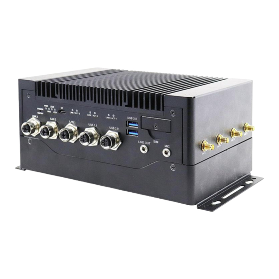
Page 14: Product View
(2x GbE with PoE and 1x 2.5G at LAN1) 4x LEDs for PWR/HDD/ USB 1.1 / 2.0 Ports (M12) Programmable(2x) USB type-C with DP (5Gbps) USB 3.0 Ports 6x LEDs for network status Line Out / Mic Jacks Dual-SIM socket (with cover) MPT-500R/RH Series User Manual... - Page 15 General Information Rear View No. Name Name Antenna holes DSUB15 for COM3/4 (2xRS485) M3 screw for ground HDMI port DSUB15 for 4x DO /4x DI USB 3.0 ports DSUB15 for COM1 (RS232/485) DC-in connector MPT-500R/RH Series User Manual...
- Page 16 Oblique View The oblique view also shows four (4) antenna connectors on the right side. MPT-500R/RH Series User Manual...
-
Page 17: Fuse Dimensions
General Information 1.7 Fuse Dimensions Unit: mm Fuse for MPT-500R: Fuse for MPT-500RH ® ® ® Littlefuse TAC ATO Style Blade Littelfuse Time-lag Fuse 15A, 58V DC 477 series 5A, 400V DC MPT-500R/RH Series User Manual... -
Page 18: Dimensions
1.8 Dimensions Unit: mm MPT-500R/RH Series User Manual... -
Page 19: Chapter 2 Hardware Configuration
Chapter 2 Hardware Configuration The information provided in this chapter includes: • Essential installations • Switches, Jumpers & Connectors... -
Page 20: Essential Installations
For HDD or SSD drive replacement or installation, follow the instructions below. For M.2 SATA card (M-keyed), it is discussed in the section 2.1.2. 1. Release the four screws shown below. 2. Raise the top part of the system to an angle of 120 degrees. MPT-500R/RH Series User Manual... - Page 21 3. The internal components are covered by the 2.5” SSD/HDD tray or drive holder. Remove the single screw (1) to remove the storage holder. Continue to remove the four screws securing the SSD/HDD device to replace or remove it. MPT-500R/RH Series User Manual...
-
Page 22: Installation For M.2 And Mini Pcie Cards
2. To install or replace a card, locate the slot, align the key of the card to the interface, and insert the card slantwise. 3. Push the card down and fix it with the supplied flat head screw (P/N H0220351112200A00P). MPT-500R/RH Series User Manual... -
Page 23: Nano Sim Card Installation
Release the cover by removing the screw as shown below. 2. Push the card holder to release it. Insert the card holder back to its position and push it again to lock it into place. Replace the cover and screw it securely. MPT-500R/RH Series User Manual... -
Page 24: Antenna Installation
1. Thread and fasten the hex nut and the 2. Apply adhesive around here. washer. Then install the antenna. Info: The diameter of the nut is around 6.35 mm (0.25”-36UNC). There are a total of six (6) antennas in the system. MPT-500R/RH Series User Manual... -
Page 25: Mounting Brackets Installation
Hardware Configuration 2.1.5 Mounting Brackets Installation 1. Turn your MPT-500R upside down to attach the mounting brackets and secure the brackets with the supplied screws (P/N H0230461012200A11P as shown below. MPT-500R/RH Series User Manual... -
Page 26: Pinout For M12 Connectors (Power, Usb 2.0, Lan, Com)
Pin Assigment Pin Assigment DC-Input Ground Ground DC-Input • USB 1.1/2.0 Port (M12, 4-pin female A-code) Pin Assigment Pin Assigment Vcc (+5V) Data + Data - Ground- • COM1 Connector Signal Name RS-232 RS-485 DATA- DATA+ Ground Ground MPT-500R/RH Series User Manual... - Page 27 Hardware Configuration MPT-500R/RH Series User Manual...
- Page 28 • COM3 / COM4 Connector Pin Assignment Pin Assignment COM4(D+) COM3(D+) Ground COM4(D-) Ground Ground COM3(D-) Ground • LAN Port (M12, 8-pin, female X-coded) Pin Assigment Pin Assigment MX1+ MX2- MX3- MX4+ MX3+ MX1- MX4- MX2+ MPT-500R/RH Series User Manual...
-
Page 29: Setting The Jumpers
Hardware Configuration 2.2 Setting the Jumpers Set up and configure your MPT-500R by using jumpers for various settings and features according to your needs and applications. Contact your supplier if you have doubts about the best configuration for your use. -
Page 30: Switches, Jumpers & Connectors Locations
J17: Digital I/O Connector ............37 2.5.23 J18: M.2 B-Key (3042/52) Connector ........37 2.5.24 J20: Battery Connector ............38 2.5.25 J21, J22, J23: LAN1,2,3 Connector ........39 2.5.26 J24, J25: USB Type C Flash Connector (Factory use only) ..40 MPT-500R/RH Series User Manual... -
Page 31: Switches And Jumpers
SW1_1: COM3 RS-485 Terminal Register Setting Function COM3 Terminal Disable Pin_1 Off (Default) Pin_1 On COM3 Terminal Enable 2.4.3 SW1_2: COM4 RS-485 Terminal Register Setting Function COM4 Terminal Disable Pin_2 Off (Default) Pin_2 On COM4 Terminal Enable MPT-500R/RH Series User Manual... -
Page 32: Sw2: Digital I/O Test (Factory Use Only)
SW2: Digital I/O test (Factory use only) 2.4.5 SW3_1: Clear CMOS Data Setting Function Normal (Default) Pin_1 Off Pin_1 On Clear CMOS 2.4.6 SW3_2: Clear ME Register Setting Function Normal (Default) Pin_2 Off Pin_2 On Clear ME MPT-500R/RH Series User Manual... -
Page 33: Jp1: At/Atx Mode Selection
Hardware Configuration 2.4.7 JP1: AT/ATX Mode Selection Function Pin closed Illustration (default) 2.4.8 JP2: POE Mode Setup (Factory use only) Pin Assigment Pin Assigment 4266_AUTO 4266_MID 4266_RESET Ground 4266_MSD Ground MPT-500R/RH Series User Manual... -
Page 34: Jp3: Sierra 5G Wireless Card Usb/Pcie I/F Selection
2.4.9 JP3: Sierra 5G Wireless Card USB/PCIE I/F Selection (Default) PCIE MPT-500R/RH Series User Manual... -
Page 35: Connectors
Hardware Configuration 2.5 Connectors 2.5.1 CN1: HDMI Connector 2.5.2 CN2: USB3 Type A Connector (supports USB3 Gen2) 2.5.3 CN3: SATA Connector MPT-500R/RH Series User Manual... -
Page 36: Cn4: Nano Sim Card Connector
2.5.4 CN4: Nano SIM Card Connector 2.5.5 CN5: USB3 Type A Connector (supports USB3 Gen1) 2.5.6 CN9: Type C Connector (supports USB3 Gen1) MPT-500R/RH Series User Manual... -
Page 37: Cpu_Fan1: Cpu Fan Power Connector
Hardware Configuration 2.5.7 CPU_FAN1: CPU Fan Power Connector Assigment Ground +12V Rotation detection Control 2.5.8 J1: VGA Connector (HRS_DF11-16DP-2DSA(08)) Pin Signal Name Pin Signal Name CRT_R CRT_G CRT_B DDC_DATA CRT_HSYN CRT_VSYN DDC_CLK MPT-500R/RH Series User Manual... -
Page 38: J2: Com3,4 Rs-485 Connector
2.5.9 J2: COM3,4 RS-485 Connector (HK_DF11-10S-PA66H) Signal Name Signal Name RS485-DATA3- RS485-DATA4- RS485-DATA3+ RS485-DATA4+ MPT-500R/RH Series User Manual... -
Page 39: J3: Com1 Connector
RTS, Request to send CTS, Clear to send RI, Ring indicator Not Used COM1 is jumper-less for RS-232, RS-422 and RS-485 and configured with BIOS Selection. Signal Name RS-232 RS-422 RS-485 DATA- DATA+ Ground Ground Ground MPT-500R/RH Series User Manual... -
Page 40: J4: Espi Debug 80 Port (Factory Use Only)
2.5.11 J4: ESPI Debug 80 Port (Factory use only) 2.5.12 J5: SPI ROM Flash Connector (Factory use only) MPT-500R/RH Series User Manual... -
Page 41: J6: Audio Connector
Hardware Configuration 2.5.13 J6: Audio Connector (HK_DF11-12S-PA66H) Pin Signal Name Pin Signal Name LINEOUT_R LINEOUT_L Ground JD_FRONT MIC-R MIC_L Ground JD_MIC1 2.5.14 J7: USB_2.0 Connector (E-Call_0110-161-040) Pin Assigment Ground Note: USB Enable/Disable Selection by BIOS MPT-500R/RH Series User Manual... -
Page 42: J8: Usb_1.1 Connector
2.5.15 J8: USB_1.1 Connector (E-Call_0110-161-040) Pin Assigment Ground Note: USB Enable/Disable Selection by BIOS 2.5.16 J10: External Super CAP Connector (E-Call_0110-071-060) Pin Assigment +12VDUAL +12VDUAL +12VDUAL Ground Ground Ground MPT-500R/RH Series User Manual... -
Page 43: J11: Mini Pcie Connector
Hardware Configuration 2.5.17 J11: Mini PCIE Connector with PCIe (x1), USB 2.0, SIM Card 2.5.18 J12: M.2 M-Key (2280) Connector with PCIe (x1) 2.5.19 J13: SATA HDD Power Connector (E-Call_0110-071-040) Pin Assigment Ground Ground +12V MPT-500R/RH Series User Manual... -
Page 44: J14: Poe Debug Setting (Factory Use Only)
2.5.20 J14: POE Debug Setting (Factory use only) 2.5.21 J15: DC_IN 12V Power Connector (HK_ATX4PT-NY46) Pin Signal Name Pin Signal Name +12V Ground +12V Ground MPT-500R/RH Series User Manual... -
Page 45: J17: Digital I/O Connector
Hardware Configuration 2.5.22 J17: Digital I/O Connector (HK_DF11-10S-PA66H) Pin Signal Name Pin Signal Name OUT0 OUT1 OUT2 OUT3 Power Ground 2.5.23 J18: M.2 B-Key (3042/52) Connector with PCIe (x1), USB 2.0, USB 3.0, SIM Card MPT-500R/RH Series User Manual... -
Page 46: J20: Battery Connector
J19 is an 8-pin header that provides interfaces for the following functions: Pin Signal Name Pin Signal Name Power BTN- Power BTN+ HDD LED+ HDD LED- Ground Reset BTN+ Power LED+ Ground 2.5.24 J20: Battery Connector (Molex_53047-0210) MPT-500R/RH Series User Manual... -
Page 47: J21, J22, J23: Lan1,2,3 Connector
Hardware Configuration 2.5.25 J21, J22, J23: LAN1,2,3 Connector (HRS_DF11-8DP- 2DSA(08)) Pin Signal Name Pin Signal Name MDI_P0 MDI_N0 MDI_P1 MDI_N1 MDI_N2 MDI_P2 MDI_P3 MDI_N3 MPT-500R/RH Series User Manual... -
Page 48: J24, J25: Usb Type C Flash Connector (Factory Use Only)
2.5.26 J24, J25: USB Type C Flash Connector (Factory use only) MPT-500R/RH Series User Manual... -
Page 49: Chapter 3 Driver Installation
Chapter 3 Driver Installation The information provided in this chapter includes: • ® Intel Chipset Software Installation Utility • VGA Driver Installation • HD Audio Driver Installation • ® Intel ME Drivers Installation • LAN Driver Installation... -
Page 50: Introduction
INF files for Plug & Play function for the chipset components. Follow the instructions below to complete the installation. 1. Insert the DVD enclosed in the package. Click Intel and then Intel(R) Elkhartlake Chipset Drivers. MPT-500R/RH Series User Manual... - Page 51 4. Click Yes to accept the software license agreement and proceed with the installation process. 5. Click Install to proceed with the installation process. 6. The driver has been completely installed. Click Finish to complete the setup process. MPT-500R/RH Series User Manual...
-
Page 52: Vga Driver Installation
3.3 VGA Driver Installation 1. Click Intel and then Intel(R) Elkhartlake Chipset Drivers. 2. Click Intel(R) Elkhartlake Graphics Driver. 3. Click Begin Installation to continue. 4. Click Yes to agree with the license agreement. MPT-500R/RH Series User Manual... - Page 53 Driver Installation 5. Click Start. 6. When the installation has been completed, click Finish. MPT-500R/RH Series User Manual...
-
Page 54: Hd Audio Driver Installation
2. Click Realtek High Definition Audio Driver. 3. On the Welcome screen of the InstallShield Wizard, click Next to start the installation. 4. When the InstallShield Wizard has finished installing the Realtek Audio Driver, click Finish. MPT-500R/RH Series User Manual... -
Page 55: Intel(R) Me Drivers Installation
3. Click Next to accept the terms in the License Agreement. 4. Click Next to install to the default folder, or click Change to choose another destination folder. 5. When you have successfully installed the components, click Finish. MPT-500R/RH Series User Manual... -
Page 56: Lan Driver Installation
5. In the Software License Agreement screen, click Next to accept the terms in the license agreement. 6. In the Setup Options screen, click Next. 7. The wizard is now ready to begin installation. Click Install. 8. In the Install wizard Completed screen, click Finish. MPT-500R/RH Series User Manual... -
Page 57: Chapter 4 Bios Setup
Chapter 4 BIOS Setup This chapter the different settings available in the AMI describes BIOS that comes with the board. The topics covered in this chapter are as follows: • Main Settings • Advanced Settings • Chipset Settings • Security Settings •... -
Page 58: Introduction
These defaults have been carefully chosen by both AMI and your system manufacturer to provide the absolute maximum performance and reliability. Changing the defaults could make the system unstable and crash in some cases. MPT-500R/RH Series User Manual... -
Page 59: Main Settings
4.3 Main Settings BIOS Setting Description System Date Sets the date. Use the <Tab> key to switch between the Date elements. System Time Set the time. Use the <Tab> key to switch between the Time elements. MPT-500R/RH Series User Manual... -
Page 60: Advanced Settings
Advanced Settings: • CPU Configuration • PCH-FW Configuration • Trusted Computing • Super IO Configuration • Hardware Monitor • USB Configuration • Network Stack Configuration • Integrated Peripherals • NVMe Configuration MPT-500R/RH Series User Manual... - Page 61 BIOS Setup 4.4.1 CPU Configuration MPT-500R/RH Series User Manual...
- Page 62 4.4.2 PCH-FW Configuration MPT-500R/RH Series User Manual...
- Page 63 TPM 1.2 will restrict support to TPM 1.2 devices only. TPM 2.0 will restrict support to TPM 2.0 devices only. Device Select Auto will support both with the default being set to TPM 2.0 deices if not found, and TPM 1.2 device will be enumerated. MPT-500R/RH Series User Manual...
- Page 64 Sets parameters of Serial Port 4 (COMD). The power failure resume control logic of the Power Failure F81866 is used to recover the system to a pre-defined state after AC power failure. Serial Port 1 Configuration MPT-500R/RH Series User Manual...
- Page 65 BIOS Setup Serial Port 3 Configuration Serial Port 4 Configuration MPT-500R/RH Series User Manual...
- Page 66 70 ℃, 80 ℃, 90 ℃ Temperatures / Voltages These fields are the parameters of the hardware monitoring function feature of the motherboard. The values are read-only values as monitored by the system and show the PC health status MPT-500R/RH Series User Manual...
- Page 67 The maximum time the device will take before it properly reports itself to the Host Controller. “Auto” uses default value for a Root port it is Device power-up delay 100ms. But for a Hub port, the delay is taken from Hub descriptor. MPT-500R/RH Series User Manual...
- Page 68 4.4.7 Network Stack Configuration MPT-500R/RH Series User Manual...
- Page 69 BIOS Setup 4.4.8 Integrated Peripherals 4.4.9 NVMe Configuration MPT-500R/RH Series User Manual...
-
Page 70: Chipset Settings
Sets the GTT size as 2MB, 4MB, or 8MB. Sets the aperture size as 128MB, 256MB, 512MB, 1024MB or 2048MB. Aperture Size Note: Above 4GB MMIO BIOS assignment is automatically enabled when selecting 2048 MB aperture. To use this feature, disable CSM support. MPT-500R/RH Series User Manual... - Page 71 Enables / Disables the SATA device. Controller(s) SATA Mode Determines how SATA controller(s) operate. Options: Selection AHCI / Intel RST Premium Serial ATA Enables / Disables serial ports. Ports SATA Ports Hot Enables / Disables SATA Ports HotPlug. Plug MPT-500R/RH Series User Manual...
-
Page 72: Security Settings
This section allows you to configure, improve your system, and set up some system features according to your preference. BIOS Setting Description Administrator Sets an administrator password for the setup utility. Password User Password Sets a user password. Secure Boot Configures Secure Boot. MPT-500R/RH Series User Manual... - Page 73 Restore Factory Forces system to user mode. Install factory default Keys Secure Boot key databases. Enables expert users to modify Secure Boot Policy Management variables without full authentication. MPT-500R/RH Series User Manual...
-
Page 74: Boot Settings
Number of seconds to wait for setup activation key. 65535 (0xFFFF) means indefinite waiting. Bootup NumLock State Selects the keyboard NumLock state. Quiet Boot Enables / Disables Quiet Boot option. Boot Option Priorities Sets the system boot order. MPT-500R/RH Series User Manual... -
Page 75: Save & Exit Settings
Restore Defaults Restores / Loads defaults values for all the setup options. Save as User Defaults Saves the changes done so far as user defaults. Restore User Defaults Restores the user defaults to all the setup options. MPT-500R/RH Series User Manual... -
Page 76: Appendix
Appendix This section provides the mapping addresses of peripheral devices and the sample code of watchdog timer configuration. • I/O Port Address Map • Interrupt Request Lines (IRQ) • Watchdog Timer Configuration • Software Development Kit for WDT.DLL... -
Page 77: I/O Port Address Map
Standard SATA AHCI Controller 0x00003080-0x00003083 Standard SATA AHCI Controller 0x00003060-0x0000307F Standard SATA AHCI Controller 0x00000020-0x00000021 Programmable interrupt controller 0x00000024-0x00000025 Programmable interrupt controller 0x00000028-0x00000029 Programmable interrupt controller 0x0000002C-0x0000002D Programmable interrupt controller 0x00000030-0x00000031 Programmable interrupt controller 0x00000034-0x00000035 Programmable interrupt controller MPT-500R/RH Series User Manual... - Page 78 PCI Express Root Complex 0x00000D00-0x0000FFFF PCI Express Root Complex 0x0000EFA0-0x0000EFBF Intel(R) SMBus Controller - 4B23 0x00002000-0x000020FE Motherboard resources 0x00000060-0x00000060 Standard PS/2 Keyboard 0x00000064-0x00000064 Standard PS/2 Keyboard 0x00003000-0x0000303F Intel(R) UHD Graphics 0x00000040-0x00000043 System timer 0x00000050-0x00000053 System timer MPT-500R/RH Series User Manual...
-
Page 79: Interrupt Request Lines (Irq)
Intel(R) Ethernet Controller (3) I225-IT #3 IRQ 4294967283 Intel(R) Ethernet Controller (3) I225-IT #3 IRQ 4294967282 Intel(R) Ethernet Controller (3) I225-IT #3 IRQ 4294967291 Intel(R) Management Engine Interface #1 IRQ 4294967292 Intel(R) UHD Graphics IRQ 0 System timer MPT-500R/RH Series User Manual... -
Page 80: Watchdog Timer Configuration
Fintek 81866, program abort.\n"); return(1); }//if (SIO == 0) if (argc != 2) printf(" Parameter incorrect!!\n"); return (1); bTime = strtol (argv[1], endptr, 10); printf("System will reset after %d seconds\n", bTime); if (bTime) EnableWDT(bTime); } else DisableWDT(); } return 0; MPT-500R/RH Series User Manual... - Page 81 DisableWDT(void) unsigned char bBuf; Set_F81866_LD(0x07); //switch to logic device 7 bBuf = Get_F81866_Reg(0xFA); bBuf &= ~0x01; Set_F81866_Reg(0xFA, bBuf); //disable WDTO output bBuf = Get_F81866_Reg(0xF5); bBuf &= ~0x20; bBuf |= 0x40; Set_F81866_Reg(0xF5, bBuf); //disable WDT //--------------------------------------------------------------------------- MPT-500R/RH Series User Manual...
- Page 82 Init_Finish; } F81866_BASE = 0x00; result = F81866_BASE; Init_Finish: return (result); //--------------------------------------------------------------------------- void Unlock_F81866 (void) outportb(F81866_INDEX_PORT, F81866_UNLOCK); outportb(F81866_INDEX_PORT, F81866_UNLOCK); //--------------------------------------------------------------------------- void Lock_F81866 (void) outportb(F81866_INDEX_PORT, F81866_LOCK); //--------------------------------------------------------------------------- void Set_F81866_LD( unsigned char LD) Unlock_F81866(); outportb(F81866_INDEX_PORT, F81866_REG_LD); outportb(F81866_DATA_PORT, LD); Lock_F81866(); MPT-500R/RH Series User Manual...
- Page 83 #defineF81866_INDEX_PORT (F81866_BASE) #defineF81866_DATA_PORT (F81866_BASE+1) //--------------------------------------------------------------------------- #defineF81866_REG_LD 0x07 //--------------------------------------------------------------------------- #define F81866_UNLOCK 0x87 #defineF81866_LOCK 0xAA //--------------------------------------------------------------------------- unsigned int Init_F81866(void); void Set_F81866_LD( unsigned char); void Set_F81866_Reg( unsigned char, unsigned char); unsigned char Get_F81866_Reg( unsigned char); //--------------------------------------------------------------------------- #endif // F81866_H MPT-500R/RH Series User Manual...
-
Page 84: Software Development Kit For Wdt.dll
⚫ For 32-bit environment: Step 1: Copy the file KMUI32_1K.SYS to <%WINDIR%>\SYSTEM32\DRIVERS. Step 2: The following parameters must be written to your registry. HKLM,"System\CurrentControlSet\Services\KMUI32_1K","ErrorCo ntrol",%REG_DWORD%,0x00000001 HKLM,"System\CurrentControlSet\Services\ KMUI32_1K","Type",%REG_DWORD%,0x00000001 HKLM,"System\CurrentControlSet\Services\ KMUI32_1K","Start",%REG_DWORD%,0x00000000 HKLM,"System\CurrentControlSet\Services\ KMUI32_1K","DisplayName",%REG_SZ%,"KMUI32_1K" Step 3: Restart the system. MPT-500R/RH Series User Manual... - Page 85 The following parameters must be written to your registry. HKLM,"System\CurrentControlSet\Services\KMUI64_1K","ErrorControl", %REG_DWORD%,0x00000001 HKLM,"System\CurrentControlSet\Services\ KMUI64_1K","Type",%REG_DWORD%,0x00000001 HKLM,"System\CurrentControlSet\Services\ KMUI64_1K","Start",%REG_DWORD%,0x00000000 HKLM,"System\CurrentControlSet\Services\ KMUI64_1K","DisplayName",%REG_SZ%,"KMUI64_1K" Step 3: Restart the system. Note: Do not install both of the 32-bit and 64-bit drivers on an operating system. MPT-500R/RH Series User Manual...
- Page 86 Output : Always return 1. Note: This function should be invoked before the program closes and it will release the device driver and memory for ib_wdt.dll. If the program is closed without calling this routine, resource leak may occur. MPT-500R/RH Series User Manual...
- Page 87 Output : Always return “0” For further information, refer to the datasheet for WDT or contact your sales representative. extern "C" __declspec(dllexport) int __stdcall DisableWDT(int); Input : Dummy data and will be ignored. Output : Always return “0” MPT-500R/RH Series User Manual...
- Page 88 GPIO_6 are the output functions. Output : Dummy data and should be ignored. extern "C" __declspec(dllexport) int __stdcall SetDioOutputMask(int); Input : Hardware parameter for digital I/O output function call For further information, refer to the following explanation of “SetDioInputMask” routine. MPT-500R/RH Series User Manual...
- Page 89 Set GPIO_5 to GPIO_6 to HIGH\n"); Sleep(500); if (_kbhit()) break; }//if (kbhit()) }//while(1) }//if ((*lpIsDioAvailable)(0)) Note: Be sure to set up the input / output for GPIO bits in BIOS identically with the GPIO hardware information above. MPT-500R/RH Series User Manual...
-
Page 90: Motherboard Mcu Isp Specifications
Note: Before using the ISP, your software engineer has to make sure the firmware version (GET_FORMWARE_VERSION) MUST be as follows to make the ISP function workable. Major version is 0. Minor version is 0. Build version is 1 (or above). MPT-500R/RH Series User Manual... - Page 91 Protocol uses 16-bit CCITT CRC to verify data integrity. P(x) = X unsigned calc_crc(unsigned char *data, unsigned unsigned start) { unsigned I, k, q, c, crcval; crcval=start; (I=0; I<n; I++) { c=data(I) & 0xFF; q=(crcval^c) & 0x0F; crcval=(crcval>>4)^(q*0x1081); q=(crcval^(c>>4)) & 0x0F; crcval=(crcval>>4)^(q*0x1081); return crcval; MPT-500R/RH Series User Manual...
- Page 92 Header Size Command Data 0xFF Size of GET_FIRMWARE_VERSION 0xEE Version Version structure Structure BSL Version Structure Field Type Description Major Version Byte Major version number Minor Version Byte Minor version number Build Byte Build version number MPT-500R/RH Series User Manual...
- Page 93 ⚫ Setting Power-Off Delay Timer Parameter: SET_POWER_OFF_DELAY_TIMER Sets power off delay timer. Request: Header Size Command Data0 Data1 CRC 0xFF 0x02 SET_POWER_OFF_DELAY_TIMER N 0xEE (mins) (secs) Reply Header Size Command Data 0xFF 0x00 SET_POWER_OFF_DELAY_TIMER None 0xEE MPT-500R/RH Series User Manual...
- Page 94 0xFF 0x00 GET_STATUS None 0xEE Reply: Header Size Command Data 0xFF 0x04 GET_STATUS Status 0xEE structure BSL Version Structure Field Type Description Power on delay timer Word Byte4+ Byte5 Power off delay timer Word Byte6+ Byte7 MPT-500R/RH Series User Manual...
Need help?
Do you have a question about the MPT-500R and is the answer not in the manual?
Questions and answers