Table of Contents
Advertisement
Quick Links
This Service manual
is consist of "REM-M4a", "
"AD-G5","CR-WG5","CA-G5"
FM-GS",
SERVICE
MANUAL
<7
TAD-G5
(GERMANY)
(SPAIN)
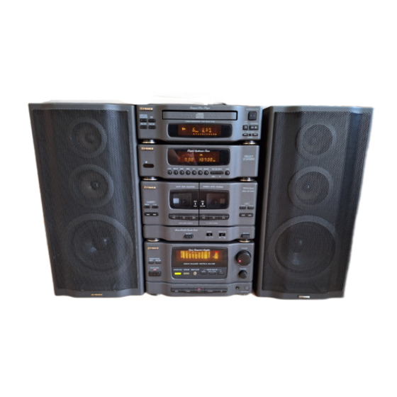
CD
Mini
Component
System
Sanyo
DCT4&4A
DCT 55 DK
Dalby
noise
reduction
manufactured
under
license
from
Dolby
Laboratories
Licensing Corporation
"DOLBY"
Laboratories
Licensing Carporation
Contents
SPECIFICATION
& ACCESSORIES)
REMOTE
CONTROLLER
UNIT
TUNER
UNIT
ADJUSTMENT
EXPLODED
VIEW
PARTS
LIST
IC
BLOCK
DIAGRAM
SCHEMATIC
DIAGRAM
WIRING
DIAGRAM
CD
PLAYER
UNIT
...................
LASER
BEAM
SAFETY
PRECATION
....
CO
MECHANISM
REMOVAL
6-3.
6-4.
6-5.
BLOCK
DIAGRAM
6-6.
6-7.
6-8.
6-9.
MECHANISM)
....
6-10. VOLTAGE
TABLE
TA
RON
=
oes
Loe)
=
DODAQANAA
~ an
ff nN
and the double-D symbol U0 are trademarks of Dolby
26
28
PRODUCT
CODE
No.
129
364
06 (Germany / White)
129
364
07 (Germany / Black)
129
364
08 (Spain / Black)
6-11. SCHEMATIC
DIAGRAM
.............
DIAGRAM
......
6-13.1C
BLOCK
DIAGRAM
......0......
;
7.
TAPE.
DECK
UNIT:
6 csi:8 sig 2604 4 oie
te
7-1.
ADJUSTMENT
DECK
& TORQUE
......
fede
EXPLODED
VIEW
os -.sk a kspcae
ds vale
128,
(PARVS:
TIS TO £62.05
oon Og Be Pica. Seu ees
7-4.
EXPLODED
VIEW
(TAPE
MECHANISM
7-5.
LIST (TAPE
MECHANISM
"1t")
7-6.
EXPLODED
VIEW (TAPE
MECHANISM
"2"
7-7.
LIST (TAPE
MECHANISM
"2")
7-8.
IG BLOCK
DIAGRAM
7-9.
WIRING
DIAGRAM
.................
7-10. SCHEMATIC
DIAGRAM
.............
8.
AMPLIFIER
UNIT
2.0.0...
..0. 0.000005
8-1.
EXPLODED
VIEW
8-2.
PARTS
LIST
8-3.
SCHEMATIC
DIAGRAM
8-4.
WIRING
DIAGRAM
8-5.
DIAGRAM
9.
FOR
REPAIRABLE
30
31
34
38
38
40
4
44
45
46
47
48
50
SEPARATED
52
52
53
57
58
68
REFERENCE
No.
WM-580633
Advertisement
Table of Contents


Need help?
Do you have a question about the TAD-G5 and is the answer not in the manual?
Questions and answers