Table of Contents
Advertisement
Quick Links
Advertisement
Table of Contents

Related Manuals for Lode MRI Ergometer

Summary of Contents for Lode MRI Ergometer
- Page 1 918905/6/7/8UE User guide MRI Ergometer Lode BV Groningen, the Netherlands 0344...
- Page 2 User Guide. Intended Use A Lode ergometer is a diagnostic tool intended to be used as a stress test device in a medical environment. The main goal of the use of a Lode ergometer is to create reproducible stress tests.
- Page 3 Voltage selection should be done by a technician! Possible hazards Using the MRI Ergometer according to intended use, contra indications, maintenance, precaution and common sense stated above may not eliminate all hazards. Possible residual hazards could be: wrong installation, wrong use, wrong dose, wrong interpretation of readings, mechanical breakdown of parts, software failure.
- Page 4 Operator’s Manual MRI Ergometer which is potentially dangerous. The potential equalization conductor works to remove this hazard. Refer to IEC 60601-1, Clause 8, POTENTIAL EQUALIZATION CONDUCTOR, for application requirements.
- Page 5 Operator’s Manual MRI Ergometer LIST OF SYMBOLS USED Read manufacturer’s guide, advises marking for Medical Devices 0344 and instructions and manual classified as Im, IIa or IIb according to the MDD 93/42.EEC. Device of TYPE B Tested and certified to U.S. and...
- Page 6 Operator’s Manual MRI Ergometer Copyright Lode BV, April 2018, All rights reserved.
- Page 7 MRI Ergometer WARNING !! The MRI ergometer is a MRI-conditional product for which the safety precautions as described below need to be fulfilled when using the product. Since the MRI ergometer Power Unit (918400) contains parts that are electromagnetic it should not be placed within a radius of 2 meters to your MRI-Magnet.
-
Page 8: Table Of Contents
MRI E .............. 17 OVING THE RGOMETER WITH THE CARRIER ....................19 NSTALLATION ROCEDURE USING THE MRI ERGOMETER– QUICK START ............21 ) ..................21 ANUAL MENU STAND ALONE MAIN MENU ......................22 SYSTEM PARAMETER ................... 24 ........................24 ET DISPLAY 6.1.1 Power ........................ - Page 9 Description of the MRI Ergometer Pedal (918905)......... 35 Identification of parts ................... 35 Description of the Adapter frame (Siemens) ..........35 B.2.1 Place the MRI Ergometer on the patient table ........36 Description of the MRI Ergometer Pedal Lowfoot (918906) ......38 Identification of parts ................... 38 Description of Fixation to the Patient Support (Philips) ......
-
Page 10: Introduction
1 Introduction Congratulations on your new MRI Ergometer! This device will provide you optimal test possibilities. Your test subject will also enjoy using the MRI Ergometer (for its silent operating circumstances and its adjustability). The MRI Ergometer has standard possibilities for adjusting the workload of the ergometer. -
Page 11: Description Of The Mri Ergometer
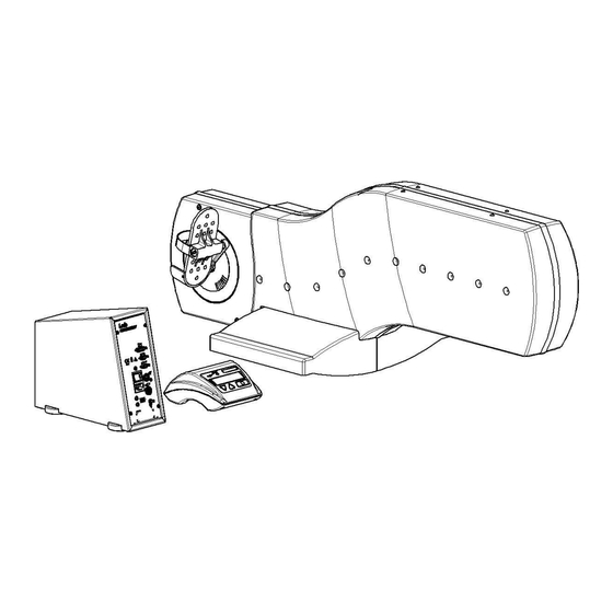
Operator’s Manual MRI Ergometer 2 Description of the MRI Ergometer The MRI Ergometer is a solid ergometer that can be used special research and test during MRI scanning. The following will be described in this chapter: Identification of parts ... -
Page 12: Main Unit Panel
Display A (2x16 characters) directed to test subject down button up button confirmation button ergometer type indication Main unit panel The main unit panel of the MRI Ergometer contains the following elements: Fig 2: Power Unit connections Control unit connector RS232 input RS232 output Analog i/o... -
Page 13: Adjustments
Adjustments See Appendix 7.4B for Description of the MRI Ergometer Pedal (918905) See Appendix 7.4C for Description of the MRI Ergometer Pedal Lowfoot (918906). See Appendix 7.4D for Description of the MRI Ergometer Up/Down (918907). See Appendix 7.4E for Description of the MRI Ergometer Push/Pull (918908). -
Page 14: Installing The Mri Ergometer
Moving the MRI Ergometer. Installation procedure of the MRI Ergometer. What should be in the MRI Ergometer package Before installing the MRI Ergometer, check that the following items are included in the package: User guide part. no. 918905/6/7/8UE ... -
Page 15: Fixing The Mri Ergometer To The Adapter Frame
In Fig 4 an exploded view of all elements are shown: 1. The MRI Ergometer. 2. Foot cover left and right. 3. Bolts for fixing the MRI Ergometer to the patient table (8X). 4. Washer (8X). 5. The adapter frame. -
Page 16: Adjusting The Handgrips
Instead the MRI Ergometer is directly mounted to the Patient table, see Appendix. To mount the MRI Ergometer (1) onto the adapter frame (5) place (5) onto a firm surface, e.g. a clean floor surface. Remove (2) from the MRI Ergometer and place the MRI Ergometer onto (5). -
Page 17: Moving The Mri Ergometer With The Carrier
Moving the MRI Ergometer with the carrier The carrier is used for transporting the MRI Ergometer and placing it on and of the MRI- System. The wheels of the carrier, Fig 6-6 are provided with brakes, which can be used for parking the carrier when it is not in use. - Page 18 MRI Ergometer Fig 6: Moving the ergometer In Fig 7 is indicated which items must be handled for placing the MRI Ergometer in correct position on the patient-support of the MRI-system. First position the carrier with the MRI Ergometer on it, near the patient table of the MRI-scanner. The carrier must then be in lifted (turn 2) turned-over in position (turn 1).
-
Page 19: Installation Procedure
Place the Power Unit not clods than 2 meters in the vicinity of the MRI bore. Connect the cord to the MRI Ergometer and the Power Unit with the support cable. Connect the Control Unit and the MRI Ergometer with the supported cable. - Page 20 Also make sure that the cables are not bend in curls, but they should be laid on the floor as straight as possible under the conditions. 10. Switch in the power mains of the Power Unit. The MRI Ergometer is now ready for use.
-
Page 21: Using The Mri Ergometer- Quick Start
Chapter 3: Switch on the MRI Ergometer with the mains switch on the back panel (Fig. 9 Back panel connections). The default start up menu of the control panel is the entrance to the MAIN MENU. -
Page 22: Main Menu
Operator’s Manual MRI Ergometer 5 Main menu When the ergometer is started after pressing the confirmation button ( ) you will enter the MAIN MENU. LODE ERGOMETER MAIN MENU The following submenus are selectable from the main menu: - TERMINAL... - Page 23 Operator’s Manual MRI Ergometer...
-
Page 24: System Parameter
Operator’s Manual MRI Ergometer 6 System parameter MAIN MENU SYSTEM PARAMETER In the System Parameters different ergometer specific settings can be carried out, from which the most important are: Adjusting the readout parameters. Trainings mode selection (hyperbolic, linear, fixed Torque). -
Page 25: Rpm
Operator’s Manual MRI Ergometer it takes 400/25=16 seconds before this workload is achieved. This holds also for workload reduction. Only when RPM drops below 25, the workload is removed at once, because the pedal torque becomes very high. Workload is put on the brake when RPM is more than, or equal to 30 RPM. -
Page 26: Torque
Operator’s Manual MRI Ergometer ♥= 80/m P= 100W MANUAL 6.1.4 Torque TORQUE Switch ON or OFF the torque in the readout. The torque is displayed in Newton meter. The torque (T) is coupled to Workload (P) and RPM (n) by the formula: P [W] = ( 2 * π... -
Page 27: Distance
Operator’s Manual MRI Ergometer 6.1.6 Distance DISTANCE Switch the distance ON or OFF. The distance is shown in the display as: → = 99,9 km, expressing the distance in km. The formula reads: Distance [Km] = (100/36*(1.32+P[W]*(0.042-0.00075*sqrt(P)))*P/(P+2))*time[hours] This is a fictive formula, holding only for average cycle conditions. It should not be used for diagnostic purposes. -
Page 28: Set Mode
Operator’s Manual MRI Ergometer Set mode SYSTEM PARAMETER SET MODE Set mode is used to define which parameter can be adjusted during the exercise test in MANUAL mode with▼▲ keys. With parameter one of the ergometry variables is meant, like workload, torque, heart rate and linear constant alpha. -
Page 29: Settings
Operator’s Manual MRI Ergometer The torque T is adjusted in Nm: T = 10.4 Nm MANUAL Settings Under settings all device specific and interface adjustments can be made. It concerns all those items not related directly to ergometry. SYSTEM PARAMETER SETTINGS 6.4.1... -
Page 30: Testfunctions
Operator’s Manual MRI Ergometer KEYBOARD ON/OFF This is a convenient function to use together with TERMINAL as default start menu when you use the ECG system as the controlling device and do no want a test subject to interrupt the exercise test. -
Page 31: Language
Operator’s Manual MRI Ergometer P IN/OUT ANALOG 1 V = 100 W For the best accuracy it is advised to use this scaling. This restricts the P_in to 500 W and P_out to 1000 W. Only if you need higher workloads, increase to 200 or 500 watt/volt. If you are unsure, contact your supplier. -
Page 32: Specifications
≙ Input voltage for external control 100,200 or 500 W 1 V (max. 300 W). ≙ Safety class MRI Ergometer I type B, IEC 601-1 chapter 18, 19 and 20. Leakage current < 0.4 mA. Isolation resistance > 4 MΩ. - Page 33 Zero load < 8 W at 60 rpm Noise level +/- 60 dB at workload 200 W/60 rpm +/-80 cm from crank. The MRI Ergometer is manufactured in accordance with: ISO 9001 ISO 13485 IEC 601-1 FDA510K...
-
Page 34: A Maintenance
Note: make sure that the fuses that are in the MRI Ergometer match the set voltage (115 V: 2 x 1,25 A slow; 230 V :2 x 0,63 A slow). -
Page 35: B Description Of The Mri Ergometer Pedal (918905)
Operator’s Manual MRI Ergometer Description of the MRI Ergometer Pedal (918905) The MRI Ergometer is a solid ergometer that can be used for special research and tests during MRI scanning. The following will be described in this appendix: Identification of parts ... -
Page 36: Place The Mri Ergometer On The Patient Table
Fig 10-3 of the adapter frame against the case of the patient table Fig 10-4. After that lock the MRI Ergometer with the adapter frame to the patient table by turning the handles Fig 10-1 vertically. - Page 37 Operator’s Manual MRI Ergometer...
-
Page 38: C Description Of The Mri Ergometer Pedal Lowfoot (918906)
There is no adapter frame, or any other interface, see Fig 12, between the MRI Ergometer, see Fig 12-2 and the patient table, Fig 12-1 of the MRI-Scanner, i.e. the MRI Ergometer is direct mounted and fixed onto the patient table. To this end the patient table is modified at the Lode workshop. -
Page 39: Adjusting The Handgrips
3. dovetail multiple nut part in patient table (2X). 4. foot cover left and right. 5. MRI Ergometer. 6. Bolts for fixing the MRI Ergometer to the patient table (8X). 7. washer (8X) 8. nuts pressed into patient table at Lode workshop (8X) - Page 40 Operator’s Manual MRI Ergometer To mount the MRI Ergometer remove (4) and place the MRI Ergometer on the patient table. Place all eight (6) plus (7) and fix them the appropriate (MRI compatible, i.e., non-ferro) tool. Apply the normal hand force to fix the bolts. Then replace both (4) To mount the hand grip set.
-
Page 41: D Description Of The Mri Ergometer Up/Down (918907)
Operator’s Manual MRI Ergometer Description of the MRI Ergometer Up/Down (918907) The MRI Ergometer is a solid ergometer that can be used for special research and tests during MRI scanning. The following will be described in this appendix: Description of the MRI Ergometer. -
Page 42: Identification Of Parts
Operator’s Manual MRI Ergometer Fig 14: MRI Ergometer D.2 Identification of parts If you want to exchange the cranks, first disassemble the pedal-arms. The crank can be unlocked by sliding the locking device, Fig 15-1 towards the crank pin. After that you take the crank of the axle Fig 15-2 and replace it on the opposite end of the axle. -
Page 43: Description Of The Adapter Frame
Fig 15: Identification of Parts D.3 Description of the Adapter frame The adapter frame, see Fig 16 is the interface between the MRI Ergometer and the patient table of the MRI-Scanner, i.e. it connects and fixes the MRI Ergometer to the patient table. -
Page 44: Description Of The Leg-Support
Operator’s Manual MRI Ergometer Fig 16: Adapter frame D.3.1 Description of the leg-support The leg support is used to tie down the upper legs in order to make the desired scan. Adjustments can be made to adapt to different test persons: first you have to adjust the angle of the leg support, Fig 17-1. -
Page 45: Place The Mri Ergometer On The Siemens Patient Table
Fig 18-2 of the adapter frame against the case of the patient table Fig 18-4. After that lock the MRI Ergometer with the adapter frame to the patient table by turning the handles Fig 16-4 vertically. -
Page 46: Place The Mri Ergometer On The Philips Patient Table
Fig 19: Placing the MRI Ergometer on Philips D.6 Description of the Carrier with Ergometer for General Electric The MRI Ergometer can also be mounted on the Signa Horizon or Twin Speed of GE Medical Systems. There are three main assemblies in the MRI Ergometer (Fig 20): 1. - Page 47 (Fig 21: nr.1) is lifted. Then move the MRI Ergometer to the patient-support and place it in such position, that the fixing-hook is above the handgrip of the patient-support. Now turn the handle (Fig 22: detail 1) to the right and the MRI Ergometer is fixed to the patient-support.
- Page 48 Operator’s Manual MRI Ergometer Fig 21: Carrier for GE The distance between the leg-support (Fig 21 nr 4) and the pedal shoes can be adjusted by loosening the lock pins (Fig 21: nr 5), set the leg-support in the correct position and lock it again with the lock pin.
- Page 49 MRI-System. Because the carrier is locked to the patient support, the carrier with MRI Ergometer is placed into the correct position automatically. When the carrier is in the correct position, it can be fixed to the patient-table by turning the hand wheel (Fig 21: nr.2) clockwise.
-
Page 50: E Description Of The Mri Ergometer Push/Pull (918908)
E.1 Description of the MRI Ergometer On both sides of the MRI Ergometer there is a pedal arm with pedal shoe Fig 24-1 They are both connected with a crank Fig 24-2. You can move the pedal shoes independently because in each crank is a freewheel. -
Page 51: Place The Mri Ergometer On The Siemens Patient Table
Fig 26-3 of the adapter frame against the case of the patient table Fig 26-4. After that lock the MRI Ergometer with the adapter frame to the patient table by turning the handles Fig 26-1 vertically. -
Page 52: Place The Mri Ergometer On The Philips Patient Table
Fig 27-2 of the adapter frame against the case of the patient table Fig 27-3. After that lock the MRI Ergometer with the adapter frame to the patient table by turning the handles Fig 27-1 horizontally until it hits the patient table. -
Page 53: Description Of The Carrier With Ergometer For General Electric
(Fig 29: nr.1) is lifted. Then move the MRI Ergometer to the patient-support and place it in such position, that the fixing-hook is above the handgrip of the patient-support. Now turn the handle (Fig 30: detail 1) to the right and the MRI Ergometer is fixed to the patient-support. - Page 54 Operator’s Manual MRI Ergometer Fig 29: Carrier for GE The distance between the leg-support (Fig 29 nr 4) and the pedal shoes can be adjusted by loosening the lock pins (Fig 29: nr 5), set the leg-support in the correct position and lock it again with the lock pin.
- Page 55 MRI-System. Because the carrier is locked to the patient support, the carrier with MRI Ergometer is placed into the correct position automatically. When the carrier is in the correct position, it can be fixed to the patient-table by turning the hand wheel (Fig 29: nr.2)
-
Page 56: F Electromagnetic Compatibility (Emc)
MRI Ergometer Electromagnetic Compatibility (EMC) The Lode equipment is intended for use in the electromagnetic environment specified below. It is the responsibility of the customer or user to ensure that the Lode equipment is used in such an environment. Emissions Test... - Page 57 NOTE: Ut is the AC mains voltage prior to application of the test level. The Lode equipment is intended for use in the electromagnetic environment specified below. It is the responsibility of the customer or user to ensure that the Lode equipment is used in such an environment.
- Page 58 Over the frequency range 150 KHz to 80 MHz, field strengths should be less than 3 V/m. Recommended Separation Distances between Portable and Mobile RF Communication Equipment and the Lode equipmentr...
- Page 59 RF disturbances are controlled. The customer or the user of theLode equipment can help prevent electromagnetic interference by maintaining a minimum distance between portable and mobile RF communications equipment (transmitters) and the Lode equipment as recommended below, according to the maximum output power of the communications equipment.
Need help?
Do you have a question about the MRI Ergometer and is the answer not in the manual?
Questions and answers