
Related Manuals for TEJAS NETWORKS TJ400 Series


Summary of Contents for TEJAS NETWORKS TJ400 Series
- Page 1 TJ1400 Product Family Hardware Description Guide Version: 5.5 Issue Date: 20-Feb-2024 www.tejasnetworks.com...
- Page 2 Copyright Notice Copyright © Tejas Networks Ltd. All rights reserved. No part of this book or manual may be reproduced or transmitted in any form or by any means, electronic or mechanical, including photocopying, recording, or by any information storage and retrieval system, without the express written permission from Tejas Networks Ltd.
- Page 3 Revision history Version Document ID and Updates issue date 421-DOC000049-E Updated PON SFPs section. 20-Feb-2024 Updated 100G Optical interface specification. Updated EMI/EMC, Safety, Environment Compliance for APU12-G1 and APU12. Updated Regulatory standard compliance. 421-DOC000047-E Updated the TJ1400 Type -18SR System specifications table.
- Page 4 Version Document ID and Updates issue date 421-DOC000006-E Added a new chapter for TJ1400P-H product. 01-Oct-2021 Updated TJ1400 product family overview to add TJ1400P- H details. Updated EMI/EMC, Safety, Environment Compliance section of all variants. Updated TJ1400-1 PSU section. 421-DOC000003-E Updated CEF8-1 card section 30-Aug-2021 Added tributary cards that support CEM in the CEF8-1 card...
-
Page 5: Table Of Contents
Table of Contents 1 Document overview 1.1 Target audience ................15 1.2 Additional resources................. 15 1.3 Chapter organization................ 16 2 TJ1400 product family overview 3 TJ1400-1 3.1 System specifications............... 27 3.2 Fan tray unit ................... 28 3.2.1 FTU-G1 ..................28 3.2.2 FTU ..................... - Page 6 6.3.2 DPU20 ..................83 6.3.3 DPU23 ..................86 6.3.4 APU12..................89 6.4 Slot allotment and bandwidth allocation..........92 6.5 Cards overview ................93 6.6 Interfaces..................94 6.6.1 OAM interfaces ................94 6.6.2 Data interfaces................98 7 TJ1400-7 expansion chassis 7.1 System specifications............... 102 7.2 Fan tray unit- FTU30P ..............
- Page 7 12.5 XA60G ..................170 12.6 XA100G..................172 13 Tributary cards 13.1 8x2.5G PON .................. 177 13.2 16x2.5G PON ................180 13.3 CEF-1................... 182 13.4 CEF1-9P ..................184 13.5 CEL-1................... 185 13.6 CEL-5................... 188 13.7 CEL6 .................... 189 13.8 CEL10 ..................191 13.9 CEL12 ..................
- Page 8 List of Figures Figure 1: TJ1400-1 8-PON port - Front panel ............22 Figure 2: TJ1400-1 G8i - Front panel ..............22 Figure 3: TJ1400-1 G8i - Rear panel..............22 Figure 4: TJ1400-1 16-PON port - Front panel ............. 23 Figure 5: TJ1400-1 8/16-PON port - Rear panel ...........
- Page 9 Figure 52: TJ1400-7 Slot allotment ..............92 Figure 53: TJ1400-7 expansion chassis............... 101 Figure 54: TJ1400-7 expansion chassis FTU30P card - Front panel......103 Figure 55: TJ1400-7 expansion chassis DPU8 card - Front panel ......104 Figure 56: TJ1400-7 expansion chassis DPU18 - Front panel........108 Figure 57: TJ1400 Type-5SEP- Slot ID..............
- Page 10 Figure 103: S12E3IO - Front panel..............210...
- Page 11 List of Tables Table 1: TJ1400-1 status and active LEDs indications ........... 25 Table 2: TJ1400-1 power and fan LEDs indications ..........25 Table 3: TJ1400-1 critical and major alarms LEDs indications......... 25 Table 4: TJ1400-1 GPON port LED indications ............26 Table 5: TJ1400-1 Ethernet port LED indications ..........
- Page 12 Table 52: TJ1400-7 OAM card – Status and Active LED indications ......94 Table 53: TJ1400-7 NMS interface - LED indications ..........97 Table 54: TJ1400-7 port matrix with CEF8-1 ............98 Table 55: TJ1400-7 port matrix with CEF8-2 ............98 Table 56: TJ1400-7 Expansion chassis specifications ..........
- Page 13 Table 103: CSC1- Card specifications ..............161 Table 104: CSC1 - Active and status LEDs indications ........... 161 Table 105: CSC1- Port LED indications..............162 Table 106: XA14ET - Card specifications ............. 164 Table 107: XA14ET - Status and Active LEDs indications ........164 Table 108: XA14ET - Transmit and Receive Laser status ........
- Page 14 Table 154: CEL12 - Card specifications ............... 194 Table 155: CEL12 - Active and status LEDs indications.......... 194 Table 156: CEL12 - Port LED indication ............... 195 Table 157: CEL13 - Card specifications ............... 195 Table 158: CEL13 - Active and status LEDs indications.......... 196 Table 159: CEL13 - Port LED indications .............
-
Page 15: Document Overview
TJ1400 Product Family 10.x This document provides the list of alarms, causes, and Alarm Clearing Procedure the procedure to clear the alarm. Guide v5.0 ©Tejas Networks Ltd. -
Page 16: Chapter Organization
Provides the card specifications, interfaces, visual indicators Tributary cards and functional descriptions of the tributary cards. Optical interface Provides the optical carriers and bandwidth interface specifications specifications for this release. PON SFPs Provides the supported PON SFPs in GPON. ©Tejas Networks Ltd. - Page 17 Document overview Chapter Scope Regulatory standard Provides the regulatory standards complied by the system. compliance Provides the expanded form of the acronyms mentioned in Acronyms this document. ©Tejas Networks Ltd.
- Page 18 TJ1400 Product Family Hardware Description Guide v5.5 This page is intentionally left blank ©Tejas Networks Ltd.
- Page 19 TJ1400-1 (also referred to as TJ1400-1 OLT) • TJ1400P • TJ1400P-H • TJ1400-7 (also referred to as TJ1400 Type-7SR) • TJ1400-7 Expansion Chassis • TJ1400-13 (also referred to as TJ1400 Type-13SR) • TJ1400-18 (also referred to as TJ1400 Type-18SR) ©Tejas Networks Ltd.
- Page 20 TJ1400 Product Family Hardware Description Guide v5.5 This page is intentionally left blank ©Tejas Networks Ltd.
-
Page 21: Tj1400-1
TJ1400-1 G8i) and half-depth chassis • TJ1400-1 with 16 PON ports with industrial grade operating temperature (known as TJ1400-1 G16i) and half-depth chassis Unless otherwise stated, all specifications and LED indications of the TJ1400-1 system also apply to its variants. ©Tejas Networks Ltd. -
Page 22: Figure 1: Tj1400-1 8-Pon Port - Front Panel
The following figure shows the rear panel of the TJ1400-1 G8i chassis. The ports are the same as seen in on the rear panel of the TJ1400-1 8-PON port chassis. Figure 3: TJ1400-1 G8i - Rear panel ©Tejas Networks Ltd. -
Page 23: Figure 4: Tj1400-1 16-Pon Port - Front Panel
Rear panel of TJ1400-1 8/16-PON port chassis The following figure shows the rear panel of a TJ1400-1 8 or 16-PON port chassis with APU12 PSU and FTU-G1 fan tray unit. Figure 5: TJ1400-1 8/16-PON port - Rear panel ©Tejas Networks Ltd. -
Page 24: Figure 6: Tj1400-1 G16I - Front Panel
A pair of LEDs for each GPON port (GP01 to GP08 or GP16) to indicate the transmitting (Tx) and receiving (Rx) status of the SFP of the associated GPON port. • A pair of LEDs for each Ethernet port (P1 to P4) to indicate the status of the port. ©Tejas Networks Ltd. -
Page 25: Table 1: Tj1400-1 Status And Active Leds Indications
The following table lists the critical and major alarm LED indications for TJ1400-1. Table 3: TJ1400-1 critical and major alarms LEDs indications Colour Remarks Critical Red (steady) Critical alarm detected by the equipment. Default state. No Critical alarm detected. ©Tejas Networks Ltd. -
Page 26: Table 4: Tj1400-1 Gpon Port Led Indications
SFP present (Laser off) with no Rx LOS Green SFP missing (LOS detected), Laser On (attempted) Amber Green SFP missing (LOS masked since SFP missing and set to Amber Admin_down), Laser Off (attempted) SFP failed (whether provisioned, unprovisioned, LOS, or no LOS) ©Tejas Networks Ltd. -
Page 27: System Specifications
• 100V AC to 240V AC (with AC PSU) Environmental Operating TJ1400-1 • Full-depth chassis: 0°C to specifications temperature range 50°C • Half-depth chassis: 0°C to 60°C TJ1400-1 G16i Half-depth chassis: –40°C to 65°C TJ1400-1 G8i Relative humidity 5% to 95% RH ©Tejas Networks Ltd. -
Page 28: Fan Tray Unit
Operating temperature range is 0°C to 60°C 3.2.2 FTU FTU is the fan tray unit used in the TJ1400-1 half-depth chassis and its variants. The fans are located at the rear of the chassis. The fans keep the equipment cool and ©Tejas Networks Ltd. -
Page 29: Power Supply Unit
DC PSUs supply a stable power to various cards and components present in the TJ1400-1 chassis. The AC PSU converts input AC power to output DC to supply a stable power to various cards and components present in the TJ1400-1 chassis. ©Tejas Networks Ltd. -
Page 30: Dpu8-G1
Blank Input is not present. Operational specifications The following table provides the operational specification of DPU8-G1. Table 8: TJ1400-1 DPU8-G1 - Operational specifications Specification Range MTBF 76 years Input voltage range –40V to –72V DC ©Tejas Networks Ltd. - Page 31 IEC 60950-1 /EN 60950-1 • UL 62368-1 • UL 60950-1 • In-rush Current limiting as per ETSI EN 300 132-2 • ETSI EN 300 019 Part 1-1 • QM333 Hold-up time 2ms at –54V and above (Interruption) ©Tejas Networks Ltd.
- Page 32 Over-temperature at 115°C ± 10°C and hysteresis of 15°C min (Auto-recovery). • Output Short-Circuit (Retry mode) • Output Over-Current (Retry mode) • Output Over-Voltage (13.6± 0.6V, Retry mode) • Input Reverse Polarity (Continuous) • Input Under/Over voltage (Auto Retry Mode) • Non-latching thermal shutdown. ©Tejas Networks Ltd.
-
Page 33: Apu12-G1
>=85% at full Load with typical input voltage 110/230V Fuse 10A Fast acting fuse Recovery: 85V ±3V Under Voltage • Protection • Shutdown: 68V ± 2V Over Voltage Protection • Recovery: 265V ± 5V • Shutdown: 275V ± 5V ©Tejas Networks Ltd. - Page 34 Input Under-voltage (Auto Retry Mode) • Input Over-voltage (Auto Retry Mode) Status Indication Status LED: • Green blinking: Input voltage is out of range • Red blinking: Over current protection Red and Green alternate blinking: Over temperature • protection ©Tejas Networks Ltd.
-
Page 35: Dpu25
Power up delay of 10 seconds Without redundant power supply in the system Power Continuous green No fault Green Card is working fine Blank Input is not present Green and amber Fan Tacho fault Amber Power up delay of 10 seconds ©Tejas Networks Ltd. -
Page 36: Table 11: Tj1400-1 Dpu25 - Operational Specifications
IEC 60950-1 /EN 60950-1 • UL 62368-1 • UL 60950-1 • In-rush Current limiting as per ETSI EN 300 132-2 • ETSI EN 300 019 Part 1-1 • QM333 Hold-up time (Interruption) 2ms at –54V and above ©Tejas Networks Ltd. - Page 37 15°C min (Auto-recovery). • Output Short-Circuit (Auto Recovery) • Output Over-Current (16.5A ±2A, Auto retry) • Output Over-Voltage (13.6V ± 0.6V, Latched Mode) • Input Reverse Polarity (Continuous) • Input Under/Over voltage (Auto Retry Mode) • Non-latching thermal shutdown ©Tejas Networks Ltd.
-
Page 38: Apu20
Slow green and red blinking Input voltage calibration not done Without redundant power supply in the system Power Continuous green No Fault Green and amber alternate Fan Tacho fault blinking Slow green and red blinking Input voltage calibration not done. ©Tejas Networks Ltd. -
Page 39: Table 13: Tj1400-1 Apu20 - Operational Specifications
Efficiency >=85% at Full Load with typical input voltage 110/230V Fuse 5A Fast Acting Fuse Under voltage protection Recovery: 80V ± 3V Shutdown: 75V ± 3V Over voltage protection Recovery: 265V ± 5V Shutdown: 275V ± 10V ©Tejas Networks Ltd. -
Page 40: Interfaces
This section details the OAM interfaces and data interfaces supported on TJ1400-1. 3.4.1 OAM interfaces The OAM interface provides static user interfaces for managing the Operations, Administration and Maintenance (OAM) of the system. The OAM block provides 10/100/ ©Tejas Networks Ltd. -
Page 41: Table 14: Tj1400-1 Oam Nms Interface Led Indications
The DIAG/ToD interface is an RJ-45 connector. This interface offers a serial connection to the node with which a user launches a terminal session to log onto the Operating System. Note: The diagnostic interface is meant for use by authorized Tejas Networks personnel only. ©Tejas Networks Ltd. -
Page 42: Data Interfaces
SFP ports cannot be used. Table 15: TJ1400-1 port matrix Port 8-PON port 16-PON port variant variant System switching capacity 100Gbps 100Gbps Maximum number of 1GE ports Maximum number of 10GE ports Maximum number of GPON ports ©Tejas Networks Ltd. -
Page 43: Tj1400P
The following figures shows the front panel of the four variants of TJ1400P with DC power supply unit. Figure 14: TJ1400P-A - Front panel Figure 15: TJ1400P-B - Front panel Figure 16: TJ1400P-C - Front panel Figure 17: TJ1400P-D - Front panel ©Tejas Networks Ltd. -
Page 44: Rear Panel Of Tj1400P
The following table lists the port symbols present on TJ1400P chassis and its representation. Note: These symbols are present on DC variants only. Table 16: TJ1400P Port symbols representation Symbol / Port Port or Connector name Active LED Status LED Diag Bits ©Tejas Networks Ltd. - Page 45 TJ1400P Table 16: TJ1400P Port symbols representation Symbol / Port Port or Connector name Alarm in Alarm out Power ©Tejas Networks Ltd.
-
Page 46: Visual Indication Details
Table 17: TJ1400P with DC PSU - Status and Active LED indications Description Significance/Condition color Active Indicates the Green Indicates presence of Output voltage. status of the Indicates absence of Output voltage (no power power supply unit. to the node). ©Tejas Networks Ltd. -
Page 47: Table 18: Tj1400P With Ac Psu - Pwr And Status Leds Indications
STATUS Indicates the Green Indicates that the node is up. status of node. Indicated in any of the following circumstances: Software crash, node hangs or node rebooting continuously. Amber Indicates that the power is up and node booting. ©Tejas Networks Ltd. -
Page 48: System Specifications
TJ1400P D (Chassis and 10.22 years backplane) Mechanical Height 44mm years specifications Width With mount angles • 482.6mm (TJ1400P with DC PSU) • 481.2mm (TJ1400P with AC PSU) Without mount angles 444mm (with DC PSU and AC PSU) ©Tejas Networks Ltd. - Page 49 150W maximum (with AC PSU) Input voltage range –40V DC to –60V DC (with DC PSU) 90V AC to 260V AC (with AC PSU) Environmental Operating temperature range –40°C to 65°C specifications Relative humidity 5% to 95% RH ©Tejas Networks Ltd.
-
Page 50: Fan Tray Unit - Ftu
Inserted from rear side of the chassis. Alarm will be raised in case of over temperature and fan fail. Front panel The following figure shows the front panel of TJ1400P with AC PSU with FTU-1. Figure 24: TJ1400P with FTU1 - Front panel ©Tejas Networks Ltd. -
Page 51: Power Supply Unit
AC PSU converts the input AC to output DC to supply a stable power to other cards/units present in the TJ1400P chassis. 4.7.1 DPU22 The following figure shows the front panel of DPU22. Figure 27: TJ1400P DPU22 - Front panel ©Tejas Networks Ltd. -
Page 52: Table 20: Tj1400P Dpu22 - Operational Specifications
Shutdown: Recovery -2.5V Over voltage • Recovery: –74V+/– 2 V protection • Shutdown: Recovery +2V Protections • Input Under Voltage (Auto Retry Mode) • Input Over Voltage (Auto Retry Mode) • Over-temperature (Auto-recovery) • Output Over-Current • Output Over-Voltage ©Tejas Networks Ltd. - Page 53 OFF: No input power applied or fuse blown. • Note: DPU22 voltage displayed in WUI is 2 to 3 volts less than what is measured in multimeter. Voltage monitoring is done in increments of 0.5V. ©Tejas Networks Ltd.
-
Page 54: Apu17
150 W Output current Ripple 100mV Dynamic fesponse 844mV (50% to 100% Load step) Efficiency ≥93% at Full Load with typical input voltage 110/ 230V. Under voltage protection • Recovery: 80V ± 5V • Shutdown: 65V ± 5V ©Tejas Networks Ltd. - Page 55 Output Over-Current: Protection type : Hiccup mode, recovers automatically after fault condition is removed. • Output Over-Voltage: Protection type : Shut down o/p voltage, re-power on to recover. • Input Under-voltage: POWER ON/OFF NO DAMAGE. • Input Over-voltage: POWER ON/OFF NO DAMAGE. ©Tejas Networks Ltd.
-
Page 56: Interfaces
2X2 RJ45 connector. The OAM interfaces in TJ1400P chassis with AC PSU and DC PSU are shown in the following figures. Figure 29: TJ1400P (AC PSU variant) - OAM interfaces Figure 30: TJ1400P (DC PSU variant) - OAM interfaces ©Tejas Networks Ltd. -
Page 57: Table 22: Tj1400P Nms Interface - Led Indications
The Alarm-In interface is through a RJ-45 connector. Alarm-Out: The alarm outputs can be used to trigger the operation of external equipment, such as a generator, fan or audible alarm. The alarm outputs are caused by ©Tejas Networks Ltd. -
Page 58: Data Interfaces
The DIAG/ToD interface offers a serial connection to node using which a user can launch a terminal session to log onto the Operating System. The DIAG/ToD interface is a RJ-45 connector. Note: The diagnostic interface is meant for use by authorized Tejas Networks personnel only. 4.9 Data interfaces The data interfaces on TJ1400P in different variants are summarized in the following table. -
Page 59: Figure 32: Tj1400P (Dc Psu Variant) - 8Xrj45 Interfaces
Amber Blink Link Present Amber Link Absent b. 8xSFP, GE(1000Base-X or Copper SFP) ports The following figures show TJ1400P AC and DC PSU with 8xSFP data interfaces. Figure 33: TJ1400P (AC PSU variant) - 8xSFP data interfaces ©Tejas Networks Ltd. -
Page 60: Figure 34: Tj1400P (Dc Psu Variant) - 8Xsfp Data Interfaces
Unit Interface) support. 10G expansion slot provides the reference clock out from 10G ports. A maximum of 4 recovered clocks are provided by four 10G ports. The following figures shows TJ1400P AC and DC PSU with 4xSFP interface. ©Tejas Networks Ltd. -
Page 61: Figure 35: Tj1400P (Ac Psu Variant) - 4Xsfp+ Interfaces
SFP+ missing (LOS masked since SFP missing and set to Amber Admin_down), Laser Off (attempted) SFP+ present (Laser off) with Rx LOS SFP+ present (Laser on) with Rx LOS Green SFP+ present (Laser on) with no Rx LOS Green Green ©Tejas Networks Ltd. -
Page 62: Figure 37: Tj1400P (Ac Psu Variant) - 16Xe1/T1+4Xstm-1/Oc-3 Cem Interfaces
Receive (Rx) Amber • Indicated when the module is present with LOS. • Indicated when the module is not present. Green Indicated when the module is present with no LOS. Indicated in case of SFP fault condition. ©Tejas Networks Ltd. -
Page 63: Tj1400P-H
1XQSFP28 100GE (P29) NMS port/LAN 10GE/1GE Ports(P2-P28) DIAG port All the top ports are even numbered ports 10GE/1GE Ports (P1-P27) Status LED All the bottom ports are odd numbered ports Alarm In Active LED Alarm Out Power ToD port ©Tejas Networks Ltd. -
Page 64: Rear Panel View Of The Tj1400P-H Chassis
The following table lists the port symbols present on the TJ1400P-H chassis and their representation. Note: These indications are present only on DC variants. Table 28: TJ1400P-H Port symbols representation Symbol / Port Port or Connector Name Active LED Status LED ©Tejas Networks Ltd. - Page 65 TJ1400P-H Table 28: TJ1400P-H Port symbols representation Symbol / Port Port or Connector Name Diag Bits Alarm in Alarm out Power ©Tejas Networks Ltd.
-
Page 66: Led Indicator Details
Green Indicates that the node is functional. status of node Indicates any of the following circumstances: • Software crash • Node hangs • Node rebooting continuously Amber Indicates that the power supply is on and node booting. ©Tejas Networks Ltd. -
Page 67: Table 30: Tj1400P-H Alarm Led Indications
Indicates absence of output voltage (no power to the node). Indicates the Green Indicates FTU is functioning normally. status of the Indicates hardware fault on the FTU. FTU. Amber Indicates FTU initialization failed. Indicates FTU has powered down or is unplugged. ©Tejas Networks Ltd. -
Page 68: System Specifications
Each fan power supply has a fuse to isolate any failed fans from other functional fans. • Fan speed monitoring and control through software, based on the temperature sensed. • Temperature monitoring on the air flow path. ©Tejas Networks Ltd. -
Page 69: Power Supply Unit
The following figure shows the rear view of TJ1400P-H with DC PSU. Figure 42: TJ1400P-H - DC PSU Functional description The PSU consists of a single output DC-DC converter and supplies the necessary voltage to the system. The output of the PSU is isolated from the input. ©Tejas Networks Ltd. -
Page 70: Table 34: Tj1400P-H Dc Psu - Led Indications
Output power 850 W Maximum power 360W consumption Input specifications Input Voltage: –40V to –60V DC Inrush Current: 40A, Pk Input Current: 27A, DC Efficiency: 89% Output specifications Output Ripple & Noise on output: 120 mV, Pk-Pk ©Tejas Networks Ltd. -
Page 71: Interfaces
This section details the Operation, Administration, and Maintenance (OAM) interfaces and data interfaces supported on TJ1400P-H. 5.8.1 OAM interfaces The OAM interface provides static user interfaces and visual indications for managing operations, administration, and maintenance of the system. OAM block provides 10/100/ ©Tejas Networks Ltd. -
Page 72: Figure 43: Tj1400P-H - Oam Interface
When the BITS clock input is at 2.048 MHz, it can be nominated as a reference for node synchronization. LOS, LOF or AIS on the clock input triggers a changeover to the next synchronization reference. An alarm is raised on the node user interface for failed timing reference. ©Tejas Networks Ltd. - Page 73 The DIAG interface offers a serial connection to the node, which a user can launch a terminal session to the operating system. The DIAG is an audio-jack interface. Note: The USB and DIAG interface is meant for use by authorized Tejas Networks personnel only.
-
Page 74: Data Interfaces
5.8.2 Data interfaces TJ1400P-H has the following data interfaces. Table 37: TJ1400P-H port matrix Feature Description System switching capacity Up to 300Gbps Maximum number of 1GE ports Maximum number of 10 GE ports Maximum number of 100 GE ports ©Tejas Networks Ltd. -
Page 75: Tj1400 -7
MTBF Chassis and backplane 147.3 years Mechanical Height 88.5mm specifications Width With mount angles 482.6mm Without mount angles 444mm Depth Excluding air filter latch 237mm handle Weight Chassis with mount angles, 5.5kg backplane, and air filter unit ©Tejas Networks Ltd. - Page 76 100V AC to 240V AC (with AC PSU) Environmental Operating temperature range 0°C to 50°C specifications Operating temperature range (with CEF7X –40°C to 65°C ET and CEF8-1-i7 variants) Relative humidity 5% to 95% RH This page is intentionally left blank ©Tejas Networks Ltd.
-
Page 77: Fan Tray Unit And Oam Card
Temperature monitoring on the airflow path. • Field replaceable. Front Panel FTU also consists of OAM interfaces. Refer to OAM interfaces for more details. The following figure shows the front panel of TJ1400-7 FTU. Figure 45: TJ1400-7 FTU - Front panel ©Tejas Networks Ltd. -
Page 78: Ftu Et
Fuse on each fan power supply to isolate any failed fan from other fans. • Fan speed monitoring and control through software, based on the temperature sensed. • Temperature monitoring on the airflow path. • Field replaceable. Note: FTU ET is also known as FTU20R3. ©Tejas Networks Ltd. -
Page 79: Figure 46: Tj1400-7 Ftu Et - Front Panel
LED color indications on FTU ET. Table 41: TJ1400-7 FTU ET - LED indication Color Significance Power Green The power received is within the range. Faulty condition or the power received is out of range. No input power. ©Tejas Networks Ltd. -
Page 80: Power Supply Unit
Figure 47: TJ1400-7 DPU18 - Front panel Visual indicator details The following table provides the details of LED color indications on DPU18 unit. Table 42: TJ1400-7 DPU18 - LED indications Color Remarks With redundant power supply in the system ©Tejas Networks Ltd. -
Page 81: Table 43: Tj1400-7 Dpu18 - Operational Specifications
80% at >50% Load when input is 48V Fuse 12.5 A Fast Acting Fuse Recovery: –38V ± 2V Under voltage protection • • Shutdown: Recovery - 4V Over voltage protection • Recovery: –74V ± 2V Shutdown: Recovery +2V • ©Tejas Networks Ltd. - Page 82 Card edge Connector • Female FCI Connector Protections • Over-temperature (Auto-recovery) • Output Short-Circuit (Hiccup Mode) • Output Over-Current (125%) • Output Over-Voltage (13.6± 0.6V Latched Mode) • Input Reverse Polarity • Input Under-voltage (Auto Retry Mode) ©Tejas Networks Ltd.
-
Page 83: Figure 48: Tj1400-7 Dpu20 - Front Panel
Input is not present. Operational specifications The following table provides the operational specifications of DPU20. Table 45: TJ1400-7 DPU20 - Operational specifications Specification Range Input voltage range –40V to –72V DC Reverse polarity protection Continuous Input current 16A continuous ©Tejas Networks Ltd. - Page 84 IEC 60950-1 /EN 60950-1 • UL 62368-1 • UL 60950-1 • In-rush Current limiting as per ETSI EN 300 132-2 • ETSI EN 300 019 Part 1-1 • QM333 Hold-up time (Interruption) 0.5ms at –54V and above. ©Tejas Networks Ltd.
- Page 85 • Surge protection • Over-temperature (Auto-recovery) • Output Short-Circuit • Output Over-Current (125%) • Output Over-Voltage (13.6± 0.6V Latched Mode) • Input Reverse Polarity • Input Under-voltage (Auto Retry Mode) • Input Over voltage (Auto Retry Mode) ©Tejas Networks Ltd.
-
Page 86: Figure 49: Tj1400-7 Dpu23 - Front Panel
Output voltage out of range. • LED will be off in Over current protection. Green • Card is working fine. • Green will blink when the card goes down because of input voltage protection. Blank Input is not present. ©Tejas Networks Ltd. -
Page 87: Table 47: Tj1400-7 Dpu23 - Operational Specifications
ETSI EN 300 386 • IEC 62368-1 / EN 62368-1 • IEC 60950-1 /EN 60950-1 • UL 62368-1 • UL 60950-1 • In-rush Current limiting as per ETSI EN 300 132-2 • ETSI EN 300 019 Part 1-1 • QM333 ©Tejas Networks Ltd. - Page 88 • Over-temperature (Auto-recovery) • Output Short-Circuit (Retry Mode) • Output Over-Current (125% Retry Mode) • Output Over-Voltage (13.6± 0.6V Latched Mode) • Input Reverse Polarity protection • Input Under-voltage (Retry Mode) • Input Over voltage (Retry Mode) ©Tejas Networks Ltd.
-
Page 89: Figure 50: Tj1400-7 Apu12 - Front Panel
Hence, the unused slot must be covered with an APU filler panel. The filler is used to arrest the emission and dust. If the filler is not installed, dust can enter and block the fan rotors. ©Tejas Networks Ltd. -
Page 90: Table 48: Tj1400-7 Apu12 - Led Indications
Operating temperature 0°C to 50°C Range Output voltage 12V ± 0.6V Output current Output power 290W Ripple 120mV Dynamic response 600mV (50% to 100% Load step) Efficiency 85% at Full Load with typical input voltage 110/230V ©Tejas Networks Ltd. - Page 91 Over-temperature at 115°C ± 10°C and hysteresis of 8°C min (Auto-recovery) • Output Short-Circuit (Latched Mode) • Output Over-Current (34A ± 3A Retry mode) • Output Over-Voltage (13.6 ± 0.6V Latched Mode) • Input Under-voltage (Auto Retry Mode) • Input Over-voltage (Auto Retry Mode) ©Tejas Networks Ltd.
-
Page 92: Figure 52: Tj1400-7 Slot Allotment
Table 50: TJ1400-7 slot bandwidth allocation with CEF8-1 Slot Number Bandwidth per Slot 1, 3, 5, 6, 7 2, 4 Table 51: TJ1400-7 slot bandwidth allocation with CEF8-2 Slot Number Bandwidth per Slot 5, 6, 7 2, 4 120G ©Tejas Networks Ltd. - Page 93 • CEF8-2 • CEL-1 • CEL13 • CEL-5 • CEL6 • CEM1 • CEF7G • CEF7X • S12E3IO • S63EIO • SOT18 • ST24E3 • ST63E1 • ST63E1CEM • ST6E3 • XA14ET • XA14OT5 • XA10G ©Tejas Networks Ltd.
-
Page 94: Table 52: Tj1400-7 Oam Card - Status And Active Led Indications
(Steady) Card in service: Initialization complete and card in Green Green (Steady) service. (Steady) Card mismatch: Node has already configured the slot Amber Amber with some other card. Card failed during boot up. Amber ©Tejas Networks Ltd. - Page 95 The OAM provides BITS DATA/CLK (BITSIN-1-10-1 and BITSIN-1-10-2) interface through a RJ-45 connector. The timing reference can be synchronized from: • Received line interfaces. • Clock derived from External BITS clock. • Clock derived from External BITS data. ©Tejas Networks Ltd.
- Page 96 2. The factory default IP address is 192.168.1.254. 3. Use a PC/Laptop and configure the PC/laptop. IP Address to: Replace the IP address in the 192.168.1.0 network. Subnet Mask to: 255.255.255.0. 4. Connect the PC to the MGN interface using a cross RJ-45 cable. ©Tejas Networks Ltd.
-
Page 97: Table 53: Tj1400-7 Nms Interface - Led Indications
NMS LED (Amber) Link speed 10 Mbps Link speed 100 Mbps -- NMS port up Receiver Activity Blink on packet received -- Note: The ToD, 1PPS, and 5/10 MHz interfaces are not supported in this product release. ©Tejas Networks Ltd. -
Page 98: Table 54: Tj1400-7 Port Matrix With Cef8-1
Table 55: TJ1400-7 port matrix with CEF8-2 Attribute Support System switching capacity Up to 360Gbps Maximum number of 100GE ports Up to 2 Maximum number of 10GE ports Up to 16 Maximum number of 1GE ports Up to 24 ©Tejas Networks Ltd. -
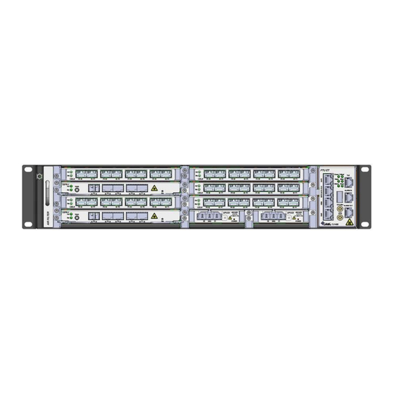
Page 99: Figure 53: Tj1400-7 Expansion Chassis
DPU8 or DPU18 (either single or redundant) inserted into the PSU slots, S105 and S106 of the chassis. The following figure shows TJ1400-7 expansion chassis on a TJ1400 system. Figure 53: TJ1400-7 expansion chassis Note: The TJ1400-7 expansion chassis will be shipped as plugged into the base chassis. ©Tejas Networks Ltd. -
Page 100: Table 56: Tj1400-7 Expansion Chassis Specifications
The FTU30P in TJ1400 (Expansion chassis) supports six fans. Alarm will be raised in case of over temperature and fan fail. The functional features of FTU30P are as follows: • Supports six fans • Fan speed monitoring and control through software, based on the temperature sensed ©Tejas Networks Ltd. -
Page 101: Figure 54: Tj1400-7 Expansion Chassis Ftu30P Card - Front Panel
The front panel of FTU30P has a bi-color LED to indicate the FAN status.The following table describes the LED color indications on FTU30P. Table 58: TJ1400-7 expansion chassis FTU30P - LED indications and their status Color Status Green Fan active Fan fail Amber Power on ©Tejas Networks Ltd. -
Page 102: Figure 55: Tj1400-7 Expansion Chassis Dpu8 Card - Front Panel
• Green will blink when the card goes down because of input voltage protection. Red and Red and green will blink alternatively if card goes for over Green temperature protection. Without redundant power supply in the system ©Tejas Networks Ltd. - Page 103 Green • Card is working fine. • Green will blink when the card goes down because of input voltage protection. Red and LED will be off in over temperature protection. green Blank If input is not present. ©Tejas Networks Ltd.
-
Page 104: Table 60: Tj1400-7 Expansion Chassis Dpu8 - Operational Specifications
IEC 60950-1 /EN 60950-1 • UL 62368-1 • UL 60950-1 • In-rush Current limiting as per ETSI EN 300 132-2 • ETSI EN 300 019 Part 1-1 • QM333 Hold-up time (Interruption) 2ms at –54V and above ©Tejas Networks Ltd. - Page 105 • Output Short-Circuit (Latched Protection) • Output Over-Current (26A ± 2A, Latched Protection) • Output Over-Voltage (13.6V ± 0.6V, Latched Protection) • Input Reverse Polarity (Continuous) • Input Under/Over voltage (Auto Retry Mode) • Non-latching thermal shutdown ©Tejas Networks Ltd.
-
Page 106: Figure 56: Tj1400-7 Expansion Chassis Dpu18 - Front Panel
Output voltage out of range. • Red will blink if card goes for over current protection. Green • Card is working fine. • Green will blink when the card goes down because of input voltage protection. Blank Input is not present. ©Tejas Networks Ltd. -
Page 107: Table 62: Tj1400-7 Expansion Chassis Dpu18 - Operational Specifications
IEC 60950-1 /EN 60950-1 • UL 62368-1 • UL 60950-1 • In-rush Current limiting as per ETSI EN 300 132-2 • ETSI EN 300 019 Part 1-1 • QM333 Hold-up time (Interruption) 0.5ms at –54V and above ©Tejas Networks Ltd. -
Page 108: Figure 57: Tj1400 Type-5Sep- Slot Id
A diagrammatic representation of the slot allotment on TJ1400 Type-5SEP is shown in the following figure. Figure 57: TJ1400 Type-5SEP- Slot ID Note: Ensure that all unused slots (I/O or Tributary side) are covered with appropriate fillers. ©Tejas Networks Ltd. -
Page 109: Table 63: Tj1400 Type 5Sep - Slot Distribution
Note: PDH cards (ST63E1 and ST6E3), SDH card (SOT18) and Ethernet card (CEL-1 and CEL-5) can be used in TJ1400 Type-5SEP system as normal tributary card without any protection. In such scenario, fill the empty IO and WP slots with appropriate filler panels. ©Tejas Networks Ltd. - Page 110 TJ1400 Product Family Hardware Description Guide v5.5 7.5 Cards overview The following are the data interface cards supported in the TJ1400-7 expansion chassis. • CEL-1 • CEL-5 • SOT18 • ST63E1 • ST6E3 • S63EWP • S63EIO • S12E3WP • S12E3IO ©Tejas Networks Ltd.
-
Page 111: Figure 58: Tj1400-13 System - Front Panel
The line cards support GPON interfaces of 2.5/1.25G, Ethernet and data interfaces of 10 Gigabit and 1 Gigabit Ethernet interfaces. The following figure shows the front panel of TJ1400-13 system. Figure 58: TJ1400-13 system - Front panel ©Tejas Networks Ltd. -
Page 112: Table 64: Tj1400-13 System Specifications
(FRU). TJ1400-13 consists of two FTU slots. Each FTU holds two fans. The system supports redundant configuration of fans. In case of single fan failure, the system will work up to 40°C temperature with CEF8-1 and up to 50°C with CEF8-1 ET. ©Tejas Networks Ltd. -
Page 113: Figure 59: Tj1400-13 Ftu - Front Panel
FTU is shown in the following figure. Figure 59: TJ1400-13 FTU - Front panel Card specifications The following table provides the specification of FTU card. Table 65: TJ1400-13 FTU - Card specifications Specification Range MTBF 68.7 years Input Voltage Power consumption 60W (typical) ©Tejas Networks Ltd. -
Page 114: Power Supply Unit - Dpu1250
Dynamic response 600mV (50% to 100% Load step) Efficiency 92.5% at 48V input voltage and 75A load Fuse for input current 60A slow blow fuse Recovery: –38V ± 2V Under voltage protection • • Shutdown: –36V ± 2V ©Tejas Networks Ltd. - Page 115 Over-temperature (Auto-recovery) • Output Short-Circuit (Hiccup Mode) • Output over-current limiting (125%) • Output over-voltage (13.6± 0.6V Latched Mode) • Input reverse polarity protection • Input under-voltage (Auto Retry Mode) • Non-latching thermal shutdown • Input over voltage ©Tejas Networks Ltd.
-
Page 116: Visual Indicator Details
Red and green will blink alternatively if card is in over temperature protection state. Blank If input is not present. 8.4 Slot allotment and bandwidth allocation TJ1400 Type-13SR chassis slot numbering is shown in the following figure. Figure 61: TJ1400-13 - Slot allotment ©Tejas Networks Ltd. -
Page 117: Table 68: Tj1400-13 Slot Bandwidth Allocation With Cef8-1/Cef8-1 Et
Card population rule. Table 68: TJ1400-13 slot bandwidth allocation with CEF8-1/CEF8-1 ET Slot Number Bandwidth per Slot 1, 2, 5, 6, 8, 9, 12, 13 3, 4 Note: Slot number 7 is for future use. ©Tejas Networks Ltd. -
Page 118: Cards Overview
TJ1400-13. The OAM interface provides static user interfaces and visual indications for managing operations, administration and maintenance of the system. The following figure shows the front panel of the OAM card. Figure 62: TJ1400-13 OAM- Front panel ©Tejas Networks Ltd. -
Page 119: Table 69: Tj1400-13 Oam Card Specifications
Card mis-match: Node has already configured the slot Amber Amber with some other card. Card failed during boot up. Amber Card failed while in-service. Green Hard Reset: All devices reset, FPGAs cleared and Amber Amber reprogrammed. Goes to initializing state next. ©Tejas Networks Ltd. -
Page 120: Table 71: Tj1400-13 Oam - Alarm Leds Indications
Alarm-Out: The alarm outputs can be used to trigger the operation of external • equipment, such as a generator, fan or audible alarm. The alarm outputs are caused by alarms detected by the node. The alarm-out is classified as minor, ©Tejas Networks Ltd. -
Page 121: Table 72: Tj1400-13 - Oam(Nms) Led Status And Their Significance
Table 73: TJ1400-13 port matrix with CEF8-1-i13 Attribute Support System switching capacity Up to 260Gbps Maximum number of 10GE ports Up to 10 Maximum number of 1GE ports Up to 74 Maximum GPON ports Up to 64 ©Tejas Networks Ltd. - Page 122 TJ1400 Product Family Hardware Description Guide v5.5 This page is intentionally left blank ©Tejas Networks Ltd.
-
Page 123: Tj1400-18
Note: The TJ1400-18 system automatically shuts down when the temperature of the system exceeds the threshold limit and also recovers once the temperature is within the limit. Figure 63: TJ1400-18 system - Front panel ©Tejas Networks Ltd. -
Page 124: System Specifications
40 V to 60 V DC Environmental Operating without air baffles 0° C to 50° C Specifications temperature range with air baffles 0° C to 50° C Relative humidity 5% to 95% RH Rated speed per fan Minimum: 4500 Specification Maximum: 14500 ©Tejas Networks Ltd. -
Page 125: Fan Tray Unit - Ftu
Detects presence of other FTUs in the chassis. In absence of any FTU from the chassis, the other FTU present in the chassis will run at full speed in compensation. Front panel Following figure shows the front panel of FTU. Figure 64: TJ1400-18 FTU - Front panel ©Tejas Networks Ltd. -
Page 126: Power Supply Unit - Dpu2500
9.3 Power supply unit - DPU2500 Power Supply Unit (PSU) DPU2500 supports load sharing on redundancy basis with dual feeds, if one PSU fails then the other PSU will be the active load driver and provides a ©Tejas Networks Ltd. -
Page 127: Figure 65: Tj1400-18 Dpu2500 - Front Panel
Steady Indicates that the 12 V Output is out of the tolerance level. Blinking Indicates abnormal output current. Indicates absence of Output voltage, that is, no power to the node. Red and Blinking Over temperature protection Green ©Tejas Networks Ltd. -
Page 128: Operational Specifications
ETSI EN 300 386 • IEC 62368-1 / EN 62368-1 • IEC 60950-1 /EN 60950-1 • UL 62368-1 • UL 60950-1 • In-rush Current limiting as per ETSI EN 300 132-2 • ETSI EN 300 019 Part 1-1 • QM333 ©Tejas Networks Ltd. - Page 129 Output Over-Current (125%) • Output Over-Voltage (13.6 ± 0.6 V Latched Mode) • Input Reverse Polarity • Input Under-voltage • Input Over-voltage Power Interface Input connector: 3 position terminal block header Molex connector, 85.0 A (Maximum per Contact). ©Tejas Networks Ltd.
-
Page 130: Slot Allotment And Bandwidth Allocation
Table 79: TJ1400-18 slot bandwidth allocation with CSC1 Slot Number Bandwidth per Slot 11, 13, 15, 16, 17, 18 1, 3, 7, 8, 9, 10 2, 4, 12, 14 140G Note: Slots 4 and 14 also support 2*100G and 4*10G bandwidth. ©Tejas Networks Ltd. -
Page 131: Cards Overview
The alarm input connects external triggers for events such as an open door or a high temperature in the shelf, to the Alarm In port on the OAM card. If an event occurs, a trigger connected to the external alarm input gets activated and the node raises an environmental alarm. ©Tejas Networks Ltd. - Page 132 1PPS interface is a synchronization interface to synchronize the node with GPS Hz clock. 9.7.1.5 10MHz port One Mini SMB receptacle with no LED indication. 50 ohm impedance. 10 MHz interface is a synchronization interface to synchronize the node with GPS 10 MHz clock. ©Tejas Networks Ltd.
-
Page 133: Table 80: Tj1400-18 Oam - Card Specifications
The OAM card has multiple LEDs on the front panel to indicate the card status, port status, link status or status of alarm reporting. The OAM has a status LED to indicate the status of the card and an active LED to ©Tejas Networks Ltd. -
Page 134: Table 81: Tj1400-18 Oam - Status And Active Led Indication
There are three alarm visual indications on the front panel of OAM card, namely, Critical, Major, and Minor. Table 83: TJ1400-18 OAM - Alarms LEDs indications Label Color Description Critical Critical alarm detected by node. Default state. No critical alarm detected. ©Tejas Networks Ltd. -
Page 135: Table 84: Tj1400 -18 Port Matrix With Csc1
Full Duplex. Maximum number of 10GE Up to 77 ports Maximum number of 1GE Up to 148 ports Maximum number of 100 Up to 128 Mbps ports Maximum GPON ports Up to 128 ©Tejas Networks Ltd. - Page 136 TJ1400 Product Family Hardware Description Guide v5.5 This page is intentionally left blank ©Tejas Networks Ltd.
-
Page 137: Card Population Rule
1, 2, 5, 6, 8, 9, 12, See Note 3 16x2.5G PON 2, 6, 9, 13 SOT18 1, 3, 5, 6, 7 ST63E1 1, 3, 5, 6, 7 CEM1 1, 3, 5, 6, 7 See Note 9 ©Tejas Networks Ltd. - Page 138 2, 4, 12 and 14 CEL12 1 to 4 and 7 to 18 See Note 4 8x2.5G PON 1 to 4 and 7 to 18 See Note 5 16x2.5G PON 1 to 4 and 7 to 18 See Note 5 ©Tejas Networks Ltd.
- Page 139 1, 3, 5, 6 Expansion Chassis: 107, 108, 109, 110, See Note 6 XA14OT5 2, 4 ST63E1 1, 3, 5, 6 ST6E3 1, 3, 5, 6 SOT18 1, 3, 5, 6 Expansion Chassis: 107, 108, 109, 110, See Note 6 ©Tejas Networks Ltd.
- Page 140 S12E3IO Expansion Chassis: 102, 104 CEF-1 1, 3, 5, 6, 7 CEF1-9P 1, 3, 5, 6 CEF-4 1, 3 CEL-1 1, 3, 5, 6, 7 CEL-5 1, 3, 5, 6, 7 CEL6 1, 3, 5, 6, 7 ©Tejas Networks Ltd.
- Page 141 S12E3IO Expansion Chassis: 102, 104 CEF-1 1, 3, 5, 6, 7 CEF1-9P 1, 3, 5, 6 CEF-4 1, 3 CEL-1 1, 3, 5, 6, 7 CEL-5 1, 3, 5, 6, 7 CEL6 1, 3, 5, 6, 7 ©Tejas Networks Ltd.
- Page 142 S12E3IO Expansion Chassis: 102, 104 CEF-1 1, 3, 5, 6, 7 CEF1-9P 1, 3, 5, 6 CEF-4 1, 3 CEL-1 1, 3, 5, 6, 7 CEL-5 1, 3, 5, 6, 7 CEL6 1, 3, 5, 6, 7 ©Tejas Networks Ltd.
- Page 143 Note 5: Maximum 12 8x2.5G-PON cards and 8 16x2.5G-PON cards are supported. Note 6: Port configuration depends on the bandwidth support on the slot. For details, refer Slot allotment on page 83. Note 7: Maximum 4 CEF-1 cards are supported. Note 8: Maximum 4 CEF1-9P cards are supported. ©Tejas Networks Ltd.
- Page 144 Note 11: When XA14ET and XA14OT5 cards are used, slot S7 is not supported. Therefore, slot S7 should be installed with tributary/cross-connect filler. Note 12: APU12 is supported with XA14ET/XA14OT5/XA10G as cross-connect card in the system. ©Tejas Networks Ltd.
-
Page 145: Controller And Switching Cards
Following figure shows the front panel of CEF4. Figure 68: CEF4 - Front panel Card specifications Table 86: CEF4 - Card specifications Specification Value MTBF 29.92 years Input voltage 12V ±10% Power consumption 80 Watt (maximum) Operating temperature range 0°C to 50°C ©Tejas Networks Ltd. -
Page 146: Table 87: Cef4 - Active And Status Leds Indications
Tx LED SFP present (Laser on) with Rx LOS Amber Green SFP present (Laser off) with Rx LOS Amber SFP present (Laser on) with no Rx LOS Green Green SFP present (Laser off) with no Rx LOS Green ©Tejas Networks Ltd. -
Page 147: Cef7G
DIAG interface provides a serial connection to node, where a user can launch a terminal session to log onto the Operating System. Note: The DIAG (diagnostic) interface is meant for use by authorized Tejas Networks personnel only. ©Tejas Networks Ltd. -
Page 148: Figure 69: Cef7G - Front Panel
(Steady) Hard Reset: All devices reset, FPGAs cleared and Amber Amber reprogrammed. Node goes to initializing state next. Soft Reset: Software is restarted, devices are re- Amber Amber initialized with provisioning. Node goes to initializing state next. ©Tejas Networks Ltd. -
Page 149: Cef7X
CEF7X - Normal temperature variant (operating temperature range is 0°C to +50°C). • CEF7X ET - Extended temperature variant (operating temperature range is –40°C to +65°C). Note: Except for the operating temperature range all the specifications mentioned remain same for both variants. ©Tejas Networks Ltd. -
Page 150: Figure 70: Cef7X - Front Panel
(Steady) Card in service: Initialization complete and card in Green (Steady) Green service. (Steady) Card mis-match: Node has already configured the Amber Amber slot with some other card. Card failed during boot up Amber ©Tejas Networks Ltd. -
Page 151: Table 95: Cef7X - Xfp Port Led Indications
Node goes to initializing state next. Following table describes XFP port LED status indications. Table 95: CEF7X - XFP Port LED indications State LED Color Admin down Admin up, link down Amber Admin up, link up Green Transmitter Laser Fault ©Tejas Networks Ltd. -
Page 152: Cef8-1
CEF8-1-i13 have 4GB DDR4 processor memory. • CEF8-1-i7 is a double-slot card and has a maximum switching capacity of 160Gbps. • CEF8-1 ET and CEF8-1-i13 are single-slot cards and have a maximum switching capacity of 260Gbps. Front panel ©Tejas Networks Ltd. -
Page 153: Figure 72: Cef8-1 - Front Panel
The following figure shows the front panel of the CEF8-1 ET card (Extended temperature variant). Figure 73: CEF8-1 ET - Front panel The following figure shows the front panel of the CEF8-1-i7 card (Industrial temperature variant). Figure 74: CEF8-1-i7 - Front panel ©Tejas Networks Ltd. -
Page 154: Figure 75: Cef8-1-I13 - Front Panel
The following figure shows the front panel of the CEF8-1-i13 card (Industrial temperature variant). Figure 75: CEF8-1-i13 - Front panel Note: The Reset button and the DIAG (diagnostic) interface are meant for use by authorized Tejas Networks personnel only. Card specifications Table 97: CEF8-1 - Card specifications Specifications... -
Page 155: Cef8-2
CEF8-2 card. Similarly, any additional 10GE ports can be supported using CEL13 card. • Supports tunable DWDM SFPs. Note: The Reset button and the DIAG (diagnostic) interface are meant for use by authorized Tejas Networks personnel only. ©Tejas Networks Ltd. -
Page 156: Figure 76: Cef8-2 - Front Panel
Goes to initializing state next. Redundant card: Secondary CEF8-2 card after Green (Steady) initialization. LED for optical interfaces (SFP+ and CFP2) indicates admin status of the port. Each port has two single color LEDs, Red and Green. ©Tejas Networks Ltd. -
Page 157: Table 102: Cef8-2 - Port Led Indications
Table 102: CEF8-2 - Port LED indications State Green LED Red LED Module absent Module present + LOS + with or without Tx enable Module present + no LOS + Tx disabled Blinks at 0.5Hz Module present + no LOS + Tx enabled ©Tejas Networks Ltd. -
Page 158: Csc1
Operating System. • USB: A USB 2.0 port can be used for copying files to/from USB flash drive. Note: The DIAG and USB ports are meant for use by authorized Tejas Networks personnel only. ©Tejas Networks Ltd. -
Page 159: Table 103: Csc1- Card Specifications
Card mis-match: Node has already configured the slot Amber Amber with some other card. Card failed during boot up. Amber Card failed while in-service. Green Hard Reset: All devices reset, cleared and Amber Amber reprogrammed. Goes to initializing state next. ©Tejas Networks Ltd. -
Page 160: Table 105: Csc1- Port Led Indications
SFP present (Laser off) with Rx LOS SFP present (Laser on) with no Rx LOS Green SFP present (Laser off) with no Rx LOS SFP missing (LOS detected), Laser On (attempted) SFP failed (whether provisioned, unprovisioned, LOS or no LOS) ©Tejas Networks Ltd. -
Page 161: Xa14Et
Digital Diagnostics: All diagnostic features of SFP optics, such as receive power measurement, back facet, laser bias, and temperature can be monitored. Front panel The following figure shows the front panel of XA14ET card. Figure 77: XA14ET - Front panel ©Tejas Networks Ltd. -
Page 162: Xa14Ot5
Power on state No receive power Green Receive power OK 12.2 XA14OT5 The XA14OT5 is the cross-connect and aggregate card that consists of the cross-connect sub-system and the timing sub-system. The system provides for redundancy on the XA14OT5 card. ©Tejas Networks Ltd. -
Page 163: Figure 78: Xa14Ot5 - Front Panel
Following figure shows the front panel of the XA14OT5 card. Figure 78: XA14OT5 - Front panel Card specifications Table 109: XA140T5 - Card specifications Specification Range Input Voltage 12V± 5% Power consumption Operating temperature range 0°C to 50°C ©Tejas Networks Ltd. -
Page 164: Table 110: Xa140T5 - Status And Active Leds Indications
Amber Amber reprogrammed. Goes to initializing state next. Table 111: XA140T5 - Transmit and Receive Laser status Color Status Power on state Laser Off Green Laser On Power on state No receive power Green Receive power OK ©Tejas Networks Ltd. -
Page 165: Xa10G
The following figure shows the front panel view of XA10G card: Figure 79: XA10G Card - Front panel Card specifications Table 112: XA10G - Card specifications Specification Value Input voltage 12V± 5% Power consumption 25W maximum Operating temperature range 0°C to 50°C ©Tejas Networks Ltd. -
Page 166: Xa20G
XA20G is a cross-connect and aggregate card that consists of the cross-connect sub- system and the timing sub-system. The system provides redundancy on the XA20G card. Following are the functional features: • Supports 2xSTM-1/OC-3 on ports P1 and P2, 1xSTM-4/OC-12 on port P3, 1xSTM- 4/16/OC-12/48 on port P4. ©Tejas Networks Ltd. -
Page 167: Figure 80: Xa20G - Front Panel
Master. Card in Slave service: Initialization complete and card Green in service as Slave. Card mis-match: Node has already configured the slot Amber Amber with some other card. Card failed during boot up. Amber ©Tejas Networks Ltd. -
Page 168: Xa60G
Supports reset of processor with a reset switch. • Supports DIAG-audio interface. • Supports craft (MI/F1) interface. • Digital Diagnostics: All diagnostic features of SFP optics, such as Receive power measurement, back facet, laser bias, and temperature, can be monitored. ©Tejas Networks Ltd. -
Page 169: Figure 81: Xa60G - Front Panel
Slave) Card mis-match Amber Amber Amber Card fails during boot-up. Amber Amber Card Oos (admin Down): Card out of service and failed. Card Fail: Card failed while in-service Green (this May happen with the only master card). ©Tejas Networks Ltd. -
Page 170: Xa100G
Redundant and non-redundant configurations. • Diagnostics port at the front using audio jack connector. • Digital Diagnostics: All diagnostic features of SFP optics, such as Receive power measurement, back facet, laser bias, and temperature, can be monitored. ©Tejas Networks Ltd. -
Page 171: Figure 82: Xa100G Card - Front Panel
The front panel view of XA100G card is shown below. Figure 82: XA100G Card - Front panel Card specifications Table 122: XA100G - Card specifications Specification Range Input Voltage 12 V ±5% Power consumption 90 W Maximum Operating temperature range 0°C to 50°C ©Tejas Networks Ltd. -
Page 172: Table 123: Xa100G - Active And Status Leds Indications
Green SFP present (Laser off) with Rx LOS Amber SFP present (Laser on) with no Rx LOS Green Green SFP present (Laser off) with no Rx LOS Green SFP missing (LOS detected), Laser On Amber Green (attempted) ©Tejas Networks Ltd. - Page 173 Transmitter LED Status Status SFP present (Laser on) with Rx LOS Amber Green SFP missing (LOS masked since SFP missing Amber and set to Admin_down), Laser Off (attempted) SFP failed (whether provisioned, unprovisioned, LOS or no LOS) ©Tejas Networks Ltd.
- Page 174 TJ1400 Product Family Hardware Description Guide v5.5 This page is intentionally left blank ©Tejas Networks Ltd.
-
Page 175: 8X2.5G Pon
• 8x2.5G-PON - Normal temperature variant (operating temperature range is 0°C to +50°C). • 8x2.5G-PON ET - Extended temperature variant (operating temperature range is –40°C to +65°C). Note: Except for the operating temperature range all the specifications mentioned remain same for both variants. ©Tejas Networks Ltd. -
Page 176: Figure 83: 8X2.5G-Pon - Front Panel
Card in service: Initialization complete and card in Green (Steady) Green service. (Steady) Card mis-match: Node has already configured the Amber Amber slot with some other card. Card failed during boot up. Amber Card failed while in-service. Green (Steady) ©Tejas Networks Ltd. -
Page 177: Table 127: 8X2.5G Pon Port Led Indications
LOS) Supported Laser type Laser Laser type CLASS B+ GPON OLT 2488/1244 MBPS DS/US DFB/APD TRANSVR 3.3V 2X10SFP (SM, P2MPOLT, 20KM SC-TYPE) CLASS C + GPON OLT 2488/1244 MBPS DS/US DFB/APD TRANSVR 3.3V 2X10SFP CLASS C ©Tejas Networks Ltd. -
Page 178: 16X2.5G Pon
Operating System. Note: The DIAG (diagnostic) interface is meant for use by authorized Tejas Networks personnel only. Front panel Following figure shows the front panel of 16x2.5G-PON card. Figure 85: 16x2.5G-PON - Front panel ©Tejas Networks Ltd. -
Page 179: Table 128: 16X2.5G-Pon - Card Specifications
Tx LED SFP present (Laser on) with Rx LOS. Amber Green SFP present (Laser off) with Rx LOS. Amber SFP present (Laser on) with no Rx LOS. Green Green SFP present (Laser off) with no Rx LOS. Amber ©Tejas Networks Ltd. -
Page 180: Cef-1
• DIAG interface provides a serial connection to node using which a user can launch a terminal session to log onto the Operating System. Note: The DIAG (diagnostic) interface is meant for use by authorized Tejas Networks personnel only. ©Tejas Networks Ltd. -
Page 181: Figure 86: Cef-1 - Front Panel
Each optical port has LED to indicate the admin status of the port. Table 133: CEF-1 - Optical interface LED indication LED Color Status Admin down. Amber Admin Up, Link Down. Green Admin Up, Link Up. Transmitter Laser Fault. ©Tejas Networks Ltd. -
Page 182: Cef1-9P
Higher order and lower order virtual concatenation. Front panel Following figure shows the front panel of CEF1-9P card. Figure 87: CEF1-9P - Front panel Card specifications Table 135: CEF1-9P - Card specifications Specification Range Input voltage 12V± 10% Power consumption 30W maximum ©Tejas Networks Ltd. -
Page 183: Cel-1
Link is up, No Activity. Green Blinking Link is up, Activity present. 13.5 CEL-1 CEL-1 card supports 2xGE (Optical, 1000Mbps) optical interfaces on ports P5 and P6. Supports 1x10/100 Base-Tx/1000 Base-T interface on port P4 and 3x10/100 Base-Tx ©Tejas Networks Ltd. -
Page 184: Figure 88: Cel-1 - Front Panel
Card mis-match: Node has already configured the Amber Amber slot with some other card. Card Admin down: Initialization complete and card in Green Amber out-of-service state (and not failed). Card fails during boot up. Amber Card failed while in-service. Green (Steady) ©Tejas Networks Ltd. -
Page 185: Table 141: Cel-1 - Sfp Port Led Indications
Table 142: CEL-1 - Electrical interface LED status LED Color Status Green Amber Admin Down Or Admin Up, Link is down. Admin Up, Link Up, No Activity on Link. Blinking Admin Up, Link Up, Activity present on Link. ©Tejas Networks Ltd. -
Page 186: Cel-5
Card mis-match: Node has already configured the Amber Amber slot with some other card. Card Admin down: Initialization complete and circuit Green Amber pack in out-of-service state (and not failed). Card failed during boot up Amber Card failed while in-service Green (Steady) ©Tejas Networks Ltd. -
Page 187: Cel6
CEL6 card has front panel ports of 8x1000Base-X capacity. Ports P1 to P8 are SFP interfaces. CEL6 card is used as port extender to controller and switching cards. Front panel Following figure shows the front panel of CEL6. Figure 90: CEL6 - Front panel ©Tejas Networks Ltd. -
Page 188: Table 147: Cel6 - Card Specifications
Table 149: CEL6 - SFP port LED indications Condition Green SFP Present + Tx Enable + No Tx Fault + No LOS. SFP Present + Tx Enable + Tx Fault + With or without Blink LOS. LOS + No Tx Fault. Any other state. ©Tejas Networks Ltd. -
Page 189: Cel10
Following figure shows the front panel of CEL10. Figure 91: CEL10 - Front panel Card specifications Table 150: CEL10 - Card specifications Specifications Value MTBF 71 years Input voltage Power consumption 150W maximum Operating temperature range 0°C to 50°C ©Tejas Networks Ltd. -
Page 190: Table 151: Cel10-Slot Dependency
5-5 to 5-8 availability of BM- should be disabled. 6-5 to 6-8 FPGA ports. will be disabled too. To use port 14-6 (100G) on this slot, ports 5-11 should be disabled. 6-11 will be disabled too. ©Tejas Networks Ltd. -
Page 191: Cel12
CEL12 is the Carrier Ethernet Line card supports eight 10GE/OTU2e ports. Following are the functional specifications: • Supports 10GBASE-SR, 10GBASE-LR, 10GBASE-ER and 10GBASE-ZR optics. • Supports an uplink bandwidth of 80G capacity. • Optical SFP+ ports use SFP+ optics with LC connector. • Supports tunable DWDM SFPs. ©Tejas Networks Ltd. -
Page 192: Figure 92: Cel12 - Front Panel
Card failed while in-service. Green Hard Reset: All devices reset, cleared and Amber Amber reprogrammed. Goes to initializing state next. Soft Reset: Software is restarted, devices are Green Green reinitialized with provisioning. Goes to initializing state next. ©Tejas Networks Ltd. -
Page 193: Cel13
Following figure shows the front panel of CEL13 card. Figure 93: CEL13 - Front panel Card specifications Table 157: CEL13 - Card specifications Specifications Value Input voltage Power consumption 40W maximum Operating temperature range –40°C to 65°C ©Tejas Networks Ltd. -
Page 194: Cem1
Any other state. 13.11 CEM1 CEM1, the Circuit Emulation card supports 8xSFP optical interfaces with OC-12 port capacity. CEM1 card supports the following functional features: • DS3 CEM and DS1 CEM. • supports STM-1/OC-3, STM-4/OC-12 and STM-16/OC-48 port capacities. ©Tejas Networks Ltd. -
Page 195: Figure 94: Cem1 - Front Panel
Following figure shows the front panel of CEM1 card. Figure 94: CEM1 - Front panel Card specifications Table 160: CEM1 - Card specifications Specification Range MTBF 55 years Input voltage 12 V Power consumption 83 Watt (maximum) ©Tejas Networks Ltd. -
Page 196: Sot18
Following are the port configurations: • Eight ports P1 to P8 with LC connectors operating at STM-1 line rate. • Ports P1 and P5 with LC connectors operating in STM-4 line rate. ©Tejas Networks Ltd. -
Page 197: Figure 95: Sot18 - Front Panel
Hard Reset: All devices reset, FPGAs cleared and Amber Amber reprogrammed. Goes to initializing state next. Note: Some long haul SFPs will not measure receive power beyond (–8.5dBm). Hence before connecting long haul lasers, check the receive power with the optical power meter. ©Tejas Networks Ltd. -
Page 198: St63E1
E1 interface is provided through LFH connector. Front panel Following figure shows the front panel of ST63E1 card. Figure 96: ST63E1 - Front panel Card specifications Table 166: ST63E1 - Card specifications Specification Range MTBF 66.83 years Input voltage 12V ± 5% ©Tejas Networks Ltd. -
Page 199: St63E1Cem
(one for each E1/DS1 1-32 and E1/DS1 33-63). • Supports TDM port to TDM port cross-connect between ST63E1CEM card and CEM1 card with OC-12 capacity configured in DS1 mode and transmux mode in same node. • Performance monitoring for errors and alarm conditions. ©Tejas Networks Ltd. -
Page 200: St6E3
ST6E3 card provides six E3/DS3 interfaces. E3/DS3 signals are fed through the SMB connectors. The functional features of ST6E3 card are as follows: • Transporting both framed and unframed E3/DS3 traffic. • Performance monitoring for errors and alarm conditions. ©Tejas Networks Ltd. -
Page 201: St24E3
ST24E3 supports 24 ports of E3/DS3/EC1 channels in 75-ohm configuration. The ST24E3 provides the following functional features: • Provides line interface to 24 E3 (34.368 Mbps) or DS3 (44.736 Mbps) or EC1 (51.84 Mbps) clients, selectable on a per port basis. The E3/DS3/EC1 interface is ©Tejas Networks Ltd. -
Page 202: Figure 99: St24E3 - Front Panel
Following figure shows the front panel of ST24E3 card. Figure 99: ST24E3 - Front panel Card specifications Table 172: ST24E3 - Card specifications Specification Value MTBF 18 years Input voltage 12V ± 5% Power consumption 77W maximum Operating temperature range –40°C to 65°C ©Tejas Networks Ltd. -
Page 203: S63Ewp
DS1 with 1:2 protection scheme, slots S108 and S109 (with S63EIO in S101, S102) are used as work slots and slot S107 is used as protect slot. The functional features of S63EWP card is as follows: • Supports 63 E1/DS1 ports • Supports live insertion and hot-swap capability ©Tejas Networks Ltd. -
Page 204: S63Eio
Goes to initializing state next 13.18 S63EIO S63EIO card is a 63 E1/DS1 protection IO card. The E1/DS1 ports from the line side interface are switched to either work or protect tributary card depending on the control ©Tejas Networks Ltd. -
Page 205: Figure 101: S63Eio - Front Panel
Visual Indicator Details The visual indicator on S63EIO card includes a single LED named Sts (Status). Table 177: S63IO - Status LED indications Color LED Status Status Amber Power on Green Card is active Hardware error Card is Off ©Tejas Networks Ltd. -
Page 206: S12E3Wp
Card State Status LED Active - Active - Work Card Protect Card Card initialization: State before the Amber card initialize is complete on card (Steady) insertion Card in service: Initialization complete Green Green and card in service (Steady) ©Tejas Networks Ltd. - Page 207 Amber configured the slot with some other card Card failed during boot up Amber Amber Card failed while in-service Green Hard Reset: All devices reset, FPGAs Amber Amber Amber cleared and reprogrammed. Goes to initializing state next ©Tejas Networks Ltd.
-
Page 208: S12E3Io
The front panel view of S12E3IO card is shown in the following figure. Figure 103: S12E3IO - Front panel Card specifications Table 180: S12E3IO - Card specifications Specification Range Input voltage 12V ±10% Power consumption 8W Maximum ©Tejas Networks Ltd. -
Page 209: Using The Filler Panels
Blocks Electro Magnetic Interference (EMI) that may interfere with other equipment. • Directs the flow of air through the chassis. • Arrests the entry of dust into the chassis. Note: Do not operate the system unless all cards, power modules, and filler panels are in place. ©Tejas Networks Ltd. - Page 210 TJ1400 Product Family Hardware Description Guide v5.5 This page is intentionally left blank ©Tejas Networks Ltd.
-
Page 211: Optical Interface Specifications
0.5 dBm –1 dBm –7 dBm Wavelength (nominal) 1310 nm 1550 nm 1550 nm Connector type Duplex LC Duplex LC Duplex LC Optical pluggable slot- SFP+ SFP+ SFP+ cage-packaging Fiber type Single mode Single mode Single mode ©Tejas Networks Ltd. -
Page 212: Cfp2 Line Side Module Optical Interface Specifications
1294 to 1310nm 1528.77 to 1566.72nm @ 50 GHz Tuning OSNR for BER 10e-15 14 dB with SD-FEC Chromatic dispersion ± 22000 ps/nm (~1200 Km of tolerance G.652 fiber) Connector type Fiber type Single mode Single mode ©Tejas Networks Ltd. -
Page 213: Gpon Optical Interface Specifications
S4.1/10Km L4.1/40Km L4.2/80Km Minimum output power –15 dBm –3 dBm –3 dBm Maximum output power –8 dBm +2 dBm +2 dBm Receiver sensitivity –28 dBm –28 dBm –28 dBm Receiver overload –8 dBm –8 dBm –8 dBm ©Tejas Networks Ltd. -
Page 214: Stm-16/Oc-48 Optical Interface Specifications
–26 dBm Receiver overload –1 dBm –8 dBm –1 dBm –10 dBm –9 dBm Wavelength 1310 nm 1550nm 1550nm 1310 nm 1550 nm (nominal) Connector type Fiber type Single Single Single Single mode Single mode mode mode mode ©Tejas Networks Ltd. -
Page 215: Pon Sfps
GPON OLT Class C+ SFP (Industrial grade) 999-AVC001237-E HiSense LTE3680P-BH+ GPON OLT Class C++ SFP (Commercial grade) 999-AVC001218-E HiSense LTE3680P-BC+2 GPON OLT QSFP28 (Commercial grade) 999-AVC001201-E Innolight Technology TR-FC85S-N00 Corp Source Photonics SQG-CE-SR-CDFA Gigalight GQS-MPO101-SR4CL 999-AVC001152-E Coherent FTLC9551SEPM Gigalight GQS-MPO111-SR4CL Source Photonics SPQ-CE-SR-CDFA ©Tejas Networks Ltd. - Page 216 TJ1400 Product Family Hardware Description Guide v5.5 This page is intentionally left blank ©Tejas Networks Ltd.
-
Page 217: Regulatory Standard Compliance
ETS 300 019-1-1, Class 1.2 Storage • ETS 300 019-1-2, Class 2.3 Transportation • ETS 300 019-1-3, Class 3.2 Operating stationary use • QM333 –Standard for Environmental Testing of Telecommunication Equipment. RoHS compliant Directive 2011/65/EU and Directive 2015/863/EU ©Tejas Networks Ltd. - Page 218 TJ1400 Product Family Hardware Description Guide v5.5 This page is intentionally left blank ©Tejas Networks Ltd.
-
Page 219: Acronyms
Light Emitting Diode Loss Of Signal Manufacturer Part Number Network Management System Operation, Administration and Management Optical Line Termination Optical Network Terminal Passive Optical Networks Packet Transmission Network Small Form-factor Pluggable Time of Day Tejas Part Number ©Tejas Networks Ltd. - Page 220 TJ1400 Product Family Hardware Description Guide v5.5 This page is intentionally left blank ©Tejas Networks Ltd.
Need help?
Do you have a question about the TJ400 Series and is the answer not in the manual?
Questions and answers