Table of Contents
Advertisement
Quick Links
Advertisement
Table of Contents

Related Manuals for UTICA BOILERS MAGB Series


Summary of Contents for UTICA BOILERS MAGB Series
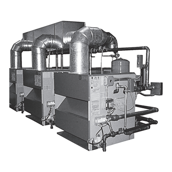
- Page 1 MAGB SERIES Gas Fired Modu-Pac Multiple Commercial Boiler System INSTALLATION, OPERATION & MAINTANANCE MANUAL Utica BOiLERS P.O. Box 4729 Utica, NY 13504-4729 37518701 , Rev. C [12/11] An ISO 9001-2000 Certified Company MEMBER: The Hydronics Institute...
-
Page 2: Table Of Contents
MAGB SERIES GAS FIRED BOILERS FOR FORCED HOT WATER INSTALLATION MANuAL AND OpERATING INSTRuCTIONS TABLE OF CONTENTS SAFETY SYMBOLS The following defined symbols are used throughout this Boiler Ratings & Capacities ........2 manual to notify the reader of potential hazards of vary- Typical Layouts For Gas Fired Systems ....4... -
Page 3: Boiler Ratings & Capacities
BOILER RATINGS & CApACITIES WARNING All installations of boilers and venting should be done only by a qualified expert and in accordance with the appropriate manual. Installing or venting a boiler or any other gas appliance with improper methods or materials may result in serious injury or death due to fire or to asphyxiation from poisonous gases such as carbon monoxide which is odorless and invisible. - Page 4 BOILER RATINGS & CApACITIES MaGB GaS FiRED BOiLER SERiES EnGinEERinG DiMEnSiOnaL Data net i=B=R Flue Outlet com- chimney Model Water Ratings Dia. & no. input Output Diameter number Vent Btuh Btuh & height Btuh** SQ. Ft. 8” 9” Dia. MAGB500 500,000 *410,000 356,500...
-
Page 5: Typical Layouts For Gas Fired Systems
TYpICAL LAYOuTS FOR GAS FIRED SYSTEMS 27" 31" 27" ACCESS ACCESS MIN. REAR "L" "D" FRONT "D" "L" FOR 1 BATTERY, (3 BOILERS PER BATTERY), IS 99 ⅞" FOR MAGB 750 AND 111 ½" FOR MAGB 900 "D" FOR 1 BATTERY, (3 BOILERS PER BATTERY), 1S 36 ⅝"... -
Page 6: Supply And Return Piping
SuppLY AND RETuRN pIpING INSTALLATION pROCEDuRE The installation must conform to the requirements of the WARNING authority having jurisdiction or, in the absence of such require- 1. Keep boiler area clear and free from combustible mate- ments, to the latest revision of the National Fuel Gas Code, rials, gasoline and other flammable vapors and liquids. -
Page 7: Ventilation And Combustion Air
INSTALLATION pROCEDuRE replacement, condensate trap, control replacement, etc.). FOR INSTALLATION ON NON-COMBUSTIBLE FLOORS ONLY *. The boiler must not be installed on carpeting. Minimum clear- LOCATE BOILER on level, solid base as near the chimney as ances to combustible construction are: possible and centrally located with respect to the heat distribu- TOP ...........18 IN. - Page 8 VENTILATION & COMBuSTION CONTINuED FIGuRE #1 FIGuRE #2 Ventilation of the boiler room must be adequate to provide suf- methods A or B. When ducts are used, they shall be of the same ficient air to properly support combustion per the latest revision cross sectional area as the free area of the area of the openings of the National Fuel Gas Code, ANSI Z223.1.
-
Page 9: Vent Installation
VENTILATION & COMBuSTION CONTINuED be assumed that wood louvers will have 20-25% free area and the sum of the areas of all vent connectors in the confined metal louvers and grilles will have 60-75% free area. Louvers space. and grilles should be fixed in the open position or interlocked In calculating free area using louvers, grilles or screens for the with the boiler so they are opened automatically during the above, consideration shall be given to their blocking effect. -
Page 10: Vent System Modification
VENT INSTALLATION FIGuRE #3 FIGuRE #4 LOCKNUT ACCEPTABLE VENT HARNESS INSTALLER DAMPER LOCATIONS CONN. HOOK-UP REFER TO DAMPER MANUFACTURER'S INSTALLATION INSTRUCTIONS FOR POSITION OF DAMPER CONTROL BOX DAMPER CHIMNEY MOTOR DAMPER INSTALLER UN-ACCEPTABLE CONN. HOOK-UP DAMPER LOCATIONS VENT DAMPER VENT OUTLET BOILERS HOT WATER HEATER... -
Page 11: Connecting Boilers With Refrigeration Systems
CONNECTING BOILERS WITH REFRIGERATION SYSTEMS figure 5 Connect supply and return piping as suggested in pipes. when the boiler is used in connection with refrigerated systems. When the boiler is connected to heating coils located in air The chilled medium MUST BE PIPED IN PARALLEL with the handling units where they may be exposed to refrigerated boiler. -
Page 12: Connecting Gas Service
CONNECTING GAS SERVICE Connect gas service from meter to control assembly in accor- Check all connections using a commercially available soap solu- dance with ANSI Z223.1 and local codes or utility. A ground tion made specifically for leak detection. joint union should be installed for easy removal of gas control WARNING for servicing. -
Page 13: Electrical Wiring
2. Install a fused disconnect switch between boiler and electrical panel at a convenient location. 3. The MAGB series requires 120 Volts to operate. Electrical wiring must conform with the National Electrical Code, ThIngs To AvoId When LocATIng TherMo- ANSI/NFPA No. - Page 14 ELECTRICAL WIRING CAUTION Label all wires prior to disconnection when servicing controls. Wiring errors can cause improper and dangerous operation. Verify proper operation after service. 24 VOLT GAS CONTROL WIRING WITH LIMIT CONTROL VR8300H VR8300H J-BOX J-BOX TRANSFORMER TRANSFORMER TR-2 TR-2 J-BOX J-BOX...
-
Page 15: Lighting Instructions
LIGHTING INSTRuCTIONS WARNING CAUTION If you do not follow these instructions exactly, a fire or Before lighting any type of pilot burner (standing or in- explosion may result causing property damage, personal termittent), make certain the hot water boiler and system injury or loss of life. -
Page 16: Normal Sequence Of Operation
LIGHTING INSTRuCTIONS LIGHTING INSTRuCTIONS FOR CONTINuOuS pILOT FIGuRE #9 STOP! Read the safety information at the beginning of these instructions. Set the thermostat to the lowest setting. Turn off all electric power to the appliance. Remove access panel and burner door. Figure Turn gas control knob clockwise to "OFF"... -
Page 17: General Instructions
GENERAL INSTRuCTIONS When the cleaning process is complete, restore the boiler compo- Before seasonal start-up, have a competent service agency check the nents to their original position. Use IS-808 GE silicone, available boiler for soot and scale in the flues, clean the burners and check the from a distributor, to seal around the flue collector and boiler cast- gas input rate to maintain high operating efficiency. - Page 18 GENERAL INSTRuCTIONS FIGuRE #11 BLOCKED VENT SAFETY SWITCH HOLD DOWN BOLT INTEGRAL DRAFT HOOD BLOCKED VENT SAFETY SWITCH BURNER DOOR BASE BURNERS MANIFOLD JACKET BASE PANEL ROLL-OUT SAFETY SWITCH ORIFICES GAS VALVE FIGuRE #13 FIGuRE #14 3/8” TO 1/2” IN FLAME IGNITION ELECTRODE BURNERS ORIFICES...
-
Page 19: Checking Gas Input Rates To Boiler
CHECKING GAS INpuT RATES TO BOILER FIGuRE #15 divide the input rate shown on the rating plate by the heating value of the gas obtained from the local gas company. This will determine the number of cubic feet HIGH LIMIT AND OPERATING CONTROL of gas required per hour. - Page 20 OpTIONAL CONTROLS & WIRING Wiring on ARGO AMB Control to Multiple MAGB Boilers FIGuRE #16 AMB-4 WATER SENSOR OUTSIDE SENSOR IF USING EXTERNAL DAY/NIGHT FEATURE CONNECT HERE (DRY CONTACT) IF USING REQ/ACK CONNECT HERE (TT/THERMOSTAT DRY CONTACT) TO PRIORITY IF USING (DRY CONTACT) Yellow Yellow...
-
Page 21: Magb Series Replacement Parts
MAGB SERIES REpLACEMENT pARTS BASE Item Item Description Part # Qty. Description Part # Qty. BURNER TUBE 1 1/2" - 250 GAS VALVE VR8200H - 50 - 300 24V LP VG00307 240005543 BURNER TUBE 1 1/2" - 300 GAS VALVE VR8304H4 - 175-300 SPARK NAT... - Page 22 MAGB SERIES REpLACEMENT pARTS JACKET itEM # DEScRiPtiOn PaRt # QtY. PANEL - TOP MAGB 250 31621506 PANEL - TOP MAGB 300 31621507 PANEL - LEFT MAGB 250 & 300 3162704 DRAFT DEFLECTOR MAGB 250 3162505 DRAFT DEFLECTOR MAGB 300...
- Page 23 MAGB SERIES REpLACEMENT pARTS hEat EXchanGER Fully assembled heat Exchangers 912000014 Heat Exchanger (6 Section) 912000013 Heat Exchanger (7 Section)
- Page 24 MAGB SERIES REpLACEMENT pARTS SPARK Spark Pilot Kit - Natural Gas 550001911 Spark Pilot Kit - LP/Propane 550001912 item Description Qty. PILOT BRACKET ASSEMBLY BRACKET SCREW SPARK CABLE PILOT TUBING, 1/8" x 24" Pilot Shield Natural Gas Q345A PILOT LP Q345A Pilot...
- Page 25 MAGB SERIES REpLACEMENT pARTS ELEctRicaL (nOtE: quantities are per module) itEM DEScRiPtiOn QtY. CABLE - DAMPER 60” 37413101 JCT BOX 4X4X1-1/2 EF-013.01 ELEC 4”X4” COVER/TERM STRIP EF04401 WIRE ASSY ROLLOUT/SPILL SWITCH 28” 37513301 HARNESS IGNITION TO GAS VALVE 37413602 PILOT IGNITION CABLE 30” (FOR SPARK ONLY)
- Page 26 MAGB SERIES REpLACEMENT pARTS PiPinG (nOtE: quantities are per module) ITEM DESCRIPTION QTY. PIPE - NPL 1.1/2X4.1/2 NPT PF-001.07 DRAIN - SHORT HW-016.03 PIPE - TEE 1.1/2X3/4X1.1/2 1510002 CONTROL L4006A (AQUASTAT) AQ-008.00 RELIEF VALVE 30# VR-001.01 WELL 3/4"X1.1/2" 1635001 GAUGE - THERALTIMETER 1260006 PIPE - NPL 3/4"X4"...
- Page 27 MAGB SERIES REpLACEMENT pARTS ROLLOUt & SPiLL SWitch Item # Description Part # Qty. TEMP. SENSOR BRACKET 109008518 CONTROL-FIXED TEMPERATURE THERMO (ROLLOUT SWITCH; ALSO AQ02101 USED AS SPILL SWITCH) SCREW - #6 X ¼ HEX HD HW06501 NOTE: The rollout switch is located at the burner manifold. The spill switch...
- Page 28 Utica BOiLERS 2201 Dwyer Avenue Utica NY 13501 web site: www.ecrinternational.com...
Need help?
Do you have a question about the MAGB Series and is the answer not in the manual?
Questions and answers