
Related Manuals for Huazheng HZZGF-Z


Summary of Contents for Huazheng HZZGF-Z
- Page 1 HZZGF-Z Intelligent DC High Voltage Generator Huazheng Electric Manufacturing (Baoding) Co., Ltd...
- Page 2 (0312) 6775656 to tell you to ser ve you at all times- Baoding Huazheng Elect ric Manufact uring Co. , Lt d. , our company will def initely make you satisf ied !
-
Page 3: Table Of Contents
Contents I. Product Overview ......................1 II. Main Features ........................1 III. Product Model Specification ..................2 IV. Main Technical Parameters Of The Product ..............3 V. Description Of Product Structure .................. 4 VI. Operation Steps Of The Instrument ................9 7. Other auxiliary functions ....................17 VIII. -
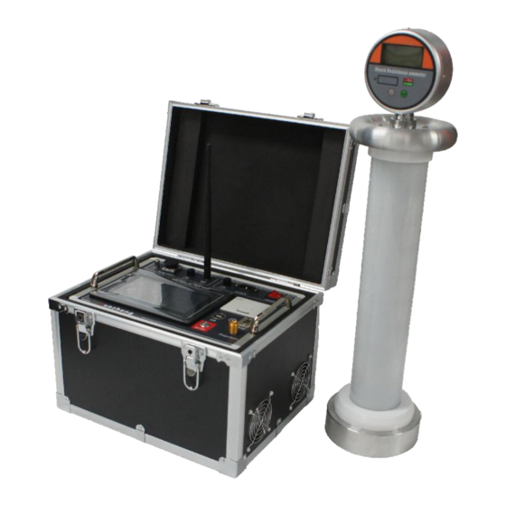
Page 4: Product Overview
I. Product Overview Intelligent DC high voltage generator, the main function of this product is to output negative DC high voltage voltage, with good output voltage stability and high precision, it is an indispensable product in preventive test and DC insulation withstand voltage test. -
Page 5: Product Model Specification
due to over-current. 11. Digital potentiometer is adopted, with 7 step voltage options: 60-160kV equipment (0.05 kV,0.1 kV ,0.2kV ,0.5 kV ,1.0 kV ,2.0 kV ,5.0 kV ) 200-350kV equipment (0.1 kV ,0.2 kV, 0.5 kV , 1.0 kV , 2.0 kV , 5.0 kV , 10 kV ) 12. -
Page 6: Main Technical Parameters Of The Product
250/2-5 250kV 380*275*275 1130*290*270 20kg 300/2-5 300kV 380*275*275 1300*290*270 22kg 350/2-5 350kV 380*275*275 1370*290*270 24kg Dimensions = pressure equalizing cover diameter (R) * insulation barrel diameter (r) * total height (H) IV. Main Technical Parameters Of The Product 1. Negative polarity output, 1.1 times of the maximum rated voltage. The output ripple factor is less than 0.5%. -
Page 7: Description Of Product Structure
V. Description Of Product Structure A. Control box panel description: 1. Color touch LCD display, all test information is displayed in Chinese by default, and Chinese and English can be switched in auxiliary functions. 2. Aviation socket: output to the high-voltage unit interface. When connecting the socket, please align the positioning pin first, then press the plug in, and tighten it clockwise. - Page 8 grounded. , to ensure the safety of the staff. 5. Insurance socket FU1: Inverter output fuse. 6. Insurance socket: main power input fuse. 7. Embedded micro-printer: It can print the data displayed on the current interface during work. 8. Main power switch: Avoid using the main switch as a high-voltage stop switch in normal use, except for emergency stop.
- Page 9 data transmission between the host and the anti-shock ammeter. B. High voltage unit: 1. The quick-installed aviation socket with aluminum base is used to connect with the control box. When installing the cable, first lay the high-voltage generator flat on the ground, align it with the plug positioning pin, press down and screw it clockwise, and do not shake it from side to side.
- Page 10 (Built-in antenna model) low-voltage level configuration, available when long-distance or outdoor tests are not required. 1. LCD display: current value display, unit display, polarity display, battery power display. Among them, the power indicator only has full power and no power status. The battery can be replaced when it shows no power.
- Page 11 the internal discharge resistance adopts the specification of 2M Ω /25W. The ground wire discharges directly, and at the initial discharge, the discharge rod approaches the high-voltage measurement end of the discharge test object from far to near. First enter the arc discharge through the air.
-
Page 12: Operation Steps Of The Instrument
(1) During the test, the human body must not touch the cable to prevent electric shock. (2) Try to avoid cable dragging, strong twisting, water immersion and large tensile force. (3) When the DC voltage is greater than 60kV, the composite insulation is used to improve the pressure bearing capacity. - Page 13 1. Wiring diagram (1) Connect the connecting wires of each cable, connect the grounding terminal of the control box to the grounding screw of the aluminum base at the bottom of the high voltage generator, and then connect to the earth and the ground of the tested product from the high voltage base.
- Page 14 protection, overload protection and FU1 fuse disconnection will not be able to output high voltage. For your safety and the normal use of the equipment, please be sure to check whether the grounding wire of the host shell is reliable! (7)...
- Page 15 Maximum voltage : the maximum voltage that the instrument can output, actually up to 1.1 times the rated voltage. Cannot be changed. Maximum current : the maximum current that the instrument can output. Cannot be changed. Protection voltage : higher than the test voltage setting, it can ensure that the maximum voltage does not exceed the voltage value of the test product.
- Page 16 The top of the interface displays the set overvoltage protection, test voltage, timing length and other parameter values. All start and stop buttons take effect after long pressing for 1 second, and other buttons are triggered by jogging, which is applicable to all interfaces. The boost and buck buttons are equivalent to the output adjustment mechanical knob in the lower right corner of the instrument panel, both of which can control the voltage output.
- Page 17 again. If it is a capacitive test object, artificial discharge must be carried out. ② MOA test interface--- The automatic test function of zinc oxide arrester is as follows Note: When performing the automatic test of the zinc oxide arrester, the test voltage setting should be 10% higher than the voltage at 1mA, and the overvoltage protection value should be at least 2KV higher than the test voltage.
- Page 18 On the right is the result of each step of the test. ④ Automatic test interface During the automatic test, the right side records the record of 1-10 minutes. 4. Introduction to the principle of capacitive test method...
- Page 19 When conducting capacitive test products such as cables, the equivalent circuit is an RC circuit, so there is a problem of attenuation and oscillation; reflected in the voltage, the voltage will fluctuate up and down until it stabilizes. This stabilization process is related to the equivalent capacitance of the test product.
-
Page 20: Other Auxiliary Functions
considered as 1 mA when the current is 950 uA to 1050 uA , and the voltage change at this time is about 0.02kV, which fully meets the requirements of the "Zinc Oxide Surge Arrester Test Standard" GB11032-89 . According to the voltage level of the tested product, the equipment corresponding to the voltage level is selected to make the test operation faster and more accurate. - Page 21 1. Data query 【Print】: Print the current record data, including the test date and time at that time. 【Export】: Export all the data to the U disk, use a random configured U disk, or a U disk with a format of FAT32 and a capacity of less than 32G. Insert the U disk and then select this menu to execute.
-
Page 22: Precautions For Use
3. The head is paired to configure the host and anti-shock current This function has been correctly configured one-to-one before leaving the factory, and only needs to be configured after replacing the anti-shock ammeter. Follow the setting steps to operate. VIII. - Page 23 1、 In order to ensure personal safety and equipment safety, the instrument should be well grounded and fully discharged after testing. 2、 The ground connection between the control box and the high voltage generator must be firm and reliable, and the ground screw at the bottom of the high voltage generator must be connected to the ground.
-
Page 24: Packing List
9、 The concave interface of the high-voltage equalizing cover has strong magnetism. When the high-end ammeter is connected to it, it should be approached slowly to avoid collision. 10、 In the capacitive sample test, due to the existence of RC charging oscillation and polarization absorption current phenomena, the voltage will enter a steady state after 1 minute.
Need help?
Do you have a question about the HZZGF-Z and is the answer not in the manual?
Questions and answers