Table of Contents
Advertisement
Quick Links
Advertisement
Table of Contents

Related Manuals for REFU REFUsol 25K-3T


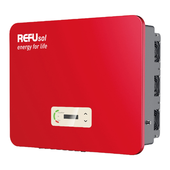
Summary of Contents for REFU REFUsol 25K-3T
-
Page 2: Table Of Contents
Table of Content Table of Content 1.1. Copyright declaration 1.2. Structure of the manual 1.3. Scope 1.4. Target group 1.5. Symbols used 2.1. Safety information 2.2. Symbols and signs 3.1. Product dimensions 3.2. Power grid types 3.3. Product dimensions 3.4. Labelling on the device 3.5. - Page 3 4.7. Installation of the inverter 5.1. Safety instructions 5.2. Electrical connection 5.3. Connections 5.4. Connecting the PE cables 5.5. Connecting the DC cables 5.6. Connecting the AC power cables 5.7. Communication ports 5.8. Energy meter connection 5.9. System monitoring 6.1. Safety test before commissioning 6.2.
-
Page 4: Copyright Declaration
1.1. Copyright declaration The copyright of this manual is owned by REFU Elektronik GmbH. It may not be copied – neither partially nor completely – by companies or individuals (including software, etc.) and must not be reproduced or... - Page 5 following symbol explanations carefully in order to prevent injury or property damage. DANGER Non-observance will result in death or serious injury. Follow the warnings in order to prevent death or serious injury! WARNING Non-observance may result in death or serious injury. Follow the warnings in order to prevent serious injury! CAUTION Non-observance may result in minor injury.
-
Page 6: Safety Information
2. Basic safety information NOTE If you have any questions or problems after reading the following information, please contact REFU Elektronik GmbH This chapter details the safety information pertaining to the installation and operation of the device. 2.1. Safety information... - Page 7 REFU Elektronik GmbH assumes no responsibility for the destruction of property or any injuries to personnel caused by improper usage. 2.1.2. Installation requirements Please install the inverter according to the information contained in the following section.
- Page 8 The labels must NOT be concealed by items and foreign objects (rags, boxes, devices, etc.); they must be regularly cleaned and kept clearly visible at all times. 2.1.5. Electrical connection Observe all applicable electrical regulations when working with the Solar inverter.
- Page 9 Should any repairs be required, please contact a local authorised service centre. The internal components of the inverter must NOT be opened without relevant authorisation. REFU Elektronik GmbH. assumes no responsibility for any resulting losses or defects.
-
Page 10: Symbols And Signs
2.2. Symbols and signs CAUTION Beware of burning hazards due to the hot housing! While the inverter is in operation, only touch the display and the buttons, as the housing can become hot. ATTENTION Implement earthing! The PV generator must be earthed in accordance with the requirements of the local power grid operator! For reasons of personal safety, we recommend that all PV module frames and inverters of the PV system are reliably... - Page 11 Symbol Description Residual voltage is present in the inverter! Before opening the inverter, you should wait five minutes to ensure that the capacitor has been fully discharged. Caution! Danger through electric shock Caution! Hot surface The product is compliant with EU guidelines Earthing point Please read the manual before installing the inverter Device degree of protection according to EN 60529...
-
Page 12: Product Dimensions
This chapter describes the product features, dimensions and efficiency levels. 3.1. Product dimensions The REFUsol 25K-3T/33K-3T/50K-4T is a grid-coupled PV inverter with up to two MPPTs which converts the direct current generated by PV systems into a three-phase alternating current and feeds it into the public power grid. -
Page 13: Product Dimensions
REFUsol 25K-3T/33K-3T/50K-4T are compatible with the following grid types: NOTE For the TT grid, voltage between N and PE should be less than 30 V. 3.3. Product dimensions All REFUsol 25K-3T/33K-3T/50K-4T have the following dimensions: H × W × D = 480 mm × 585 mm × 220 mm... -
Page 14: Labelling On The Device
NOTE REFUsol 25K-3T/33K-3T inverters support 6-channel PV string input. REFUsol 50K-4T and the HV models support 8-channel PV string input. 3.4. Labelling on the device... -
Page 15: Functional Features
Labelling must not be covered or removed! 3.5. Functional features The DC output generated by the PV generator is filtered by the input board before it reaches the power board. The input board also provides functions such as the detection of insulation impedance and the measurement of the DC current and voltage. -
Page 16: Efficiency Curve
Digital inputs (DRMs) The inverter can be switched on/off or the grid power can be controlled via the external control. Feeding of reactive power into the grid The inverter is capable of generating reactive power and can also feed it into the grid. The setting of the power factor (Cos Phi) can be controlled via the serial RS485 interface. - Page 17 Power efficiency curve (REFUsol 50K-4T) Rated power ratio vs. Grid voltage...
-
Page 18: Installation Information
4. Installation 4.1. Installation information DANGER Fire hazard Do NOT install the inverter on flammable material. Do NOT install the inverter in an area in which flammable or explosive material is stored. CAUTION Burning hazard Do NOT install the inverter in places where it can be accidentally touched. - Page 19 It is recommended that the packaging material should be removed within 24 hours before installing the inverter. 4.3.2. Checking the delivery scope Image Description Quantity Inverter REFUsol 25K-3T/33K- 3T/50K-4T Wall bracket AC waterproof cover M8*80 Hexagon screws PV+ metal pin...
-
Page 20: Tools
terminal insulation partition COM terminal R-type terminal (PE) R-type terminal (L1/L2/L3/N) Documents After unpacking the inverter, check that the delivery items are both intact and complete. In the event of any damage or missing components, contact the wholesaler. 4.4. Tools Prepare the tools required for the installation and the electrical connection. - Page 21 Tool Model Function Hammer drill Used to drill holes in the wall. Recommended drill: 60 mm Screwdriver Used to tighten and loosen screws when installing the AC power cable; to remove and install the screws of the AC terminal Removal tool Used remove terminal...
-
Page 22: Installation Location
Tool Model Function ESD gloves for the installer Safety goggles for the installer Anti-dust for the installer respiratory mask Socket wrench Used to install the expansion bolts Hammer Used to install the expansion bolts 4.5. Installation location Choose a suitable position for the installation of the inverter. Ensure that the following requirements have been fulfilled:... -
Page 23: Unpacking The Inverter
Minimum distances for individual REFUsol 25K-3T/33K-3T/50K-4T inverters: Minimum distances for several REFUsol 25K-3T/33K-3T/50K-4T inverters: 4.6. Unpacking the inverter... - Page 24 Open the packaging and have at least two people grip underneath the inverter at both sides.
-
Page 25: Installation Of The Inverter
Lift the inverter out of the packaging and move it to its installation position horizontally. ATTENTION Mechanical damage In order to prevent injuries and damage to the device, ensure that the inverter is kept balanced while it is being moved - it is very heavy. - Page 26 3. Place the inverter in the wall bracket. Secure the inverter to the wall bracket using the M6 hexagon screw.
-
Page 27: Safety Instructions
REFUsol 25K-3T/33K-3T/50K-4T. Read this section thoroughly and carefully before connecting the cables. DANGER Electrical voltage at the DC connections Ensure that the DC switch is OFF before establishing the electrical connection. The reason is that the electrical charge remains in the capacitor after the DC switch has been switched off. -
Page 28: Electrical Connection
The installation and maintenance of the inverter must be carried out by an electrician. The connected PV modules must be compliant with IEC 61730 class A. Max. PV Panel Model Max. AC output current REFUsol 25K-3T 42.4 A 3*50 A REFUsol 33K-3T 56.0 A REFUsol 50K-4T 4*50 A 83.3 A... -
Page 29: Connecting The Pe Cables
DC switch Venting valve PV input ports (positive) PV input ports (negative) WiFi/GPRS/Ethernet COM Port (RS485) AC output Fans 5.4. Connecting the PE cables Connect the inverter to the equipotential bonding bar by using the protective earth cable (PE) for grounding. ATTENTION Pole earthing not permissible! As the inverter is transformerless, the plus and minus poles of... -
Page 30: Connecting The Dc Cables
2. Crimp the cable to the ring terminal. Recommended OT terminal: OT- 3. Tighten the crimped ring terminal with the M6 screw by using a torque wrench of 5 to 7 Nm: 5.5. Connecting the DC cables NOTE Maximum tolerance voltage ≥ 1100 V... - Page 31 Please observe the recommended cable dimensions: Cu cable cross section: 2.5 ... 6 mm Cable outside diameter: 6 ... 9 mm Insert the positive and negative DC cables into the corresponding cable glands. Positive DC cable Negative DC cable 2. Use a crimping plier to crimp the DC cables.
- Page 32 CAUTION Danger of reverse polarity! Ensure that the polarity is correct before plugging into the DC connections! 3. Insert the crimped DC cables into the corresponding connector housing until you hear a “clicking” sound. Positive Negative 4. Verify the voltage level of the DC input with a multimeter and ensure that the polarity is correct.
-
Page 33: Connecting The Ac Power Cables
The AC disconnecting device must be easily accessible. NOTE The inverter REFUsol 25K-3T/33K-3T/50K-4T has a built-in AFI (univ. sensitive residual current protection). If an external AFI is required, we recommend an AFI type A or B RCD featuring a residual current of 100 mA or more. - Page 34 Dimensioning For correct installation, five-core outdoor cables should be used. To simplify the installation process, use flexible cables. The recommended cable specifications are listed in the following table. Model Cable cross-section Cu/Al Multi- AC circuit cable (mm core breaker REFUsol outdoor specifications cable...
- Page 35 You need to use five core outdoor cables, the recommended AC cable and residual current device (RCD) can be used as below table: If a RCD is required under local regulations, REFUsol recommends a type A or B RCD with sensitivity of 100 mA or higher. Where local electricity code requires an RCD with a lower leakage rating, the discharge current might result in nuisance tripping of the external RCD.
- Page 36 The AC output terminal is equipped with a high-current 5-core terminal block and a customized waterproof cover (IP65). Please follow below steps to connect the AC cable. 5.6.1. Installation instructions CAUTION Electrical voltage Ensure that the grid has been switched off before removing the AC connector.
-
Page 37: Communication Ports
This is supplied together with the copper terminals. 5.7. Communication ports The REFUsol 25K-3T/33K-3T/50K-4T inverters come with one of the following two COM ports and one USB port. COM port type I COM port type II... - Page 38 The USB port can be used to update the inverter's software version, or for connecting a WiFi-stick or Ethernet cable. 5.7.2. COM port Please follow below steps to install the COM cable according to the correct COM port (check the corresponding type A or B):...
- Page 39 Please refer to below table for the specific PIN assignments. Function Definition Note Inverter monitoring RS485 A1-1 RS485 Signal+ and system control RS485 A1-2 RS485 Signal + RS485 B1-1 RS485 Signal - RS485 B1-2 RS485 Signal - Energy meter port RS485 A2 RS485 Signal + RS485 B2...
- Page 40 5.7.3. Logic Interface: DRMs, Power Control and remote shutdown The DRM/Logic interface is used to control the inverter by external signals, usually provided from grid operators with ripple control receivers or other means. The logic interface inputs are defined according to different standard requirements.
- Page 41 Function Pin Definition Note Digital Input Grounding GND.S Signal GND DRMs/Logic DRM0 Remote Interface shutdown DRM1/5 0% power feed-in DI 5 DRM2/6 50% power feed- DI 6 DRM3/7 75% power feed- DI 7 DRM4/8 100% power DI 8 feed-in 5.7.3.2. Logic interface for VDE-AR-N 4105:2018-11 This function serves to control and/or limit the output power of the inverter.
-
Page 42: Energy Meter Connection
Function Definition Note Digital Input Grounding GND.S Signal GND DRMs/Logic DRM0 Remote Interface shutdown DRM1/5 0% power feed- DI 5 DRM2/6 30% power feed- DI 6 DRM3/7 60% power feed- DI 7 DRM4/8 100% power DI 8 feed-in 5.7.3.3. Remote Shutdown for EN50549-1:2019/VDE ARN 4105:2018-11 The inverter can be disconnected from the grid within 150 ms by an external signal. - Page 43 Inverter COM Port Function Energy Meter Pin RS485+ (A2) RS485- (B2) 5.8.1. Feed-in limitation function REFU Part Product Type...
-
Page 44: System Monitoring
NOTE The arrow of the CT’s must point to the grid 5.8.1.1. "Feed-in Limit" menu Feed-in Control Standard Mode. In case of a communication error with the SmartMeter, the inverter limits its output power to the setpoint. Hard Feed-in Control When the Hard Feed-in Control is activated, the inverter shuts down whenever the setpoint is exceeded... - Page 45 The REFUsol 25K-3T/33K-3T/50K-4T inverters provide various communication methods for the system monitoring: RS485 or WiFi stick (standard), GPRS or Ethernet stick (optional). 5.9.1. RS485 network You can connect RS485-linked devices to your PC via an RS485 USB adapter or connect them to a data logger.
- Page 46 REFUlog every 5 minutes. The sending interval can be changed with the configuration tool REFUset. To view the inverter data, open www.refu-log.com with your browser and login or register as a new user. You can use the activation code provided on the type label of the inverter to assign one or more inverter to a PV system.
- Page 47 Preparation: The WiFi stick is installed in accordance with the previous section and the REFUsol inverter must be in operation. Carry out the following steps in order to configure the WiFi stick: 1. Connect your PC or smartphone with the WiFi network of the WiFi stick.
- Page 48 The LEDs on the WiFi stick provide information regarding the status: Status Description NET: Communication On: Connection to server successful with the router Flashing (1 sec.): Connection to router successful Flashing (0.1 sec.): WPS mode active Off: No connection to router Communication Flashing (1 sec.): Communication with with inverter...
-
Page 49: Safety Test Before Commissioning
Ensure that you have selected the correct country code according to regional authority requirements, and consult a qualified electrician employees electrical safety authorities. REFU Elektronik GmbH responsible consequences of selecting the incorrect country code. selected country code influences the device grid monitoring. -
Page 50: Control Panel And Display Field
7. Operation of the device This chapter describes the LCD and LED displays of the REFUsol 25K- 3T/33K-3T/50K-4T 7.1. Control panel and display field 7.1.1. Buttons and display lights 7.1.1.1. Buttons Button Name Description Short press: Select previous menu item Long press: Exit menu or current interface Down Short Press: Select next menu item... -
Page 51: Standard Display
Normal (green) illuminates: “Normal” state flashes: “Wait” or “Check” state Alarm (red) illuminates: “Error” Ground Fault (red) illuminates: GFCI faulty 7.2. Standard display This shows a rolling display of the DC voltage/current (PV1), energy yields (today/total), grid voltage and current, as well as the status. 7.3. -
Page 52: Menu Structure
Repeated errors can lead to a permanent error Permanent which needs investigation and problem solving on site. 7.4. Menu structure Hold the down button to show the main menu. Main menu 1. Enter Settings See “Settings” 2. Event list See “Set country codes” 3. - Page 53 7. Set address Enter the Modbus address (when several inverters require simultaneous monitoring), standard: 01 8. Set input mode Either parallel mode or independent mode may be selected. 9. Set language Sets the display language of the inverter 10. Set Feed-in Limit Through this function...
- Page 54 Only for Italy NOTE The Autotest function is only applicable in Italy. Please contact REFU Elektronik GmbH for the specific steps. 7.4.1.1. Password Several settings require a password to be entered (the standard password is 0001). When entering the password, press briefly to change the figure and press and hold to confirm the current figure.
- Page 55 The event list is used to display the real time event recordings, including the total number of events and each specific ID no. and event time. The most recent events are listed at the top. 2. Event list 1. Current event 2.
-
Page 56: Software Update
Displays the current system time. 7.4.1.5. Software update The user can update the software via the USB flash drive. REFU Elektronik GmbH will provide the firmware update when it is required. 7.5. Software update Switch the DC and AC switches off and then remove the communication cover. -
Page 57: Error
8. Troubleshooting 8.1. Error This section contains information and procedures pertaining to the remedying of potential problems with the inverter. To carry out troubleshooting, proceed as follows: Check the warnings, error messages or error codes displayed on the screen of the inverter. If no error information is displayed on the screen, check whether the following requirements have been fulfilled: Has the inverter been set up in a clean, dry, well-ventilated area? - Page 58 Name Description Solution GridOVP The voltage of the If the alarm occurs power grid is too high occasionally, then the reason may be the power GridUVP The voltage of the grid. The inverter power grid is too low automatically returns to its normal operating state GridOFP The grid frequency is...
- Page 59 Name Description Solution operating state IpvUnbala Input current is not Check the setting of the symmetrical MPPT input mode (parallel mode/independent mode) PvConfigS Incorrect MPPT mode of the inverter and correct etWrong it as well if required. GFCIFault Earthing error If the error occurs occasionally, then external factors may be to blame.
- Page 60 Name Description Solution ltDCI measurement error HwADFau Grid voltage ltVGrid measurement error GFCIDevic GFCI measurement eFault error MChip_Fa Master chip error HwAuxPo Auxiliary voltage error werFault BusVoltZe Bus voltage roFault measurement error IacRmsUn The output current is balance not balanced BusUVP The DC bus voltage is If the configuration of the...
- Page 61 Name Description Solution if required. SwOCPIns The grid current is too Internal inverter error, high switch the DC switch OFF, wait 5 minutes and then switch the DC switch ON. Check whether the error has been rectified. If not, please contact the technical support department.
- Page 62 Name Description Solution tFault_GF GFCI between the master DSP and the slave DSP is not consistent SpiComm The SPI communication Lose between the master DSP and the slave DSP is faulty SciComm The SCI communication Lose between the control board and communications board is faulty RelayTest...
- Page 63 Name Description Solution unrectifiable error rectified. If not, please contact the technical Unrecover The grid current is support department. IacRmsUn unsymmetrical and has balance caused an unrectifiable error Unrecover The input current is IpvUnbala unsymmetrical and has caused an unrectifiable error Unrecover The bus voltage is...
- Page 64 Name Description Solution manual. Check whether the ambient temperature at the installation location exceeds the upper limit value. If so, improve the ventilation in order to reduce the temperature. OverFreq The inverter has derated The inverter automatically Derating itself due to the grid reduces the output power frequency being too when the frequency of the...
-
Page 65: Maintenance
Name Description Solution Lightning The overvoltage Check whether the device protectio protection has been is damaged and contact n alarm triggered the technician for assistance. Softwarev The the control board Contact the technical ersionisno and communications support department in tconsisten board software is not order to upgrade the consistent... - Page 66 soft cloth or a soft bristle brush. Do NOT clean the heat sink with water, corrosive chemicals, cleaning agents etc. 8.2.3. Fan maintenance Fans must be cleaned and maintained regularly for both performance and safety concerns. ATTENTION Regularly clean or maintain Broken or faulty fans may cause cooling issues, which may lead to limited heat dissipation and a lower working efficiency of the inverter.
- Page 67 Unscrew the screws at the fan position, unplug the terminals at the interface between the fan and the inverter and then remove the fan: Use a soft brush to clean the fan. In case of damage, ensure to replace it in time. Reinstall the inverter according to the above steps.
- Page 68 9. Technical data REFUsol 25K-3T REFUsol 33K-3T REFUsol 50K-4T Datasheet Input (DC) Recommended max. PV input 37500 49500 75000 power (Wp) Max. DC power for 25000 single MPPT (W) Number of MPP trackers Number of DC 2 for each MPPT inputs Max.
- Page 69 Rated grid voltage 3 / N / PE, 230 / 400 Grid voltage range 310 – 480 Vac (according to local standard) Rated frequency 50 Hz / 60 Hz Grid frequency 45 – 55 Hz / 55 – 65 Hz (according to local standard) range Active power 0 –...
- Page 70 Standard communication RS485 / USB, optional: Ethernet / WiFi mode General Data Ambient – 60 temperature range Self-consumption <3 at night (W) Topology Transformerless Degree of IP65 protection Allowable relative 0 – 100% humidity range Max. operating 4000 m altitude Noise <...
- Page 71 © REFU Elektronik GmbH The reproduction, distribution and utilization of this document as well as the communication of its contents to others without express authorization is prohibited. Offenders will be held liable for the payment of damages. All rights reserved in the event of the grant of a patent, utility model or design. The data specified is only used to describe the product and should not be interpreted as warranted characteristics in the legal sense.
Need help?
Do you have a question about the REFUsol 25K-3T and is the answer not in the manual?
Questions and answers