Advertisement
Quick Links
Unpack the 8256X cabinet. This cabi-
net
is sealed
at the factory;
do
not
attempt to take it apart or remove
the
back panel.
Turn the cabinet so the short side with-
out fiberglass lining is up; drill a hole in
the top, avoiding the diagnonal
brace.
This hole should be just large enough
to pass four wires through.
the second
loudspeaker as shown
in
Figure 2. Feed the attached
red and
black wires through the hole drilled in
the
top of the cabinet
(Step
2) or
through one of the bass reflex ports;
install the second
loudspeaker
in the
remaining baffle opening and secure it
with the eight screws packed with the
loudspeaker.
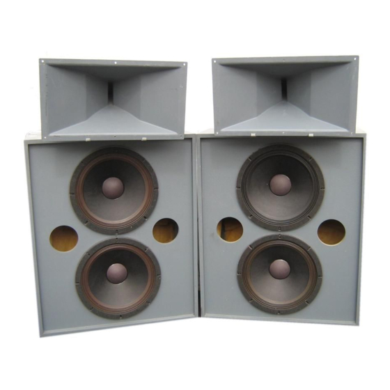
A6 SERIES
LOUDSPEAKER
SYSTEMS
12.
13.
14.
15.
16.
connectors
from
these
wires
and
replace them with those packed with
the 288-8K.
Place the N1285-8A on top of the cabi-
net, facing left or right; if the speaker
wires are routed through a port in the
baffle, put the N1285-8A
on the same
side.
Set the frequency switch of the N1285-
8A to 500 Hz or 800 Hz. Wire the N1285-
8A according to Figure 2.
If the
amplifier
to
be
used
cannot
safely drive a 5-ohm load, wire the sys-
tem
as shown
in Figure 3, using a
15067 autoformer.
If you wish to attach the N1285-8A
to
the cabinet, let the front panel of the
network
hang
over
the side
of the
cabinet; drill or punch twao pilot holes
and install two wood screws to secure
the network.
Decide how much power loss is accept-
able in the line between
the amplifier
and
the
loudspeaker;
select
a wire
gauge
according
to
Altec
Lansing
Technical
Letter
265A.
Attach
the
wires
to the
input
terminals
of the
7.
Lift the cabinet
upright and place it in
N1285-8A
network.
NOTE
the position it will occupy.
Do not drill this hole if the loud-
17.
Adjust the tilt of the HF horn for great-
speaker is to be installed behind
8. Unpack
the two brackets
and driver
est uniformity of direct sound
in the
the
screen
in a
motion
picture
cradle from the hardware kit.
Assemble
audience
area;
loosen
the
nuts
and
theatre.
them with two bolts, two lockwashers
raise
or lower
the driver
cradle
as
and two 7/16" nuts. See Figure 1. Set
necessary; retighten nuts.
The interconnecting
wires are packed
the assembly
on
top of the cabinet,
approximately centered with the driver
18.
Operate
the loudspeaker
and adjust
Locate the four longest wires (one red
cradle toward the rear of the cabinet.
the H.F. LEVEL control on the N1285-
wire, one green wire, two black wires).
8A until the best spectral balance is
9. Upack the 288-8K HF driver and the HF
achieved.
Unpack the two 3156 LF loudspeakers.
horn (MRII564,
MRII594,
or MRI15124).
Attach a green and black wire to the
Place
the gasket
packed
with
the
19. If there
is sufficient
front-to-back
terminals
of one
loudspeaker.
See
288-8K
around
its sound
exit hole;
clearance
around
the
loudspeaker,
Figure 2.
install the 288-8K on the horn, securing
adjust phasing of the drivers according
it with the three lockwashers and 9/16"
to Altec Lansing Applications
Note 9.
Lay
the
8256X
cabinet
on
its back
nuts provided.
This will require the front lip of the HF
panel. Mount one 3156 loudspeaker
in
horn to overhang the front edge of the
one
baffle
opening
of the
cabinet;
10.
Engage the lip flange of the horn in the
cabinet about 7".
attach
the
loudspeaker
with
eight
screws
packed
with the loudspeaker.
Note that the flange of the loudspeaker
is outside the cabinet, with the frame
and
magnet
structure
protruding
into
the cabinet.
Route the green and black wires of the
loudspeaker through the opposite baf-
fle opening;
attach the wires to the
second 3156 loudspeaker.
Also attach
red and black wires to the terminals of
11.
two ears of the mounting brackets and
swing the driver down into the cradle.
CAUTION
The magnet
will pull the cradle
toward the driver as it is lowered
into position.
Attach the short black and white wires
packed
with the N1285-8A
network
to
the terminals on the 288-8K. It will be
necessary to remove one pair of crimp
20.
21.
After locating the horn position, mark
location of the four holes in the mount-
ing brackets; drill or punch pilot holes
in the cabinet for the four wood screws
provided in the hardware kit.
If it becomes
necessary to replace the
diaphragm/voice coil assembly in the
288-8K driver, use a 23763 diaphragm;
follow
service
instructions
in Altec
Lansing publication 42-02-035593.
Specifications
and
components
subject
to
change
without
notice.
Overall
performance
will be maintained
or
improved.
ALTEC
42-02-035639
42-07-035639
REVISION
2
LITHO IN U.S.A. 1091-1.7M
ALTEC LANSING CORPORATION
LANSING
a MARK IV company
10500 W. Reno Ave., Oklahoma
City, OK 73126
Advertisement


Need help?
Do you have a question about the A6 Series and is the answer not in the manual?
Questions and answers