Table of Contents
Advertisement
Quick Links
Installation
Start-Up
Maintenance
Parts
Warranty
For Residential and Commercial Use
MSSU-N* Models
*Models with an "A" Suffix have an Anode Rod
This manual must only be used by a qualified installer / service technician. Read all instructions in this manual before installing.
Perform steps in the given order. Failure to do so could result in substantial property damage, severe personal injury, or death.
California Proposition 65 Warning: This product contains chemicals known to the State of California to cause cancer, birth
defects, or other reproductive harm.
The manufacturer reserves the right to make product changes or updates without notice and will not be held liable for
typographical errors in literature.
The surfaces of these products contacted by potable (consumable) water contain less than 0.25% lead by weight as required
by the Safe Drinking Water Act, Section 1417.
NOTE TO CONSUMER: PLEASE KEEP ALL INSTRUCTIONS FOR FUTURE REFERENCE.
272 Duchaine Blvd.
New Bedford, MA 02745
U
L
MAX
T
R
A
®
Indirect Fired Water Heaters
www.htproducts.com
lp-733 Rev. 002 Rel. 002 Date 02.27.24
Advertisement
Table of Contents

Related Manuals for HTP SUPERSTOR ULTRA MAX MSSU-N Series


Summary of Contents for HTP SUPERSTOR ULTRA MAX MSSU-N Series
- Page 1 ® Indirect Fired Water Heaters Installation Start-Up Maintenance Parts Warranty For Residential and Commercial Use MSSU-N* Models *Models with an “A” Suffix have an Anode Rod This manual must only be used by a qualified installer / service technician. Read all instructions in this manual before installing. Perform steps in the given order.
-
Page 2: Table Of Contents
Table of Contents Part 1 - General Safety Information The following defined terms are used throughout this manual to A. When Servicing the Water Heating System bring attention to the presence of hazards of various risk levels or to B. Heater Water important product information. -
Page 3: Part 1 - General Safety Information
The equipment is permanently labeled to indicate that only additives Part 1 - General Safety Information recognized as safe by the FDA shall be used as the heat transfer medium. This water heater is approved for indoor installations only and is not intended for use as a pool heater. -
Page 4: Part 2 - Prepare The Water Heater
Part 2 - Prepare the Water Heater This water heater must not be located near flammable liquids such Remove all sides of the shipping crate to allow the heater to be moved as gasoline, butane, liquefied propane, adhesives, solvents, paint into its installation location. -
Page 5: Water Chemistry Requirements
*NOTE: To promote water heater service life, it is strongly B. Water Chemistry Requirements recommended to follow the maintenance procedures in this manual. C. Anode Rod Chemical imbalance of the water supply may affect efficiency This water heater may be equipped with an anode rod. Anode rods are and cause severe damage to the water heater and associated sacrificial components that counteract water chemistry to minimize or equipment. -
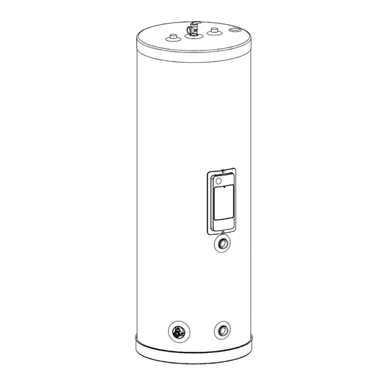
Page 6: Technical Specifications
D. Technical Specifications SUPERSTOR ULTRA MAX SERIES TOP VIEW - ALL MODELS THERMOSTAT ACCESS COVER BOILER IN THERMOSTAT ACCESS COVER BOILER OUT OUTLET INLET RELIEF VALVE DRAIN VALVE LP-733-B MSSU-30N MSSU-45N/60N/80N/119N 05/26/21 Capacity Model* Domestic Ports Boiler In/Out Weight US Gallons MSSU-30N 42 -1/8”... - Page 7 65 º F and 90 º F Rise* 65 º F Delta 90 º F Delta 180 º F Boiler Btuh / Size Model Recommended Flow Rate Pressure Drop at Recommended Flow Rate MSSU-30N 1 7 0 , 0 0 0 MSSU-45N 18 5 ,0 0 0 5.
- Page 8 Figure 4 - 90F Delta TEST METHOD WHERE DHW INLET = 50 º F and OUTLET = 115 / 140 º F (DELTA of 65 / 90 º F RESPECTIVELY). BOILER WATER TEMPERATURE VARIED FROM 140 º F TO 180 º F THE FOLLOWING SETS OF GRAPHS REPRESENTS TEST RESULTS WHERE DHW INLET = 50 º...
-
Page 9: Optional Equipment
Figure 8 - MSSU-80N Performance with Varying Boiler Inlet Figure 9 - MSSU-119N Performance with Varying Boiler Inlet E. Optional Equipment Optional equipment available from HTP (and Part #): • 10k Sensor (Part # 6070P-990) lp-733 Rev. 002 Rel. 002 Date 02.27.24... -
Page 10: Part 3 - Piping
Part 3 - Piping Use thread tape or pipe dope to install an NPT brass T&P relief valve A. Plumbing for hot water heaters, as required by local codes but not less than It is mandatory that all plumbing be done in accordance with valves certified as meeting the requirements for relief valves for hot federal, local, and state plumbing codes and practices. -
Page 11: Scalding
E. Scalding An ASSE 1017 or ASSE 1070 temperature limiting or mixing valve is recommended in installations servicing disabled or elderly persons, or children. Mixing valves do not eliminate the risk of scalding. To avoid scalding: • Set the water heater set point temperature as low as possible. •... -
Page 12: Applications
H. Applications TYPICAL EXPANSION TANK HOT WATER BACK FLOW PREVENTER OUTLET MIXING OR NO RETURN VALVE VALVE COLD WATER SUPPLY PIPING NOTES: The following notes are applicable to all of the piping applications demonstrated on this page. 1. Minimum pipe size should match connection size. Upsize pipe accordingly if greater flow is required. - Page 13 BALL VALVE COLD INLET MIXING VALVE HOT OUTLET BALL VALVE TEMPERATURE AND PRESSURE RELIEF VALVE CIRCULATOR CIRCULATOR LP-733-H 02/28/20 CIRCULATOR Figure 14 - Zoning with Circulators SUPERSTOR ULTRA MAX w/STORAGE TANK TYPICAL INSTALLATION ZONE RETURN TEMPERATURE AND PRESSURE RELIEF VALVE COLD WATER INLET TEMPERATURE AND...
-
Page 14: Part 4 - Heater Control And Wiring
Figure 16 - Thermostat Connection hole (not shown). A 10k sensor and sensor clip kit is available from HTP - Part # c. Use a standard field supplied electrical conduit fitting for a 6070P-990. The thermostatic control will have to be removed 0.875”... -
Page 15: Wiring
B. Wiring Wiring is to be done in accordance with all applicable local and state codes. Turn off all power related to the boiler before starting any wiring procedures. It is recommended that a disconnect switch be installed between the boiler control and the water heater. CAUTION When wiring the water heater and controls be sure to label all wires to ease future maintenance. -
Page 16: Part 5 - Start-Up And Operation
Part 5 - Start-Up and Operation 1. Fill the water heater by opening the cold water shut-off valve. Make certain the field installed drain valve is completely closed. Purge air from the system by opening a hot water outlet at a fixture in a kitchen or bathroom. -
Page 17: Part 6 - Maintenance And Troubleshooting
Part 6 - Maintenance and Troubleshooting Considerations STEP #2 - Run hot water at a faucet in the system. When it runs cold, • To avoid electric shock, disconnect electrical supply before shut off the faucet. Then shut off water at the main cold water inlet performing maintenance. - Page 18 Annual Maintenance Activities Date Last Completed Piping 1st Year 2nd Year 3rd Year 4th Year Near heater piping Check heater and system piping for any sign of leakage; make sure pipes are properly supported. Ensure a catch pan is installed. If a leak detection device is installed ensure that it operates correctly based on the manufacturer’s recommendations.
- Page 19 Troubleshooting No Hot Water Not Enough Hot Water Problem Possible Solution Problem Possible Solution Zone valve not opening Open manually to replace Zone valve restriction 1” full bore replace zone valve Circulator not operating Check or replace Circulator arrow reversed Reverse circulator Tank control set too low Raise tank temperature*...
-
Page 20: Limited Warranty
1. Have a relief valve bearing the listing marks of the American Society of Mechanical Engineers (ASME) installed with the water heater assembly in HTP warrants each indirect fired water heater to be free from defects in accordance with federal, state, and local codes. - Page 21 During the claims process a product that must be replaced will be given a 19. Failure of the water heater due to the accumulation of solid materials designation of either a) field scrap, or b) return to HTP. If the product must and lime deposits.
-
Page 22: Notes
Notes lp-733 Rev. 002 Rel. 002 Date 02.27.24... - Page 23 lp-733 Rev. 002 Rel. 002 Date 02.27.24...
-
Page 24: Customer Installation Record Form
Customer Installation Record Form The following form should be completed by the installer for you to keep as a record of the installation in case of a warranty claim. After reading the important notes at the bottom of the page, please also sign this document. Customer’s Name Date of Installation Installation Address...
Need help?
Do you have a question about the SUPERSTOR ULTRA MAX MSSU-N Series and is the answer not in the manual?
Questions and answers