Table of Contents
Advertisement
Quick Links
Advertisement
Chapters
Table of Contents

Related Manuals for We ORTHOSIE-I

Summary of Contents for We ORTHOSIE-I
- Page 1 SER MANUAL RTHOSIE 2617011022000 ERSION 18, 2024 PRIL...
- Page 2 WIRELESS CONNECTIVITY & SENSORS User manual Orthosie-I Revision history Manual Notes Date version version Initial version April 2024 Order code 2617011022000 Version 1.0, April 2024 www.we-online.com/wcs...
- Page 3 Name Description Build Your Own Radio module without firmware to develop custom BYOF Firmware firmware Orthosie-I populated on motherboard with USB EV (Board) Evaluation (Board) interface for test and evaluation purposes. MicroController Unit Describes everything relating to the wireless Radio Frequency transmission.
-
Page 4: Table Of Contents
WIRELESS CONNECTIVITY & SENSORS User manual Orthosie-I Contents Overview of helpful application notes 1 Introduction Operational description ....... - Page 5 WIRELESS CONNECTIVITY & SENSORS User manual Orthosie-I 10 Information for explosion protection 11 Bluetooth SIG listing/qualification 12 References 13 Important notes 14 Legal notice 15 License terms Order code 2617011022000 Version 1.0, April 2024 www.we-online.com/wcs...
-
Page 6: Overview Of Helpful Application Notes
WIRELESS CONNECTIVITY & SENSORS User manual Orthosie-I Overview of helpful application notes Application note ANR010 - Range estimation http://www.we-online.com/ANR010 This application note presents the two most used mathematical range estimation models, Friis and two ray ground reflection, and its implementation in the range estimation tool of the RED- EXPERT. -
Page 7: Introduction
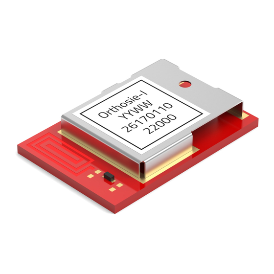
LE profiles, timing configurations, security configurations as well as power consumption optimizations. Even with it’s small dimensions of 9.5 mm x 13 mm, Orthosie-I provides a strongly miniaturized integrated PCB antenna. The main functionality is accessible through pads underneath the radio module. -
Page 8: Block Diagram
RF Filter & 50 Ω matching Antenna Figure 2: Block diagram 1.3 Ordering information WE order code Description Orthosie-I BYOF module with integrated PCB 2617011022000 antenna, Tape & Reel 2617029022001 Evaluation board with Orthosie-I module mounted Table 1: Ordering information Order code 2617011022000 Version 1.0, April 2024... -
Page 9: Electrical Specifications
WIRELESS CONNECTIVITY & SENSORS User manual Orthosie-I 2 Electrical specifications If not otherwise stated, measured on the Orthosie-I evaluation board with T = 25 °C, VDD = 3.3 V. 2.1 Recommended operating conditions Description Min. Typ. Max. Unit Temperature range °C... -
Page 10: Radio Characteristics
WIRELESS CONNECTIVITY & SENSORS User manual Orthosie-I 2.4 Radio characteristics Description Test condition Min. Typ. Max. Unit Data rate: 1 Mbps, Max output power 13.4 Power index: 80 Input sensitivity Data rate: 1 Mbps Frequencies 2412 2484 Table 5: WiFi radio characteristics (radiated) Description Typ. -
Page 11: Pinout
WIRELESS CONNECTIVITY & SENSORS User manual Orthosie-I 3 Pinout GPIO21 / U0TXD GPIO0 / XTAL_P GPIO10 GPIO1 / XTAL_N GPIO18 / USB D- GPIO9 / BOOT_EN CHIP_EN GPIO3 GPIO7 Figure 3: Pinout (top view) Order code 2617011022000 Version 1.0, April 2024... - Page 12 WIRELESS CONNECTIVITY & SENSORS User manual Orthosie-I µC Pin Description GPIO0 / General purpose input / output. XTAL_P GPIO1 / General purpose input / output. XTAL_N CHIP_EN Input Reset pin. A low signal resets the module. GPIO3 General purpose input / output.
-
Page 13: Radio Power Settings
WIRELESS CONNECTIVITY & SENSORS User manual Orthosie-I 4 Radio power settings ® The radio module Stephano-I (variant of Orthosie-I with firmware for Bluetooth LE and WiFi ® support) has been certified using Bluetooth LE and WiFi radio. It has passed the certification tests for several countries with the maximum output powers as stated below: ®... -
Page 14: Design In Guide
WIRELESS CONNECTIVITY & SENSORS User manual Orthosie-I 5 Design in guide 5.1 Advice for schematic and layout For users with less RF experience it is advisable to closely copy the relating EV-Board with respect to schematic and layout, as it is a proven design. The layout should be conducted with particular care, because even small deficiencies could affect the radio performance and... - Page 15 WIRELESS CONNECTIVITY & SENSORS User manual Orthosie-I Elements for ESD protection should be placed on all pins that are accessible from the outside and should be placed close to the accessible area. For example, the RF-pin is accessible when using an external antenna and should be protected.
-
Page 16: Placement Of The Module With Integrated Antenna
WIRELESS CONNECTIVITY & SENSORS User manual Orthosie-I Filter and blocking capacitors should be placed directly in the tracks without stubs, to achieve the best effect. Antenna matching elements should be placed close to the antenna / connector, blocking capacitors close to the module. -
Page 17: Reference Design
WIRELESS CONNECTIVITY & SENSORS User manual Orthosie-I 6 Reference design Orthosie-I was tested and certified on the corresponding Orthosie-I evaluation board (order code 2617029022000). For the compliance with the EU directive 2014/53/EU Annex I, the evaluation board serves as reference design. -
Page 18: Ev-Board
WIRELESS CONNECTIVITY & SENSORS User manual Orthosie-I 6.1 EV-Board Figure 6: Reference design: schematic page 1 Order code 2617011022000 Version 1.0, April 2024 www.we-online.com/wcs... - Page 19 WIRELESS CONNECTIVITY & SENSORS User manual Orthosie-I Figure 7: Reference design: schematic page 2 Order code 2617011022000 Version 1.0, April 2024 www.we-online.com/wcs...
-
Page 20: Layout
WIRELESS CONNECTIVITY & SENSORS User manual Orthosie-I 6.2 Layout Figure 8: Top layer (top), bottom layer (bottom) Order code 2617011022000 Version 1.0, April 2024 www.we-online.com/wcs... -
Page 21: Reference Design Assembly Plan
WIRELESS CONNECTIVITY & SENSORS User manual Orthosie-I MOD1 no metal antenna NO METAL 12.5mm PCB edge PCB edge Figure 9: Reference design assembly plan Order code 2617011022000 Version 1.0, April 2024 www.we-online.com/wcs... -
Page 22: Flashing Or Erasing Of The Chipset
6.3 Flashing or erasing of the chipset The debug UART (UART0) of the Orthosie-I is used to bring any kind of firmware on the module. Thus, the debug UART (UART0) must be accessible and an electronic circuit must be added, which controls the /RESET and BOOT_EN pin of the radio module (see figure 10 ). -
Page 23: Flash Download Tool: Erase Or Flash Chipset
WIRELESS CONNECTIVITY & SENSORS User manual Orthosie-I Figure 12: Flash download tool: Erase or flash chipset Order code 2617011022000 Version 1.0, April 2024 www.we-online.com/wcs... -
Page 24: Manufacturing Information
WIRELESS CONNECTIVITY & SENSORS User manual Orthosie-I 7 Manufacturing information 7.1 Moisture sensitivity level This wireless connectivity product is categorized as JEDEC Moisture Sensitivity Level 3 (MSL3), which requires special handling. More information regarding the MSL requirements can be found in the IPC/JEDEC J-STD-020 standard on www.jedec.org. -
Page 25: Cleaning
WIRELESS CONNECTIVITY & SENSORS User manual Orthosie-I by the customer at their own risk. Rework is not recommended. –5°C Max. Ramp Up Rate Max. Ramp Down Rate Preheat Area s max s min Time 25°C to Peak Time Figure 13: Reflow soldering profile After reflow soldering, visually inspect the board to confirm proper alignment... -
Page 26: Potting And Coating
If the product is potted in the customer application, the potting material might shrink or expand during and after hardening. Shrinking could lead to an incomplete seal, allowing contaminants into the component. Expansion could damage components. We recom- mend a manual inspection after potting to avoid these effects. -
Page 27: Safety Recommendations
WIRELESS CONNECTIVITY & SENSORS User manual Orthosie-I 7.4 Safety recommendations It is your duty to ensure that the product is allowed to be used in the destination country and within the required environment. Usage of the product can be dangerous and must be tested and verified by the end user. -
Page 28: Physical Specifications
WIRELESS CONNECTIVITY & SENSORS User manual Orthosie-I 8 Physical specifications 8.1 Dimensions Dimensions 9.5 x 13 x 2 mm Table 11: Dimensions 8.2 Weight Weight <1 g Table 12: Weight Order code 2617011022000 Version 1.0, April 2024 www.we-online.com/wcs... -
Page 29: Module Drawing
WIRELESS CONNECTIVITY & SENSORS User manual Orthosie-I 8.3 Module drawing 13,0 ±0,3 Figure 14: Module dimensions [mm] Order code 2617011022000 Version 1.0, April 2024 www.we-online.com/wcs... -
Page 30: Footprint
WIRELESS CONNECTIVITY & SENSORS User manual Orthosie-I 8.4 Footprint 12,5 0,95 no metal area 0,95 Figure 15: Footprint [mm] 8.5 Antenna free area To avoid influence and mismatching of the antenna, the recommended free area around the antenna should be maintained. As rule of thumb, a minimum distance of metal parts to the antenna of /10 should be kept (see figure 15 ). -
Page 31: Marking
WIRELESS CONNECTIVITY & SENSORS User manual Orthosie-I 9 Marking 9.1 Lot number The 15 digit lot number is printed in numerical digits as well as in form of a machine readable bar code. It is divided into 5 blocks as shown in the following picture and can be translated according to the following table. -
Page 32: General Labeling Information
Labels of Würth Elektronik eiSos radio modules include several fields. Besides the manufac- turer identification, the product’s WE order code, serial number and certification information are placed on the label. In case of small labels, additional certification marks are placed on the label of the reel. - Page 33 WIRELESS CONNECTIVITY & SENSORS User manual Orthosie-I 10 Information for explosion protection In case the end product should be used in explosion protection areas, the following information can be used: The module itself is unfused. The maximum power of the module is 15 dBm for internal antenna.
- Page 34 WIRELESS CONNECTIVITY & SENSORS User manual Orthosie-I 11 Bluetooth SIG listing/qualification Type Data Design name Stephano-I Declaration ID D066310 QDID 227283 (Controller Subsystem) ® Specification name Bluetooth LE 5.0 Project type End product ® Each product containing intellectual property of the Bluetooth Special Interest Group (SIG) must be qualified by the SIG to obtain the corresponding declaration ID.
- Page 35 User manual Orthosie-I 12 References https://www.espressif.com/en/products/software/ [1] Espressif. Espressif SDKs. esp-sdk/overview . [2] Espressif. Espressif tools download page. https://www.espressif.com/en/support/ download/other-tools . [3] Würth Elektronik. Application note 27 - Bluetooth listing guide. http://www.we-online. com/ANR027 . Order code 2617011022000 Version 1.0, April 2024 www.we-online.com/wcs...
- Page 36 Product life cycle Due to technical progress and economical evaluation we also reserve the right to discontinue production and delivery of products. As a standard reporting procedure of the Product Termination Notification (PTN) according to the JEDEC-Standard we will inform at an early stage about inevitable product discontinuance.
- Page 37 WIRELESS CONNECTIVITY & SENSORS User manual Orthosie-I provided information related to their accuracy, correctness, completeness, usage of the products and/or usability for customer applications. Information published by Würth Elektronik eiSos GmbH & Co. KG regarding third-party products or services does not constitute a license to use such products or services or a warranty or endorsement thereof.
- Page 38 Elektronik eiSos homepage for any updates. Your continued usage of the products will be deemed as the acceptance of the change. We recommend you to be updated about the status of new firmware and software, which is available on our website or in our data sheet and manual, and to implement new software in your device where appropriate.
- Page 39 Orthosie-I ........
- Page 40 Contact Würth Elektronik eiSos GmbH & Co. KG Division Wireless Connectivity & Sensors Max-Eyth-Straße 1 74638 Waldenburg Germany Tel.: +49 651 99355-0 Fax.: +49 651 99355-69 www.we-online.com/wireless-connectivity...
Need help?
Do you have a question about the ORTHOSIE-I and is the answer not in the manual?
Questions and answers