Advertisement
Quick Links
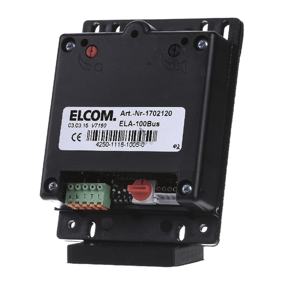
ELA-100
Audio-Modul EB
Door loudspeaker built-in
1
(8)
(7)
(9)
ON
a b T T L
1 2 3 4
(1)
(2)
(3)
2
1
Sicherheitshinweise
Einbau und Montage elektrischer Geräte dürfen
nur durch Elektrofachkräfte erfolgen.
Bei Nichtbeachten der Anleitung können Schä-
e
den am Gerät, Brand oder andere Gefahren ent-
z
stehen.
Bei Installation und Leitungsverlegung die für
SELV-Stromkreise geltenden Vorschriften und
Normen einhalten.
Diese Anleitung ist Bestandteil des Produktes
und muss beim Endkunden verbleiben.
Geräteaufbau (Bild 1)
(1) Anschlussklemmen
Klemme a/b: i2-BUS
Klemme T/T: potenzialfreier Türöffner
Schaltkontakt
Klemme L: Lichttaster Anschluss
(Gegenpol Klemme a oder b)
(2) Betriebsart-Dipschalter
Dipschalter 1:
OFF = Audio-Türstation
ON = Video-Türstation
Dipschalter 2:
OFF = Türöffnung nur bei Verbindung
ON = Türöffnung jederzeit (nur in Eintür-
Anlagen)
Dipschalter 3:
OFF = Quittierungstöne ausgeschaltet
ON = Quittierungstöne eingeschaltet
Dipschalter 4:
ohne Funktion
(3) Drehcodierschalter (rot)
Stellung 0-9:
Adressen für Türlautsprecher im Hauptstrang
Stellung A-F:
Adressen für Türlautsprecher im Nebenstrang
(z. B. Laubengang)
(z. B. Laubengang)
ACHTUNG!
ç
(6)
Adressen dürfen im Strang nicht
doppelt vergeben werden.
(4) Anschluss für Taster-Expander (REH311X)
(5)
(5) Lautstärkeregler
(6) Rote LED: Leuchtet bei abgehendem Ruf
(7) Öffnung zum Herausschieben des Mikrofons
(8) Grüne LED: Leuchtet bei Sprechverbindung
(9) Mikrofonregler
Montage und elektrischer Anschluss
Montage und elektrischer Anschluss
GEFAHR!
ç
Elektrischer Schlag bei Berühren
spannungsführender Teile in der Ein-
bauumgebung!
Elektrischer Schlag kann zum Tod
führen!
(4)
Vor Arbeiten an Gerät oder Last alle
zugehörigen Leitungsschutzschalter
freischalten. Spannungsführende
Teile in der Umgebung abdecken!
Mikrofon-Montage
Zur Verbesserung der akustischen Eigenschaf-
P
ten kann das Mikrofon direkt an der Schall-
eintrittsöffnung einer Frontblende befestigt
werden.
Bei der Montage auf freien Schall ein- und -aus-
P
tritt an Mikrofon und Lautsprecher achten.
z Dazu den Moosgummihalter (11) rückseitig auf
die Türstationfront kleben.
Safety instructions
e
Electrical equipment may only be installed and
assembled by qualifi ed electricians.
Failure to comply with these instructions may
result in damage to the device, fi re or other
hazards.
When installing and laying cables, always com-
ply with the applicable regulations and stand-
ards for SELV electrical circuits.
These instructions are an integral component
of the product and must be retained by the end
user.
Design and layout of the device (Figure 1)
(1) Connecting terminals
Terminal a/b: i2-bus
Terminal T/T: potential-free door release
switching contact
Terminal L: light button connection
(opposite pole for terminal a or b)
(2) Operating mode DIP-switch
DIP-switch 1:
OFF = Audio-door station
ON = Video-door station
DIP-switch 2:
OFF = door release only when connected
ON = door release at any time (only in one-
door
systems)
DIP-switch 3:
OFF = Acknowledge tones switched off
ON = Acknowledge tones switched on
DIP-switch 4:
without function
(3) Rotary encoding switch (red)
Position 0-9:
Addresses for door loudspeaker in main line
Position A-F:
Addresses for door loudspeaker in secondary
line (e.g. pergola)
line (e.g. pergola)
ATTENTION!
ç
Addresses must not be assigned
twice in the line.
(4) Connection for push-button expander (RE-
H311X)
(5) Volume control
(6) Red LED: lights up with outgoing call
(7) Opening for sliding of microphone
(8) Green LED: lights up with intercom connection
(9) Microphone controller
Installation and electrical connection
DANGER!
ç
Touching live parts in the installation
environment can result in an electric
shock!
An electric shock can be lethal!
Before working on the device or load,
disconnect all associated circuit
breakers. Cover all live parts in the
area!
Microphone installation
To improve the acoustic properties, the micro-
P
phone can be attached directly to the sound
entry hole of a front plate.
During installation, ensure that the sound entry
P
and exit on microphone and loudspeaker are
free.
z To do so, stick the microcellular rubber holder
(11) on the backside of the door station front.
Hager Controls, BP10140, 67703 Saverne Cedex, France
z
Advertisement

Related Manuals for ELCOM ELA-100

Summary of Contents for ELCOM ELA-100
- Page 1 Klemme a/b: i2-BUS (1) Connecting terminals Terminal a/b: i2-bus Klemme T/T: potenzialfreier Türöffner Schaltkontakt Terminal T/T: potential-free door release ELA-100 switching contact Klemme L: Lichttaster Anschluss (Gegenpol Klemme a oder b) Terminal L: light button connection Audio-Modul EB (opposite pole for terminal a or b)
- Page 2 z Mikrofon (10) mittels eines Schrauben drehers z Slide the microphone (10) forwards using a nach vorne herausschieben und in den Moos- screwdriver and push into the microcellular gummihalter stecken. rubber holder. Anschluss am abziehbaren Klemmblock (Bild 4) Connection on removable terminal block Leiter anschließen (Figure 4) (10)
Need help?
Do you have a question about the ELA-100 and is the answer not in the manual?
Questions and answers