Table of Contents

Related Manuals for Sennheiser MKH 415 T


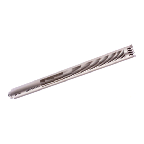
Summary of Contents for Sennheiser MKH 415 T
- Page 1 ~ E R Studio-Richtmikrofon MKH 415 T MKH 415 T-U Studio Directional Microphone MKH415 T MKH415 T-U SEN N HEl S E R E L E CT R 0 N IC 3002 Bissendorf/Hann. Telefon (051 30) 8011 . Telex 0924623...
- Page 2 Gleichspannung wird über die noises is low due to the relative high acous- Der Frequenzgang des Mikrofons ist so aus- beiden Tonadern des Anschlußkabels zuge- tical membrane pressure. The MKH 415 T gelegt, daß...
-
Page 3: Allgemeine Daten
DIN 41524 DIN 41524 Cannon-Stecker (XLR) auf. Beschaltung 1 : NF, 2 : Gehäuse, 1 : Gehäuse, 2 : NF, Wiring 1 : Audio, 2 : Earth, 1 : Earth, 2 : Audio, 3 : NF 3 : NF nach IEC-... -
Page 4: Technische Daten
Fe Id-Lee rlauf-O bert ragungs- Sensitivity at 1000 Hz 20 mV/Pa ~ 2 mV/~bar :!: 1 dB faktor bei 1000 Hz 20 mV/Pa ~ 2 mV/~bar :!: 1 dB Impedance approx. 20 Q symmetrieal, ca. 20 Q, symmetrisch, erdfrei Elektrische Impedanz. -
Page 5: Frequency Response
"d Bet"'"",""c'g E -, (U, Be"'o"","""'g Sollfrequenzgang mit Toleranzschema MKH 415 T Standard response curve with tolerances MKH 415 T . HOch""",",,C"C" ccdBe<,leb",""c'g P -, IU) bei. Jedem Mikrofon legen wir das Original-Meßprotokoll The original diagram is included with each microphone. - Page 6 Niederfrequenzschaltung eine die Tonfrequenzspannung, so daß die Schal- niederohmige Impedanz dar. An der Kapsel tung im Mikrofon nicht galvanisch mit Masse liegt anstelle der sonst nötigen hohen Pola- verbunden ist. Durch diese "erdfreie Tech- risationsspannung lediglich...
- Page 7 High Frequency Circuit only two wires are required to connect the microphone when this powering system is The capsule of a HF condenser microphone being used. The operating current is fed presents, contrary to low frequency circuits, along the same wires as the audio frequency a low impedance output.
- Page 8 Für größere Anlagen steht das Netz- unter schwierigen Verhältnissen nicht not- der Eingangsimpedanz des Verstärkers gerät MZN 6 zur Speisung von bis zu 6 Mi- verlangt wird, daß sie mindestens 200 Q be- wendig, besondere Maßnahmen, wie Dop- krofonen zur Verfügung. Dabei ist zu beach- trägt.
- Page 9 MZN 6, which can feed up to six micro- of the Sennheiser condenser microphones phon es, can be used. It should be noted with A-B powering is so low (approx. 20 Q) take special...
- Page 10 Speisewiderstände betragen teilung muß natürlich berücksichtigt werden. fone mit Hilfe eines Spannungsteilers her- dabei 2 x 180 Q ::!:: 1 %. Das heißt, es fallen Dieselbe Methode wird angewandt, wenn unterzusetzen. Dieser soll in der Mikrofon- etwa 2 V an den Speisewiderständen eine höhere...
- Page 11 200 Q, Connection to Amplifiers with High Input be 12 volts :t 2 volt. It should be so stabi- This is usual in the majority of cases. How- Sensitivity lised and filtered, that the unweighted noise...
- Page 12 +12V ,---: ,--' - ~--,\ ~--: _J r..J "'; 7'-\° 1:..., L--I L _- :1:" ___I 1800 1800 -12V -.th--,_-: ~_-L--h--J TONADERSPEISUNG nach DIN 45595 TONADERSPEISUNG unsymmetrischer Anschluß A-[J powering according 10 DIN 45595 A-B powering unbalanccd conneclion .~)).i "...
- Page 13 Schaltbild MKH 415 T ~{{ircuit Diagram MKH 415 T .TdB "TdB 0 d. :}7B Wlde,,'andsvadatlon Empllndlkhkeltsko"ektur. , 5< , 71012 , (nur paarig auswechseln.) "5 Resls'o, "lues 'o' sensl'lvl'y 1615 13,12.11 2.1< 8" 9,10 co"ec1lon. (Replace only as pal,,) Schaltbild MKH 415...
- Page 14 (Art. No. 0895) Mount MZS 415 Shock (Art. No. 0938) The foam-rubber-windshield should be drawn over the sound The shock mount can be connected to all tripods, booms, etc. inlets of the microphone when wind disturbances are evident. with 'I."...
- Page 15 '/," threads. The MZT 441 is tagether with the swivel mount MZG 415 and the microphone clamp MZa 415 or the shock mount MZS 415 a stable desk stand for the MKH 415 T, Gelenkarm MZG 415 (Art.-Nr.0943) Der Gelenkarm ermöglicht...
- Page 16 Mikrofon getrennt werden, wenn er nicht in Gebrauch ist. Steckverbinder. 3pol. nach DIN 41 524 der Reihe. . . 5 T oder. . . 5 T-U geeignet..5 T . . .5 T-U. mierophones of the se ries...
-
Page 17: Power Supplies
Crosstalk attenuation between channels is greater than 100 dB. Only one microphone can be used with the MZN 5-1 if the inputs Connectors Miniature edge connectorT 2700 (Amphe- are unbalanced or it is necessary to make the inputs ungrounded nol-Tuchel). - Page 18 A switehable roll-oft-filter is ineluded. socket, A switchable roll-oft-filter is ineluded in both channe/s. Frequency reduction a\ 50 Hz approx. 6 dB, at 25 Hz ;;;; 15 dB. Dimensions in mm 85x40x25 Conneetors 170 x 60 x 28 Dimensions in mm 22 <:p x 152...
- Page 19 (Art.-Nr.1033) (Art.-Nr. 0255 und 0256) AnschluBkabel KAM 1-5 (Art.-Nr.0935) Phantom-Adapter MZA 56 P-U (Art.-Nr. 1034) Für den Anschluß an Mikroport-Sender SK 1006, SK 1007, SK 1008 Dreiadrig abgeschirmtes Kabel. 3poligem Normstecker nach DIN 41 524. und den Reportagesender SER 1. Die Mikrofone werden aus den Für...
Need help?
Do you have a question about the MKH 415 T and is the answer not in the manual?
Questions and answers