Table of Contents
Advertisement
Quick Links
Advertisement
Table of Contents

Related Manuals for Badger Meter Cox FC30


Summary of Contents for Badger Meter Cox FC30
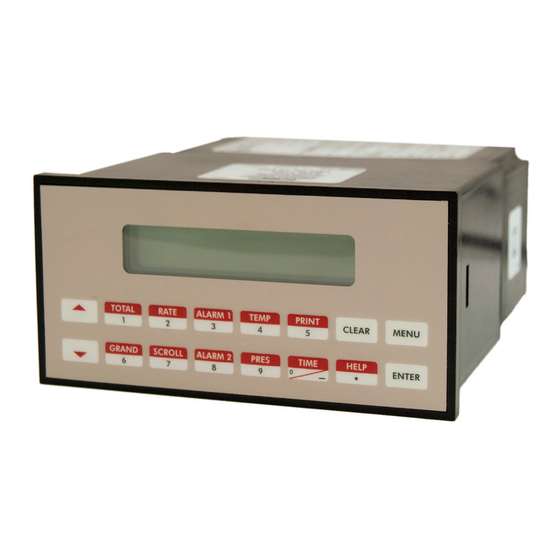
- Page 1 Flow Computers Model FC30 User Manual CXX-UM-02475-EN-02 (October 2021)
-
Page 2: Table Of Contents
Flow Computers, Model FC30 CONTENTS Scope of This Manual Unpacking and Inspection Safety Considerations Terminology and Symbols Handling Procedure Safety Instructions Symbols Used on the Unit Description Features Specifications Modes of Operation Operating Mode Setup Mode Maintenance Mode RS-232 Serial Port Operation of Serial Communication Port with Printers Operation of Serial Port with Modems (Optional) Installation... - Page 3 User Manual Batcher Wiring Rate / Total Wiring with RTD Thermistor Wiring Wiring in Hazardous Areas Unit Operation Front Panel Operation Concept for Run Mode General Operation Pause Computations Prompt Batcher Operation Programming Front Panel Operation Concept for Program Mode Setup Menus Setup Sub-Menus Principle Of Operation...
- Page 4 Flow Computers, Model FC30 Using the Flow Computer Setup Software Setup Tab View Tab Misc Tab Glossary Of Terms Diagnosis and Troubleshooting Response of FC30 on Error or Alarm: Diagnosis Flow Chart and Troubleshooting Error & Warning Messages Fluid Properties Table Liquid Page iv CXX-UM-02475-EN-02...
-
Page 5: Scope Of This Manual
Scope of This Manual SCOPE OF THIS MANUAL This manual describes how to install and program the FC30 Flow Computer The electronic version of this manual is available on our website at www.badgermeter.com MPORTANT Read this manual carefully before attempting any installation or operation. Keep the manual in an accessible location for future reference. -
Page 6: Safety Instructions
Safety Instructions SAFETY INSTRUCTIONS The following instructions must be observed • This instrument was designed and is checked in accordance with regulations in force EN 60950 (“Safety of information technology equipment, including electrical business equipment”) • A hazardous situation may occur if this instrument is not used for its intended purpose or is used incorrectly Please note operating instructions provided in this manual •... -
Page 7: Features
Description Features The FC30 Flow Computer offers the following features: • Supports Single and Dual Rotor Turbine Flow meters • Universal Viscosity Curve (UVC) and Strouhal/Roshko Advanced Linearization Methods • Gas & Liquid Flow Equations (Volume, Mass, Corrected Volume) • API 2540, AGA-7 Equations •... -
Page 8: Specifications
Specifications SPECIFICATIONS CE Compliant, UL/CUL Listed 110V AC 85…127V rms at 50/60 Hz 220V AC 170…276V rms at 50/60 Hz Power Requirements 10…14V DC 300 mA Max 14…28V DC Linearization 40-point linearization table Internal Equations Strouhal-Roshko, API 2540 and AGA-7 Operating Temp 32…122°... - Page 9 Specifications Two auxiliary/compensation inputs are available and are menu selectable for temperature, pressure and density or not used These inputs are used for calculating compensated flow output It can also be used as a general purpose input for display and alarming Accuracy ±...
-
Page 10: Modes Of Operation
Modes of Operation MODES OF OPERATION Operating Mode In Operating mode, the Flow Computer makes a series of measurements of flow, temperature/ pressure/density sensors and then performs calculations to arrive at a result(s), which are then updated periodically on the display The analog output, the pulse output, and the alarm relays are also updated The cycle then repeats itself In Operating mode, you can perform the following actions: Action... -
Page 11: Maintenance Mode
RS-232 Serial Port It is possible to enter in a nominal constant value for temperature or density, or analog flow inputs by placing the desired nominal value into both the lo and hi values This is also a convenience when performing bench top tests without simulators Maintenance Mode The Maintenance mode of the FC30 is the Test and Calibration Mode for the device This mode provides a number of specialized utilities required for factory calibration, instrument checkout on startup, and periodic calibration documentation... -
Page 12: Operation Of Serial Communication Port With Printers
Installation Operation of Serial Communication Port with Printers The RS-232 channel supports a number of operating modes One of these modes is intended to support operation with a printer in metering applications requiring transaction printing, data logging and/or printing of calibration and maintenance reports For transaction printing, the user defines the items to be included in the printed document The user can also select what initiates the transaction print generated as part of the setup of the instrument The transaction document may be initiated via... -
Page 13: Permanently Connected Equipment
Dimensions Permanently Connected Equipment UL 3101-1, Section 6 12 2 1 specifies that: • A switch or circuit breaker shall be included in the building installation; • It shall be in close proximity to the equipment and within easy reach of the OPERATOR; •... -
Page 14: Applications
Applications APPLICATIONS Liquid Volume Measurements A flow meter measures the actual volume in a liquid line A temperature sensor can also be installed to correct for liquid thermal expansion (see “Corrected Liquid Volume” on page 15) Calculations Volume flow is calculated using the flow meter frequency output and the user entered K-Factor Pulse input, average k-factor input frequency * time scale factor Volume Flow =... -
Page 15: Corrected Liquid Volume
Applications Corrected Liquid Volume Measurements A flow meter measures the actual volume in a liquid line A temperature sensor is installed to correct for liquid thermal expansion Calculations Corrected Volume is calculated using the flow and temperature inputs as well as the thermal expansion coefficient stored in the flow computer Use the Set Fluid Properties submenu to define reference temperature and density values for standard conditions Pulse input, average k-factor... -
Page 16: Liquid Mass
Applications Liquid Mass Measurements Actual volume is measured by the flow element Temperature is measured by the temperature transmitter A density transmitter can be used for direct density measurements or a pressure transmitter may be utilized Calculations The density and mass flow are measured directly or calculated using the reference density and the thermal expansion coefficient of the liquid (see Set Fluid Properties submenu) Pulse input, average k-factor input frequency * time scale factor... -
Page 17: Batching
Applications Batching Measurements A flow meter measures the actual volume in a liquid line A temperature sensor can also be installed to correct for liquid thermal expansion (see “Corrected Liquid Volume” on page 15) Calculations Volume flow is calculated using the flow meter frequency output and the user entered K-Factor input frequency * time scale factor Volume Flow = K-Factor... -
Page 18: Corrected Gas Volume
Applications Corrected Gas Volume Measurements A flow meter measures the actual volume flow in a gas line Temperature and pressure sensors are installed to measure temperature and pressure Calculations Corrected Volume is calculated using the flow, temperature and pressure inputs as well as the gas characteristics stored in the flow computer (see Fluid Data submenu) Use the Fluid submenu to define reference temperature and reference pressure values for standard conditions Pulse input, average k-factor... -
Page 19: Gas Mass
Applications Gas Mass Measurements A flow meter measures the actual volume flow in a gas line Temperature and pressure sensors are installed to measure temperature and pressure Calculations Density and mass flow are calculated using gas characteristics stored in the flow computer Mass Flow = Actual Volume Flow * ρ... -
Page 20: Wiring
Wiring WIRING Batcher Wiring (+) V DC OUTPUT FLOW Signal PULSE IN 1 Signal PULSE IN 2 Common COMMON --------- Vin + Press/Dens DUAL ROTOR RTD EXCIT + Thermistor COMP TURBINE RTD SENS Iin + Temp FLOW METER Iin + Press/Dens RTD SENS - Stop Start... -
Page 21: Wiring In Hazardous Areas
Wiring Wiring in Hazardous Areas Examples using MLT787S+ Barrier (MTL4755ac for RTD) Temperature Input (4…20 mA Transmitter) Hazardous Area Safe Area 24V Out Common – 4-20 mA Temp. 4-20 4-20 mA In Transmitter Diode Figure 13: 4…20 mA transmitter Temperature Input (RTD) Hazardous Area Safe Area Common... -
Page 22: Unit Operation
Unit Operation UNIT OPERATION Front Panel Operation Concept for Run Mode The FC30 is fully programmable through the front panel Please review the following usage summary before attempting to use the instrument TOTAL RATE ALARM 1 TEMP PRINT CLEAR MENU TIME HELP GRAND... -
Page 23: General Operation
Unit Operation General Operation This instrument is used primarily to monitor flow rate and accumulated total The inputs can be software configured for a variety of flow meter, temperature and pressure sensors The standard output types include: Pulse, Relay, Analog and RS-232 The unit can display the flow rate, total and process variables RS-485 is an available option for a second communication channel Ratemeter/Totalizer Operation... -
Page 24: Pause Computations Prompt
Unit Operation PC Communications The Setup Disk also allows the user to query the unit for operating status such as Flow Rate, Flow Total, Temperature, Pressure, Density, Presets and so on Operation of RS-232 Serial Port with Printers Transaction Printing The user defines the items to be included in the printed document (see section 6 3 20 SET DATA OUTPUT, Select_list) The transaction document can be initiated by pressing PRINT or by a remote contact closure... - Page 25 Unit Operation Auto Batch Restart The Auto Batch Restart function allows the user to set an amount of time to automatically restart a batch after the completion of a batch This time can be set from 1 to 99 seconds Time Delay The Time Delay for Auto Batch Restart functions as follows: When a batch is completed, the next batch will automatically start after the amount of time entered here...
- Page 26 Unit Operation Relay Operation in Batcher mode Up to four relays are available (two standard) for alarm outputs Preset 1 (RLY1) is reserved for batch amount, Preset 2 (RLY2) is reserved for prewarn Preset 1 (RLY1) and Preset 2 (RLY2) are easily accessible by pressing the PRE 1 or PRE 2 key on the front panel Preset 3 and Preset 4 are accessible only through the setup menu Relays 3 and 4 can be assigned to trip according to rate, total, temperature, pressure, density, overrun or alarm When rate, temperature, pressure or density is selected the relays can be programmed for low or high alarms...
-
Page 27: Programming
Programming PROGRAMMING Front Panel Operation Concept for Program Mode The FC30 is fully programmable through the front panel Please review the following usage summary before attempting to use the instrument Mode Changes Pressing the MENU key will offer selections of RUN, SETUP, TEST RUN is the normal operating mode for the instrument SETUP offers various sub-menus used for instrument setup TEST offers various sub-menus for Test, Calibration and System Start-up Submenu Group Navigation Use the UP and DOWN arrow keys to navigate up and down through the Sub-Menu groups when in the SETUP or TEST mode... -
Page 28: Setup Menus
Programming Setup Menus Menus Display Notes Select Setup to enter the instrument setup routine SELECT OPERATE STATE Setup Test MENU ENTER Top Level Setup Menu “Instrument Type” on page 29 INSTRUMENT TYPE START STOP START SELECT FLOW EQUATION Submenu Groups “Select Flow Equation” on page 30 STOP START “Setup Indicators”... -
Page 29: Setup Sub-Menus
Programming Setup Sub-Menus Menus Display Notes Instrument Type Press ENTER to enter Instrument Type submenus INSTRUMENT TYPE ENTER INSTRUMENT TYPE Rate/Tot Press ENTER when Rate/Total is flashing to configure the instrument as Rate/Tot Batch a Ratemeter/ Totalizer STOP ENTER START Advance To If you selected Rate/Tot, advance to Select Flow Equation SELECT FLOW EQUATION... - Page 30 Programming Menus Display Notes Select Flow Press ENTER to enter Select Flow Equation submenus SELECT FLOW EQUATION Equation ENTER SELECT FLUID MEDIA Press ENTER when desired fluid media is flashing Liquid ENTER SELECT FLOW EQUATION Press ENTER when desired flow equation is flashing Volume Mass Cor/Vol...
- Page 31 Programming Submenus Display Notes Setup Indicators Press ENTER when Rate is flashing to configure the Ratemeter SETUP INDICATORS Tot Dns Pres Indicators (Rate) ENTER RATE TIME BASE Select a Rate Time Base Hour ENTER RATE DESCRIPTOR Enter a Descriptor for the Ratemeter RATE ENTER RATE DEC PLACES (0-3)
- Page 32 Programming Submenus Display Notes SETUP INDICATORS Setup Indicators Press ENTER when Pr is flashing to configure the Pressure Indicators Pres Tot Dns Rte Tmp (Pressure) ENTER Enter the Pressure Units Referenced PRES UNITS Absolute Gauge ENTER Enter the Pressure Descriptor using the up/down arrow keys PRESSURE DESCRIPTOR PRESS ENTER...
- Page 33 Programming Submenus Display Notes Setup Flow Input Press ENTER to begin setup of Flow Input SETUP FLOW INPUT ENTER Select an Excitation Voltage EXCITATION VOLTAGE ENTER PULSE INPUT TYPE NOTE: Enter a Pulse type See side note ChA = Single Pulse Dual Qx1 A=B = Pulse Security Dual = Dual Rotors...
- Page 34 Programming Submenus Display Notes Setup Flow Input If you selected StRo, enter the St/Ro pair for each point LINEAR TABLE KA in the Linearization Table (channel A) RoA01:######## (continued) ENTER OTE: Enter 0 for Ro value of any point (other than LINEAR TABLE KA RoA01) to exit the routine and use the values StA01:#######...
- Page 35 Programming Submenus Display Notes Setup Aux1 Input Press ENTER to begin setup of the Auxiliary 1 Input SETUP AUX1 INPUT ENTER Select Temperature to set the Auxiliary 1 Input for Temperature inputs AUX1 INPUT TYPE Temp None ENTER Choose Temperature Signal Type (If RTD selected, AUX2 will not be AUX1 SIGNAL TYPE available for Density or Pressure) Therm...
- Page 36 Programming Submenus Display Notes Setup Aux2 Input Press ENTER to begin setup of the Auxiliary Input 2 SETUP AUX2 INPUT ENTER NOTE: Select Pressure to set the Auxiliary Input 2 for Pressure inputs AUX 2 INPUT TYPE When Density (Dens) None Dens Press...
- Page 37 Programming Submenus Display Notes SET FLUID PROPERTIES Set Fluid Press ENTER at this prompt to Set Fluid Properties Properties ENTER Up to 10 Fluid types may be stored in the unit Select the number of the FLUID NUMBER (0-9) fluid you want to edit ENTER FLUID NAME Shows name and number of the fluid selected Enter the desired name...
- Page 38 Programming Submenus Display Notes Setup Pulse Press ENTER at this prompt to setup the Pulse Output SETUP PULSE OUTPUT Output ENTER Select a Pulse Output Usage PULSE OUTPUT USAGE CVol/Mass ENTER Select a Pulse Width for the Pulse Output PULSE WIDTH 10mS 100mS ENTER...
- Page 39 Programming Submenus Display Notes Setup Relays SETUP RELAYS Select the Relay for setup Relays 3 & 4 Optional Rly1 Rly2 Rly3 Rly4 (Relay 1 & Relay 2) ENTER NOTE: If you selected Relay 1 or Relay 2, select Rate, Total or NA RELAY 1 USAGE In Batch mode, RATE...
- Page 40 Programming Submenus Display Notes Setup Relays Select the Relay for setup Relays 1 & 2 optional SETUP RELAYS Rly3 Rly4 Rly1 Rly2 (Relay 3 & Relay 4) ENTER NOTE: If you selected Relay 3, choose Rate, Total, Aux, Ovr RELAY 3 USAGE Settings for Relays 3 &...
- Page 41 Programming Submenus Display Notes Setup SETUP CONTROL INPUTS Press Enter to begin setup of the Control Inputs Control Inputs (Rate/Total) ENTER SETUP CONTROL INPUTS Select a Control Input for setup Input1 Input2 Input3 ENTER CONTROL INPUT1 USAGE If you selected Control Input 1, select Inhibit Total or NA (Not Assigned) INHIBIT_TOTAL CONTROL INPUT2 USAGE If you selected Control Input 2, select Reset Total or NA (Not Assigned)
- Page 42 Programming Submenus Display Notes SETUP REALTIME CLOCK Setup Press Enter to begin setup of the Realtime Clock Realtime Clock (Time) ENTER Select Time to set the time SETUP REALTIME CLOCK Time Date ENTER Select 24Hr or 12Hr clock CLOCK TYPE 24HR 12HR ENTER...
- Page 43 Programming Submenus Display Notes Serial Usage SERIAL USAGE Press Enter to begin setup of the Serial Port (RS-232/485) ENTER Select Serial Hardware type for standard port (See SETUP NETWORK SERIAL HARDWARE CARD for RS485 Modbus option ) RS232 RS485 ENTER Select the Device ID DEVICE ID ENTER...
- Page 44 Programming Submenus Display Notes Serial Usage Select Yes to have the unit perform a Call Out transmission upon error/ CALL ON ERROR/ALARM alarm condition (Modem Options, ENTER continued) Call Out Phone Number to be dialed for "Call Out Time" or "Print On CALL OUT PHONE # Error/Alarm"...
- Page 45 Programming Submenus Display Notes Setup Datalog/ Press ENTER to begin Setup Datalog/Print routine SET DATALOG/PRINT Print (Select_list) ENTER Press ENTER when Select_list is selected to setup print list SET DATALOG/PRINT Con g Select_list PRINT LIST ITEMS Use Up and Down arrow keys to view list status List Items: STOP FLUID...
- Page 46 Programming Submenus Display Notes Setup Press Enter to setup Network Card SETUP NETWORK CARD Network Card (Optional) ENTER Select a Network Protocol SELECT NTW PROTOCOL Modbus ENTER NETWORK DEVICE ID Enter the device address on network (00…255) ENTER BAUD RATE Select a desired Baud Rate 2400 4800 9600 19200 ENTER...
-
Page 47: Principle Of Operation
Principle Of Operation PRINCIPLE OF OPERATION The FC30 Flow Computer uses several internal calculations to compute the compensated flow based on specific data input Several computations are performed to arrive at the uncompensated flow, temperature, pressure, density and viscosity This information is then used to compute the Corrected Volume Flow or Mass Flow OTE: The user will be prompted for Fluid Information during the setup of the instrument See also Appendix A for common... - Page 48 Principle Of Operation API 2540 Density Equation The above information was obtained from "Flow Measurement Engineering Handbook, 3rd Edition" by Richard W Miller API 2540 Expansion Factor Equation 1 Select the values for K and K for the fluid group to be measured 2 Convert the base reference density for your fluid into the corresponding density units of kg/m 3 Solve for α...
-
Page 49: Calculating The Fluid Expansion Factor
Principle Of Operation Calculating the Fluid Expansion Factor The liquid density is a function of the flowing temperature for many fluids This unit solves an equation which represents this physical property of the fluid The information which the unit uses to describe the fluid is entered by the user in the following variables: Reference Temperature, Reference Density, Fluid Expansion Factor Values for common fluids are listed in Appendix A This information is available for many fluids in one or more of the following forms: •... -
Page 50: Computation Of Viscosity Coef A And B
Principle Of Operation Computation of Viscosity Coef. A and B The flow computer solves an equation that computes the viscosity as a function of temperature Two parameters must be entered for this calculation to be performed These are the setup parameters Viscosity Coef A and Viscosity Coef B A table listing these values for common fluids is available in Appendix A Alternately, if your intended fluid is not listed, the Viscosity Coef A and B can be derived from two known temperature/ viscosity pairs Begin by obtaining this information for the intended fluid Convert these known points to units of Degrees F... -
Page 51: Universal Viscosity Curve (Uvc)
Principle Of Operation Linearization Table Interpolation The Linearization Table routine uses the entered data to determine the K factor for any given input frequency or input flow signal This is done by taking the closest data points above and below the input signal, then using those points to extrapolate the K-factor (correction factor), then calculating the uncompensated flow from the data Below are the formulas Parameters Determine closest point above input signal;... -
Page 52: Test, Service And Maintenance
Test, Service and Maintenance TEST, SERVICE AND MAINTENANCE Test Menus Menus Display Notes Select Test to enter the instrument test and SELECT OPERATE STATE calibration routine Test Setup NOTE: Supervisor (Service) password required to gain access to this ENTER mode Audit Trail Top Level Test Menu “Audit Trail Submenu Group”... - Page 53 Test, Service and Maintenance Submenus Display Notes Audit Trail Submenu Audit Trail Group ENTER The configuration Audit Trail format: Con g_Audit nnnnn nnnnn= number of critical menu changes, hh:mm:ss mm/dd/yy hh:mm:ss; mm/dd/yy = time and date of last change MENU The calibration Audit Trail format: Cal_Audit nnnnn...
- Page 54 Test, Service and Maintenance Submenus Display Notes Keypad Test Press ENTER to enter Keypad Test. Keypad Test Submenu Group ENTER Keypad Test Press any key and the display shows the key you pressed Press MENU to exit the test Key pressed—> MENU Keypad Test Press MENU to return to Keypad Test top-level menu...
- Page 55 Test, Service and Maintenance ALL UNITS ARE CALIBRATED AT THE FACTORY PRIOR TO SHIPMENT. THIS UNIT MUST BE CALIBRATED USING PRECISION AND CALIBRATED EQUIPMENT. EQUIPMENT REQUIRED IS AS FOLLOWS: FREQUENCY GENERATOR, DIGITAL MULTIMETER, PRECISION CURRENT/VOLTAGE SOURCE, OSCILLOSCOPE AND FREQUENCY COUNTER. Submenus Display Notes...
- Page 56 Test, Service and Maintenance Calibrate Aux2: 0 mA Submenu Group Submenus Display Notes Calibrate Aux2: 0 mA Calibrate Aux2: Connect Current Source (+) TB1-8, (-) TB1-4 Input 0 mA and press Iin=TB1-8 GND=TB1-4 Submenu Group ENTER ENTER Calibrate Aux2: This message displays during calibration 0 CALIBRATING ------ This message displays during calibration Calibrate Aux2:...
- Page 57 Test, Service and Maintenance Submenus Display Notes Cal Therm: 100 Ohms Cal Therm: 100 Ohms Place a 100 Ω 0 1% resistor between TB1-6 and TB1-4 Press Therm TB1-6 to TB1-4 Submenu Group ENTER to calibrate ENTER This message displays during calibration Cal Therm: 100 Ohms 0 CALIBRATING ------ This message displays when the calibration is finished...
- Page 58 Test, Service and Maintenance Submenus Display Notes Calibrate Aux2: 0V Calibrate Aux2: Connect Voltage Source (+) TB1-5, (-) TB1-4 Input 0V and press Vin=TB1-5 GND=TB1-4 Submenu Group ENTER to calibrate ENTER This message displays during calibration Calibrate Aux2: 0 CALIBRATING ------ This message displays when the calibration is finished Calibrate Aux2: *** DONE ***...
- Page 59 Test, Service and Maintenance Submenus Display Notes Calibrate 0 mA Aout Connect ammeter to (+) TB1-15, (-) TB1-16 Press ENTER Calibrate 0mA Aout Submenu Group + TB1-15 - TB1-16 ENTER To trim 0 mA analog output: Press CLEAR to enable editing and Calibrate 0mA Aout enter a small negative number (for instance -0 100) to force a display...
- Page 60 Test, Service and Maintenance Pulse Input Test Press ENTER to test the Pulse Input Pulse Input Test Pulse Input Test Submenu Group ENTER Use the Up/Down arrow keys to select the trigger level Pulse Input Test START Trigger Level 2.5V STOP ENTER Use the Up/Down arrow keys to select the frequency range...
- Page 61 Test, Service and Maintenance Submenus Display Notes Pulse Out Test Press ENTER to test the pulse output Pulse Out Test Submenu Group ENTER To simulate a frequency on the pulse output: Connect a frequency Pulse Out Test *0Hz 1Hz 10Hz 20Hz counter to (+) TB1-13, (-) TB1-14 Press the key under the required setting to move the asterisk (*) The unit outputs the selected...
- Page 62 Test, Service and Maintenance Submenus Display Notes Battery Voltage Test Press ENTER to view the battery voltage Battery Voltage Test Submenu Group ENTER The display shows the battery voltage Replace battery at 2 5V DC or Battery Voltage Test 3.312 Volts below MENU Press MENU to return to Battery Voltage Test top-level menu...
-
Page 63: Internal Fuse Replacement
Test, Service and Maintenance Internal Fuse Replacement 1 Make sure you follow proper E S D Precautions All persons performing this replacement must follow proper grounding procedures 2 Turn off power to the unit 3 Disconnect the two piece connector rear terminal block, leaving all connections in place 4 Remove the unit from the panel 5 Remove the four machine screws (see Figure... -
Page 64: Rs-232 Serial Port
RS-232 Serial Port RS-232 SERIAL PORT The FC30 has a general purpose RS-232 port which may be used for any one of the following purposes: • Transaction Printing Data Logging • Remote Metering by Modem (optional) Computer Communication Link Configuration by Computer •... -
Page 65: Rs-485 Serial Port (Optional)
RS-485 Serial Port (optional) RS-485 SERIAL PORT (OPTIONAL) The FC30 has a an optional general purpose RS-485 Port which may be used for any one of the following purposes: • Accessing Process Parameters • Rate, Temperatures, Density, Pressure, Viscosity, Setpoints, Month, Day, Year, Hour, Minutes, Seconds, etc •... -
Page 66: Flow Computer Setup Software
Flow Computer Setup Software FLOW COMPUTER SETUP SOFTWARE The FC30 setup program provides for configuring, monitoring and controlling an FC30 unit over the RS-232 link Sample applications are stored in disk files The setup program calls these Templates You can store the setup from the program’s memory to either the FC30 (Downloading the file) or to a disk file (Saving the file) for later usage Similarly you can load the setup in program memory from either a disk file (Opening a file) or from the FC30 unit (Uploading a file) The program can monitor outputs from the unit while it is running The program can reset alarms and totalizers... -
Page 67: Setup Tab
Flow Computer Setup Software The Open option will bring up a list of predefined templates that can be loaded into the program These predefined templates are useful as a starting point when defining custom templates A typical scenario using the setup program would be the following: 1 Open up a predefined template from the supplied list 2 Choose ‘Save As’... -
Page 68: Misc Tab
Flow Computer Setup Software Misc. Tab This tab has three sections: Tools, Actions and Options The tools section contains various system administration activities such as creating/ modifying the initial sign-on screen or calibration, service test etc Create Sign-on and Create Print Header The Actions section is used to send commands to the FC30 unit Reset Totalizers, Reset Alarms, Reset Alarm History The Options section has the following selections: Network Card Setup Additional capabilities may be provided in the future... -
Page 69: Glossary Of Terms
Glossary Of Terms GLOSSARY OF TERMS Term Definition Acknowledge & Acknowledge is used to clear alarm relays and remove any visual alarm messages from the display In the Clear Alarms run mode, press the ENTER key or activate CONTROL INPUT 3 (if set for ACK) to momentarily clear alarms and alarm messages Alarms will reassert themselves if alarm conditions are still present Analog Output The analog signal (4-20mA) that is generated by the FC30 It can correspond to the Rate, Total,... - Page 70 Glossary Of Terms Term Definition Follow, Alarm Alarm relays which are non latching and whose output state is based solely on the comparison of the current process value and the alarm setpoint (trip point) Function Key A key on a push-button panel or keyboard (whose function is described by the key label) used to perform an instrument function or special routine Handshake A means of controlling the information flow between two pieces of equipment to prevent the sending...
- Page 71 Glossary Of Terms Term Definition Private Code An operator password code which authorizes changes to the setup of the instrument but blocks access to the Service/Calibration/Test mode The private code also blocks the clearing of the Grand Total Process Sensor information that has been scaled to engineering units including Flow, Temperature and Density Parameters Pulldown (Input The termination of an input at which the input is pulled down to ground through a resistor Inputs that are...
-
Page 72: Diagnosis And Troubleshooting
Diagnosis and Troubleshooting DIAGNOSIS AND TROUBLESHOOTING Response of FC30 on Error or Alarm: Error and warning indications which occur during operation are indicated in the RUN mode alternately with the measured values The FC30 Flow Computer has three types of error: Type of Error Description Sensor/Process Alarms... -
Page 73: Error & Warning Messages
Diagnosis and Troubleshooting Error & Warning Messages Sensor/Process Alarms Error/Warning Message Cause Remedy TOTALIZER ROLLOVER Displayed when totalizer rolls over • Acknowledge rollover • Remedy not required AUX INPUT TOO LOW! 4…20 mA input current at aux input • Check wiring is smaller than 3 5 mA due to faulty •... - Page 74 Diagnosis and Troubleshooting Self Test Alarms Error/Warning Message Cause Remedy AUX INPUT TOO HIGH! Analog input signal of auxiliary input • Check analog signal range exceeded by more than 3%: • Check the application conditions • Sensor over-ranged • Check wiring •...
-
Page 75: Fluid Properties Table
Fluid Properties Table FLUID PROPERTIES TABLE Liquid Coeff. of Ref. Density Ref. Temp. Liq. Visc. Andrede’s Equation Viscosity By Andrede’s Fluid Expansion (lb/gal) (ºF) Coeff. “A” Equation Coeff. “B” (e-6 format) 7 2947 -317 8 1626 2 0 172 Ammonia 5 6996 -28 2 570 4... - Page 76 Control. Manage. Optimize. Cox Instruments is a registered trademark of Badger Meter, Inc Other trademarks appearing in this document are the property of their respective entities Due to continuous research, product improvements and enhancements, Badger Meter reserves the right to change product or system specifications without notice, except to the extent an outstanding contractual obligation exists ©...
Need help?
Do you have a question about the Cox FC30 and is the answer not in the manual?
Questions and answers