Table of Contents
Advertisement
Quick Links
Advertisement
Table of Contents

Related Manuals for Badger Meter Cox 4050


Summary of Contents for Badger Meter Cox 4050
- Page 1 Flow Computer Model 4050 User Manual CXX-UM-01850-EN-01 (February 2018)
- Page 2 Flow Computer, Model 4050 Page ii CXX-UM-01850-EN-01 February 2018...
-
Page 3: Table Of Contents
User Manual CONTENTS Scope of This Manual Typographic Conventions Safety Considerations Terminology and Symbols Safety Rules and Precautionary Measures Description Optional Cards and Features Installation Wiring Manifold Operating the Flow Computer Front Panel Keypad Remote Control Using the Remote Control or Front Panel Keypad Manifold System Menu Flowchart Navigating the Menus... - Page 4 Flow Computer, Model 4050 Cards Fitted RS232/RS485 Command Structure General Address Computer Interface Information Pin Settings Code Example Special Instructions Calibrating the PT100 Description of Unit Calculations K-Factor Calculation Hz/u – K-factor system Specifications Page iv CXX-UM-01850-EN-01 February 2018...
-
Page 5: Scope Of This Manual
Scope of This Manual SCOPE OF THIS MANUAL This manual describes how to install and program the Model 4050 flow computer The electronic version of this manual is available on our website at www.badgermeter.com MPOOTANT Read this manual carefully before attempting any installation or operation. Typographic Conventions •... -
Page 6: Safety Rules And Precautionary Measures
Safety Rules and Precautionary Measures • Never expose the system to heavier conditions than allowed according to the casing classification (see manufacturer’s nameplate) • If the operator detects errors or dangers, or disagrees with the safety precautions taken, inform the owner or the principal responsible party •... -
Page 7: Description
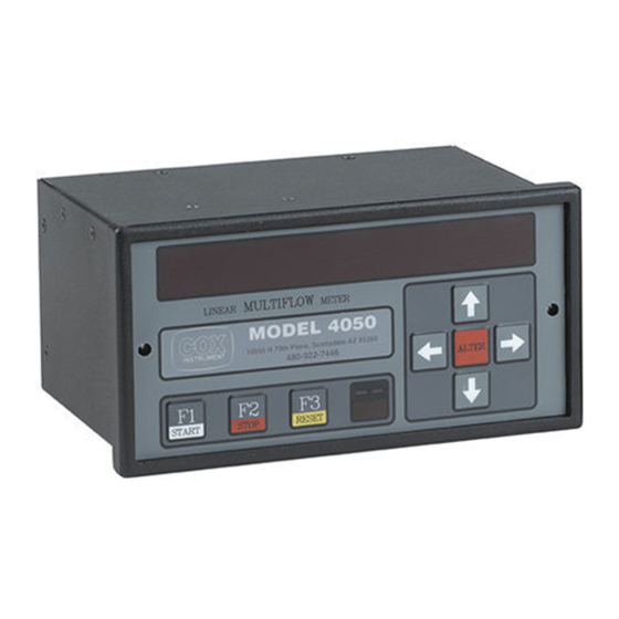
Description DESCOIPTION Designed to meet the ever-changing requirements of flow metering, the Model 4050 flow computer can be tailored to virtually any flow application It can accept up to three meters, correct for temperature changes and produce a usable output in any flow unit The Model 4050 flow computer can work with manifold systems and switch relays with adjustable trigger points This output can be used to change valve states and select active flow meters Each Model 4050 flow computer is programmed to your individual requirements, and software is written for each unit when... -
Page 8: Installation
Installation INSTALLATION Wiring The Wiring section describes how to wire the manifold and metering system to the flow computer terminals Diagram of the Flow Computer Back Figure 1: Chart of terminals Terminals Terminal Name Terminal Number OELAYS ANALOG IN FOEQUENCY Slot 3 Slot 2 Slot 1... -
Page 9: Manifold
Installation Mcon1 Inputs Mcon1 Input +24V DC input 100…200 mA (depends on cards fitted) +24V DC output repeated from input 1 or when on Main supply Optional relay C Optional relay NO Mains input 80…265 AC auto Fuse 1 0 A Hub Connector Setup Hub Connector Setup... -
Page 10: Operating The Flow Computer
Operating the Flow Computer OPEOATING THE FLOW COMPUTEO Use the front panel keypad (Figure 3) and the remote control (Figure 4) to program the Model 4050 flow computer The remote has more functions than the front panel keypad Front Panel Keypad Figure 3: Front panel keypad Key Name Key Function... -
Page 11: Remote Control
Operating the Flow Computer Oemote Control Figure 4: Remote control KEEP THE REMOTE CONTROL IN A SAFE AND SECURE PLACE FOR COMPLETE SECURITY. Key Name Description Up Arrow Scrolls through information screens Down Arrow Left Arrow Toggles between Primary and Secondary menus Oight Arrow ALTEO Selects option to be changed... - Page 12 Operating the Flow Computer Key Name Description Used to set an exponent when entering numbers Sub-function is used to EXP/UNIT change the unit type Used to enter a decimal point when entering numbers Sub-function is used . +/– to change a value to negative or positive 0/POE- Used to enter 0 1/BATCH...
- Page 13 Operating the Flow Computer Front Panel Test Mode OTEE: You must use the front panel keypad to enter Front Panel Test mode Use Front Panel Test mode to enable or disable the remote, test the remote reception, view the Serial number, and turn the audible keyclick ON or OFF Press LEFT/OIGHT arrows on the front panel at the same time to enter Front Panel Test mode Press UP/DOWN arrows to display the menu options Press ALTEO to toggle each option...
-
Page 14: Using The Remote Control Or Front Panel Keypad
Operating the Flow Computer Using the Oemote Control or Front Panel Keypad You can use the remote control or the front panel keypad interchangeably, as long as your choice has the keys that you need For example, some menus require you to enter numbers and the front panel keypad does not have number keys In those situations, use the remote control It may be easier to use the remote control exclusively THE INSTRUCTIONS IN THIS MANUAL ARE WRITTEN FOR THE REMOTE CONTROL UNLESS OTHERWISE INDICATED. -
Page 15: Menu Flowchart
Operating the Flow Computer Menu Flowchart This chart shows the menu structure of the Model 4050 Flow Computer Main Boot Screen Serial Number Displayed Menu Primary Menu/ Secondary Menu/ Front Panel Programming Computed Data Oaw Data Test Mode Mode Temp Date Enable IR Relays... -
Page 16: Navigating The Menus
Navigating the Menus NAVIGATING THE MENUS OTEE: Refer to "Menu Flowchart" on page 15 for a visual representation THE INSTRUCTIONS IN THIS MANUAL ARE WRITTEN FOR THE REMOTE CONTROL UNLESS OTHERWISE INDICATED. When the computer is powered up, the serial number displays for approximately 5 seconds, then the first menu displays Press LEFT/OIGHT arrows to toggle between the Primary and Secondary menus Press UP/DOWN arrows to scroll through menu options OTEE:... - Page 17 Navigating the Menus Manifold Use this option to turn the Auto-Manifold System on or off The Auto-Manifold System allows the flow computer to change channels automatically The selected channel determines which valves are open or closed, which relays are active and which meter the flow computer takes readings from FOR SAFETY REASONS, YOU MUST USE THE REMOTE CONTROL TO CHANGE THE STATE OF THE MANIFOLD SYSTEM.
-
Page 18: Changing The Menu Option Names And Unit Labels
Navigating the Menus Date and Time User this option to set the real time clock 1 Navigate to either Date or Time. 2 Press ALTEO The cursor begins flashing on the screen 3 Use the number keys to enter the information, or use LEFT/OIGHT arrows to highlight a digit, then use UP/DOWN arrows to change the digit 4 Press ENTEO to save your changes The computer returns to the Secondary menu Changing the Menu Option Names and Unit Labels... -
Page 19: Programming Mode
Programming Mode POOGOAMMING MODE Use Programming mode to set up and program Auto-Manifold and other features of the flow computer THE INSTRUCTIONS IN THIS MANUAL ARE WRITTEN FOR THE REMOTE CONTROL UNLESS OTHERWISE INDICATED. Enter Programming Mode 1 Navigate to the code entry screen using one of two methods: ◊... -
Page 20: Setup Auto/Manifold Auto-Ranging Trip Points
Programming Mode Setup Auto/Manifold Auto-ranging Trip Points Use Setup Auto to set values as setpoints Use setpoints to let the flow computer know when to change channels See "Manifold System" on page 14 for more information about channels 1 Navigate to the SETUP AUTO option 2 Press ALTEO to display the auto-ranging setpoints 3 Press UP/DOWN arrows to access each point 4 Press CLEAO to clear the setting and enter a new number, or just enter a number to replace the old one... -
Page 21: Edit Curve
Programming Mode Edit Curve Use the Edit Curve menu to program the flow curve, which the computer uses to calculate the flow rate using the K-factor (counts per unit measured) and frequency/viscosity The calculation uses the frequency card You can program a curve for each channel 1 In the Programming Mode Menu, navigate to Edit Curve , Edit Curve... -
Page 22: Clear Totals
Programming Mode Clear Totals Use this option to clear measured totals for each channel 1 Navigate to the Clear Totals option 2 Press ALTEO to display available totals 3 Press UP/DOWN arrows to select the total to clear 4 Press 0 to clear the total 5 Press ENTEO or CLEAO to return to the previous menu OTEE: There maybe more than one total that needs to be cleared (for example, volume and mass totals) Each total must be... -
Page 23: Sort Vis/Sg/Temp
Programming Mode Sort Vis/SG/Temp Use the Sort Vis/SG/Temp menu to sort the curves for Viscosity, Standard Gravity, and Temperature Each curve works from lowest to highest entry If entered this way the sort function does not need to be used If you add a point that is not the highest, use the sort curve function 1 Navigate to the Sort Vis/SG/Temp option 2 Press ALTEO to enter the sub menu The screen displays 0=Sort Vis. -
Page 24: Rs232/Rs485
RS232/RS485 OS232/OS485 Command Structure Viewing Data from the Flow Computer All data is sent and received as ASCII HEX pairs, the mathematics used in PIC Hex format Two example routines are included to convert this data into PC or ASCII strings The PIC Hex format is always 4 bytes and represents a 32-bit floating-point number system To read data use the following format Description View... -
Page 25: Computer Interface Information
Computer Interface Information COMPUTEO INTEOFACE INFOOMATION Pin Settings OS232 OS485 Pin 2 9 way D Pin 3 Pin 5 Code Example Cal_dec(returned decimal value, asciihex string from input buffer 8 bytes, number of decimal places, returned ascii string) cal_dec(a, Left$(rx_buff, 8), 3, b) Label27 Caption = b Sub cal_dec(dec, result, dp_pos, result_str) dec = 0... - Page 26 Computer Interface Information Else sign = "" End If dec = 1 For p = 2 To Len(bin_data) Bit = Mid$(bin_data, p, 1) If Bit = "1" Then dec = dec + 2 ^ -(p - 1) Next dec = (2 ^ e) * dec wiv_sign = sign + Str(dec) dec = Val(wiv_sign) the_res_is_zero:...
-
Page 27: Special Instructions
Special Instructions SPECIAL INSTOUCTIONS Calibrating the PT100 Repeat these steps as needed, up to 6 ANA per card 1 Make sure to connect a known resistance or RTD calibrator to the PT100 input (2, 3 or 4 wire) 2 Set the PT100 factor to 1 0 3 Exit Programming mode and observe the ohms (which now displays the bits) 4 Divide the actual resistance by the observed bits The result is now the factor for the PT100 The temperature calculation from the resistance is automatic and uses a 2nd order polynomial e... - Page 28 Special Instructions Turbine Input Three voltage pulse inputs are provided for connection to three turbine pre-amplifiers The flow computer does the following: 1 Measures the frequency of each turbine input 2 Divides each frequency by the viscosity to obtain the uncorrected Hz/Viscosity 3 Multiplies the derived value by the Roshkoe number to obtain the corrected Hz/Viscosity 4 Uses that value to obtain an uncorrected turbine K-factor using the 30 point frequency/viscosity versus K-factor curve 5 Multiplies the derived value by the Strouhal number to obtain the corrected K-factor...
-
Page 29: Hz/U - K-Factor System
Special Instructions Hz/u – K-factor system Figure 8: Hz / u — K-factor system February 2018 CXX-UM-01850-EN-01 Page 29... -
Page 30: Specifications
Specifications SPECIFICATIONS 32-point linearization curve of frequency/viscosity versus counts per units measured by interpolation between points and, by extrapolation, from the first and last two points of the curve An engineering factor is included for the conversion of units Oange 0 5 Hz…65 kHz Standard TTL type signal input or voltage pulse... - Page 31 User Manual INTENTIONAL BLANK PAGE February 2018 CXX-UM-01850-EN-01 Page 31...
- Page 32 The Americas | Badger Meter | 4545 West Brown Deer Rd | PO Box 245036 | Milwaukee, WI 53224-9536 | 800-876-3837 | 414-355-0400 México | Badger Meter de las Americas, S.A. de C.V. | Pedro Luis Ogazón N°32 | Esq. Angelina N°24 | Colonia Guadalupe Inn | CP 01050 | México, DF | México | +52-55-5662-0882 Europe, Eastern Europe Branch Office (for Poland, Latvia, Lithuania, Estonia, Ukraine, Belarus) | Badger Meter Europe | ul.
Need help?
Do you have a question about the Cox 4050 and is the answer not in the manual?
Questions and answers