Advertisement
Advertisement
Table of Contents

Related Manuals for Thornwave Labs PowerMon-W


Summary of Contents for Thornwave Labs PowerMon-W
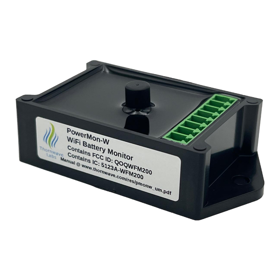
- Page 1 PowerMon-W WiFi / IoT Advanced Battery Monitor / DC Power Meter – USER MANUAL –...
- Page 2 BRIEF PowerMon-W is a WiFi / IoT advanced battery monitor / DC power meter. This tool can be used in any battery or DC powered circuit to monitor, analyze, and log the most important electrical parameters: two voltages (0-72V), current over 1,000A using any external shunt, power (W), energy (Wh), coulombs (Ah) and temperature.
-
Page 3: Direct Connection
PowerMon device. Three types of connections are supported: • Direct connection – from the client to the PowerMon-W which is acting as an access point. This requires the access point feature of the PowerMon device to be on. This is typically used for the initial configuration of the device. -
Page 4: Local Connection
Local Connection Client Cloud Connection... -
Page 5: Typical Applications
FEATURES • Measures two voltages, current, power (W), • Timers • Can use an external temperature sensor charge (Ah), energy (Wh), and temperature • Operates at up to 72V (DS18B20 based) • Can sense up to 160mV of voltage drop •... - Page 6 TERMINAL DESCRIPTION / INTERNAL DIAGRAM Name Terminal Description GROUND System ground (battery negative, chassis) Multi-Function. Supports pushbutton input or external temperature sensor Relay output. It drives a mechanical or solid-state relay. To turn the relay RELAY on, the device is grounding this terminal internally. External shunt connection External shunt connection 5V from the internal regulator.
-
Page 7: Specifications
SPECIFICATIONS Absolute Maximum Ratings Maximum voltage at the V1 and V2 terminals +72V Maximum voltage at the RELAY terminal +72V Maximum voltage at the +5V terminal Maximum current through the RELAY terminal (maximum relay coil current) depends on the external shunt Maximum sensed current (can be over 1,000A) Maximum differential current sense voltage ES1 to ES2... - Page 8 Performance Parameter Value Measured voltage (V1, V2) 0 to 72V Measured voltage accuracy max 0.2%, typ. 0.15% Measured differential voltage on shunt inputs (ES1, -160mV to +160mV ES2) Current monitoring accuracy depends on external shunt precision, typically 0.25% (with calibration) Temperature resolution 1°C / 1°F Data logging sample rate...
- Page 9 Performance Parameter Value Current consumed by the device (using the latest 10-minute averages firmware version, access point on, PowerMonX client app connected) at 12V 19.0mA at 24V 9.5mA at 36V 6.3mA at 48V 4.8mA at 60V 3.9mA at 72V 3.3mA...
-
Page 10: Compliance Statements
COMPLIANCE STATEMENTS ATTENTION: Changes or modifications not expressly approved by Thornwave Labs Inc could void the user's authority to operate the equipment. ATTENTION: This device complies with Part 15 of the FCC rules. Operation is subject to the following two conditions: (1) this device may not cause harmful interference and (2) this device must accept any interference received, including interference that may cause undesired operation. -
Page 11: Safety Instructions
SAFETY INSTRUCTIONS Warning! Read all the instructions and cautions before using the PowerMon-W device. Thornwave Labs Inc does not assume responsibility for any injury or property damage caused by improper installation, bad wiring, or use of PowerMon outside of its intended purpose. The device should be installed by a professional. - Page 12 Warning! PowerMon-W cannot be used as a charge current limiter or LiFePO cell balancer. A properly sized battery charger is required to recharge LiFePO batteries. Thornwave Labs Inc. does not assume any responsibility for expensive battery damage.
- Page 13 Zero the current offset. Due to the high sensitivity of the current measurement circuitry inside the PowerMon-W device, the value displayed may have a small offset (measurement is different than zero even when the actual current is zero). Typically, this is less than 0.1A. In situations where the measurement precision is critical, the offset can be reduced to zero.
- Page 14 This feature also allows the PowerMon-W to operate as a battery isolator. The relay is used to connect the house battery in parallel with the starting battery (see wiring diagrams at the end of this document). The LVD filter value should be set to 5000ms.
- Page 15 Battery fuel gauge. PowerMon computes the battery state of charge and various statistics. This is accomplished by using coulomb counting. For the battery fuel gauge to work properly, charging current should display positive, and discharging current should display negative. If the displayed current sign is wrong, it can be swapped by changing the “Flip Current Sign”...
- Page 16 Connect Conditions (10 sec. delay used) Disconnect Conditions (2 sec. delay used) battery voltage (V1) less than 3.32V / cell battery voltage (V1) greater than 3.65V / cell charger voltage (V2) at least 0.2V above the battery voltage (V1) charging current (I) less than C/100 or 1 Amp, whichever is greater full charge is detected: battery voltage (V1) greater than 3.5V /cell...
- Page 17 Timer4: START 12:00AM. STOP: disabled, REPETITION DOM: 1 Timer5: START disabled, STOP: 12:00AM, REPETITION DOM: 8 This set of timers used together will turn the relay on every 1 of the month at 12:00AM and turn it off 7 days later, on the 8 of the month at 12:00AM.
- Page 18 Power Status: Displays the current power status of the device (RELAY output status). Possible values are: OFF, ON, LVD (Low Voltage Disconnect – device is OFF due to an LVD condition), HVD (High Voltage Disconnect), OCD (Over-Current Disconnect), LTD (Low Temperature Disconnect), HTD (High Temperature Disconnect) and NCH (Not CHarging –...
- Page 19 Disable Voltage 2: Disable the V2 voltage input. Use this option if you don’t use the V2 voltage input and desire to not have it displayed at all. Power Meter Voltage Source: The voltage used to calculate power and energy. Voltage1 or Voltage2 can be selected.
- Page 20 High Voltage Disconnect HVD Voltage Source: The voltage used by the high voltage disconnect feature. Voltage1 or Voltage2 can be selected. HVD Disconnect Threshold (V): The voltage in volts above which the power relay will disengage. HVD Connect Threshold (V): The voltage in volts below which the power relay can re-engage (after the connect filter time has passed).
- Page 21 Auto-off Timer: If enabled the power will turn off automatically after a specified time since it was turned on has passed. This effectively becomes a turn-off timer. Auto-on Timer: If enabled the power will turn on automatically after a specified time since it was turned off has passed.
- Page 22 Turn On Based on SoC: If enabled the generator will be turned on when the battery SoC (State-of-Charge) drops under a specified threshold. Turn On SoC Threshold (%): The threshold in percentage below which the generator will be turned on. Turn Off Based on Voltage: If enabled the generator will be turned off when the battery voltage increases above a specified threshold.
- Page 23 Default Factory Settings. The device can always be reset to the default configuration using the PowerMonX app. To do this, connect to a device, tap the top right corner menu, and then “Device Information”. Tap on Factory Reset. WARNING: When resetting to the factory defaults, all custom settings, and timers will be erased, including the device calibration, the battery fuel gauge internal state, and the data log.
-
Page 24: Wiring Diagrams
WIRING DIAGRAMS Typical application without a relay • The disconnect functions are not available (there is no relay). • V2 can be used to monitor a second battery, the midpoint between two batteries in series, or the solar panel input voltage (max. 72V). Leave unconnected if not used. •... - Page 25 Typical application using a relay • V2 can be used to monitor a second battery, the midpoint between two batteries in series, or the solar panel input voltage (max. 72V). Leave unconnected if not used. • The charging sources are connected before the relay. This is done so they cannot be disconnected from the battery during a low voltage or other disconnect events (very important for an MPPT charge controller).
- Page 26 Typical application of a battery isolator • The disconnect functions are not available • V1 is monitoring the starting battery voltage • V2 is monitoring the house battery voltage • The house battery SoC is monitored. Set the fuel gauge voltage source to V2 (see device configuration)
- Page 27 DIMENSIONS Dimensions are in inches.
- Page 28 ORDERING Part Number Description PowerMon-W WiFi /IoT Advanced Battery Monitor / DC Power Meter...
Need help?
Do you have a question about the PowerMon-W and is the answer not in the manual?
Questions and answers