Table of Contents
Advertisement
Quick Links
Advertisement
Table of Contents

Related Manuals for Case IH BC3500PS


Summary of Contents for Case IH BC3500PS
- Page 1 GENERATOR BC3500PS BC4200PS User Manual...
-
Page 2: Table Of Contents
TABLE OF CONTENTS Introduction 4 Using the Operators Manual Product Identification 5 Generator 5 Engine Safety 6 Safety Rules 6 Hazard Symbols and Meanings Generator Components 12 3500W Component Chart 13 4200W Component Chart Preparing the Generator 14 Grounding the Generator Pre-Operation Checklist 15 Engine Oil 15 Fuel 16 General Recommendations 16 Fuel Type 16 Gasoline/Alcohol Blends 16 ... - Page 3 TABLE OF CONTENTS Stopping the Generator 22 Stopping the Generator 22 Oil Sensor Troubleshooting 23 Troubleshooting Chart Maintenance 24 Maintenance Schedule 24 Daily Inspection 24 Periodic Maintenance 25 Changing Engine Oil 25 Servicing The Air Cleaner 25 Cleaning and Gapping Spark Plug 25 Cleaning Fuel Strainer 25 Periodic Operation and Inspection Transporting 26 Transporting Storage 27 Preparation for Storage Warranty 28 Warranty & Emission Statement...
-
Page 4: Introduction
INTRODUCTION Attention: Read through the complete manual prior to the initial use of your generator. Using This Manual The operating manual is an important part of your generator. It should be read thoroughly before initial use, and referred to often to make sure adequate safety and service concerns are being addressed. Reading the owner’s manual thoroughly will help avoid any personal injury or damage to your machine. By knowing how best to operate this machine, you will be better positioned to show others who may also operate the unit. This manual was written to take you from the safety requirements to the operating functions of your machine. You can refer back to the manual at any time to help troubleshoot any specific operating functions, so store it with the machine at all times. - Page 5 PRODUCT IDENTIFICATION Record Identification Numbers GENERATOR If you need to contact an Authorized Dealer or Customer Service line (1- 855-850-6668) for information on servicing, always provide the product model and identification numbers. You will need to locate the model and serial number for the machine and record the information in the places provided below. Date of Purchase: Dealer Name: Dealer Phone: Product Identification Numbers Model Number: Serial Number:...
-
Page 6: Safety
SAFETY Save these Instructions SAFETY RULES This is the safety alert symbol. It is used to alert you to potential personal injury hazards. Obey all safety messages that follow this symbol to avoid possible injury or death. The safety alert symbol ( ) is used with a signal word (DANGER, CAUTION, WARNING), a pictorial, and/or a safety message to alert you to hazards. DANGER indicates a hazard which, if not avoided, will result in death ... - Page 7 SAFETY WARNING Generator exhaust contains carbon monoxide, a poisonous gas that can kill you. You CANNOT smell or see this gas. • Use the generator outdoors, away from open windows, vents, or doors that could allow the carbon monoxide gas to come indoors. Keep the generator at least 1 meter (3 feet) away from any structure or building during use. • NEVER use a generator indoors, including in homes, garages, basements, crawl spaces, and other enclosed or partially-enclosed areas, even with ventilation. Opening doors and windows or using fans will not prevent carbon monoxide build-up in the home. • NEVER use a generator in enclosed or partially-enclosed spaces. Generators can produce high levels of carbon monoxide very quickly. When you use a portable generator, remember that you cannot smell or see carbon monoxide. Even if you can’t smell exhaust fumes, you may still be exposed to carbon monoxide. • NEVER operate the generator in an explosive atmosphere, near combustible materials or where ventilation is not sufficient to carry away exhaust fumes. Exhaust fumes can cause serious injury or death. • If you start to feel sick, dizzy, or weak while using a generator, get to fresh air RIGHT AWAY. DO NOT DELAY. The carbon monoxide from generators can rapidly lead to full incapacitation and death. • If you experience serious symptoms, get medical attention immediately. Inform medical staff that carbon monoxide poisoning is suspected. If you experienced symptoms while indoors, have someone call the fire department to determine when it is safe to re-enter the building.
- Page 8 SAFETY WARNING Fuel and vapors are extremely flammable and explosive. Fire or explosion can cause severe burns or death. WHEN ADDING OR DRAINING FUEL • Observe all safety regulations for the safe handling of fuel. Handle fuel in safety containers. If the container does not have a spout, use a funnel. • Do not overfill the fuel tank, leave room for the fuel to expand. • Do not refill fuel tank while the engine is running. Before refueling the generator, turn it off and let it cool down. Gasoline spilled on hot engine parts could ignite. • Fill the tank only on an area of bare ground. While fueling the tank, keep heat, sparks and open flame away. Carefully clean up any spilled fuel before starting engine. • Always fill fuel tank in an area with plenty of ventilation to avoid inhaling dangerous fumes. • NEVER store fuel for your generator in the home. Gasoline, propane, kerosene, and other flammable liquids should be stored outside of living areas in properly-labeled, non-glass safety containers. Do not store them near a fuel-burning appliance, such as a natural gas water heater in a garage. If the fuel is spilled or the container is not sealed properly, invisible vapors from the fuel can travel along the ground and can be ignited by the appliance’s pilot light or by arcing from electric switches in the appliance.
- Page 9 SAFETY This product has been designed with internal grounding or floating bonded neutral. If it should malfunction or breakdown, grounding provides a path of least resistance for electric current to reduce the risk of electric shock. DANGER Improper grounding can result in a risk of electrocution. Check with a qualified electrician for your local requirements if you are in doubt as to whether the unit is properly grounded. This generator is equipped with a grounding terminal for added protection. Using the ground path from the generator to an external ground source as instructed in the section labeled “Grounding Instructions” in the Preparation section of this manual can be necessary. Please consult a qualified electrician for local regulations. The generator is a potential source of electrical shock if not kept dry. Keep the generator dry and do not use in rain or wet conditions. To protect from moisture, operate it on a dry surface under an open, canopy-like structure. Dry your hands if wet before touching the generator. Plug appliances directly into the generator. Or, use a heavy duty, outdoor-rated extension cord that is rated (in watts or amps) at least equal to the sum of the connected appliance loads. Check that the entire cord is free of cuts or tears and that the plug has all three prongs,especially a grounding pin. NEVER try to power the house wiring by plugging the generator into a wall outlet, a practice known as “back feeding”. This is an extremely dangerous practice that presents an electrocution risk to utility workers and neighbors served by the same utility transformer. It also bypasses some of the built-in household circuit protection devices. If you must connect the generator to the house wiring to power appliances, have a qualified electrician install the appropriate equipment in accordance with local electrical codes. ...
- Page 10 SAFETY IMPORTANT SAFETY INSTRUCTIONS WARNING To reduce the risk of injury, read this operator’s manual completely before using. When using this product, the following basic precautions should always be followed. • Do not enclose the generator or cover it. The generator may become overheated if it is enclosed. If generator has been covered to protect it from the weather during non use, be sure to remove it and keep it well away from the area during generator use. • Operate the generator on a level surface. It is not necessary to prepare a special foundation for the generator. However, the generator will vibrate on an irregular surface, so choose a level place. If the generator is tilted or moved during operation, fuel may spill and/or the generator may tip over, causing a hazardous situation. Proper lubrication cannot be expected if the generator is operated on a steep incline or slope. In such a case, piston seizure may occur even if the oil is above the upper level. • Pay attention to the wiring or extension cords from the generator to the connected device. If the wire is under the generator or in contact with vibrating part, it may break and possibly cause a fire, generator burnout, or electric shock hazard. Replace damaged or worn cords immediately. • Do not operate in rain, in wet or damp conditions, or with wet hands. The operator may suffer severe electric shock if the generator is wet due to rain or snow. If wet, wipe and dry it well before starting. Do not pour water directly over the generator, nor wash it with water. • Be extremely careful that all necessary electrical grounding procedures are followed during each and every use. Failure to do so can be fatal. • DO NOT smoke while charging a battery. The battery emits flammable hydrogen gas, which can explode if exposed to electric arcing or open flame. Keep the area well ventilated and keep open flames / sparks away when charging a battery. • The engine becomes extremely hot during and for some time after operation. Keep combustible materials well away from generator area. Be very careful not to touch any parts of the hot engine especially the ...
- Page 11 SAFETY • Keep children and all bystanders at a safe distance from work area. • It is absolutely essential that you know the safe and proper use of the power tool or appliance that you intend to use. All operators must read, understand and follow the tool / appliance owners manual. Tool and appliance applications and limitations must be understood. Follow all directions given on labels and warnings. Keep all instruction manuals and literature in a safe place for future reference. • Use only “LISTED” extension cords. When a tool or appliance is used outdoors, use only extension cords marked “For Outdoor Use”. Extension cords, when not in use should be stored in a dry and well ventilated area. • Always switch off generator’s AC circuit breaker and disconnect tools or appliances when not in use, before servicing, adjusting, or installing accessories and attachments. • Make sure the engine is stopped before starting any maintenance, servicing or repair. NOTE: Make sure maintenance and repair of the generator are performed by properly trained personnel only. SAVE THESE INSTRUCTIONS...
-
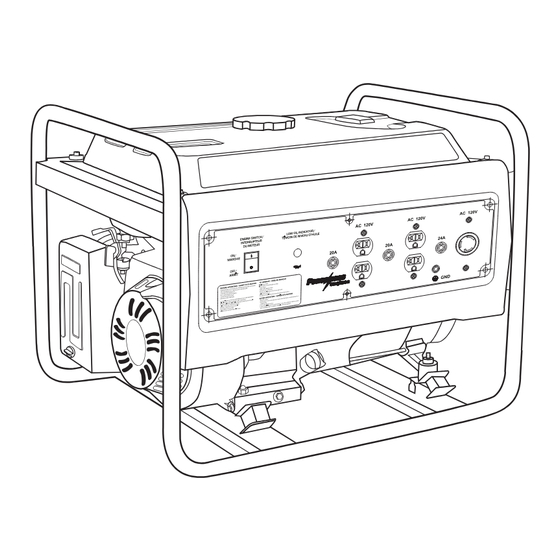
Page 12: Generator Components
GENERATOR COMPONENTS Read this user manual and safety rules before operating your generator. BC3500PS 3500 watt 1. Fuel Tank 2. Fuel Tank Cap 3. Fuel Level Gauge 4. Frame 5. AC Sockets 6. Ground (earth) Terminal 7. Low Oil Indicator 8. - Page 13 GENERATOR COMPONENTS Read this operator’s manual and safety rules before operating your generator. BC4200PS 4200 watt 1. Fuel Tank 2. Fuel Tank Cap 3. Fuel Lever Gauge 4. AC Safety Switch 5. AC Sockets 6. Ground (earth) Terminal 7. Low Oil Alert 8.
-
Page 14: Preparing The Generator
PREPARING THE GENERATORS Preparing the Generator GROUNDING INSTRUCTIONS DANGER Improper connection of the equipment grounding conductor can result in a risk of electrocution. Check with a qualified electrician if you are in doubt as to whether the unit is properly grounded for your local regulations. The ground terminal on the frame can be used to connect the generator to a suitable ground source. The ground path should be made with #8 size wire. Connect the grounding wire securely to the ground terminal. Connect the other end of the wire securely to a suitable ground source. A metal underground water pipe in direct contact with the earth for at least 10 feet can be used as a grounding source. If a pipe is unavail- able, an 8 foot length of pipe or rod may be used as the ground source. The pipe should be 3/4” diameter or larger and the outer surface must be noncorrosive. If a steel or iron rod is used it should be at least 5/8” diameter and if a nonferrous rod is used it should be at least 1/2” diam- eter and be listed as material for grounding. Drive the rod or pipe to a depth of 8’. If a rock bottom is encountered less than 4’ down, bury the rod or pipe in a trench. All electrical tools and appliances operated from this generator, must be properly grounded by use of a third wire or be “Double Insulated”. It is recommended to: 1. Use electrical devices with 3 prong power cords. 2. Use an extension cord with a 3 hole receptacle and a 3 prong plug at the opposite ends to ensure continuity of the ground protection from the generator to appliance. We strongly recommend that all applicable regulations relating to ground- ing specifications be checked and followed. -
Page 15: Pre-Operation Checklist
PRE-OPERATION Pre-Operation ENGINE OIL Before checking or refilling oil, be sure generator is located on stable and level surface with engine stopped. This generator uses SAE 10W30 oil. 1. Remove oil dipstick and check the engine oil level. 2. If oil level is below the lower level line, refill with suitable oil to upper level line. Do not screw in the oil dipstick when checking oil level. 3. Change oil if contaminated. WARNING Always check the level of the engine oil prior to starting the generator. • Failure to do so could cause the engine to seize if the oil is low or empty. High Mark Operating Range Low Mark FUELING WARNING Explosive Fuel! Gasoline is extremely flammable and its vapors can explode if ignited. • DO NOT refuel while smoking or near open flame or other such potential fire hazards. • Store gasoline only in approved containers, in well ventilated, unoccupied buildings and away from sparks or flames. • DO NOT fill the tank while the engine is hot or running, since spilled fuel could ignite if it comes in contact with hot parts or sparks from ignition. • DO NOT start the engine near spilled fuel. • NEVER use gasoline as a cleaning agent. -
Page 16: General Recommendations
PRE-OPERATION WARNING DO NOT overfill the tank, leave room for the fuel to expand. 1. If fuel level is low, refill with unleaded automotive gasoline. 2. Check fuel gauge while filling. 3. When using the generator for the first time or stopping due to the fuel running out, pull the recoil handle several times after filling the tank. GENERAL RECOMMENDATIONS • Purchase gasoline in small quantities and store in clean, approved containers. • To minimize gum deposits in your fuel system and to insure easy starting, do not use gasoline left over from the previous season. • Do not add oil to the gasoline. • Consider adding fuel stabilizer before running or starting the generator. FUEL TYPE • For best results use only clean, fresh, unleaded gasoline with an octane rating of 87 or higher. GASOLINE/ALCOHOL BLENDS Gasohol (up to 10% ethyl alcohol, 90% unleaded gasoline by volume) is approved, as a fuel. Other gasoline/alcohol blends are not approved. GASOLINE/ETHER BLENDS Methyl Tertiary Butyl Ether (MTBE) and unleaded gasoline blends (up to a maximum of 15% MTBE by volume) are approved as a fuel. Other gasoline/ether blends are not approved. CHECK COMPONENT PARTS Check following items before starting engine: 1. Fuel leakage from fuel hose, etc. 2. Bolts and nuts for looseness. 3. Components for damage or breakage. 4. Generator not resting on or against any adjacent wiring. -
Page 17: Check Generator Surroundings
PRE-OPERATION CHECK GENERATOR SURROUNDINGS When listening to the radio near the generator, the radio signal may be disturbed. This may cause distortion or reduced volume from the radio. WARNING Keep area clear of flammables or other hazardous materials. • Keep generator at least 3ft (1m) away from buildings or other structures. • Only operate generators in a dry, well ventilated area. • Keep exhaust pipe clear of foreign objects. • Keep generator away from open flame. No Smoking! • Keep generator on a stable and level surface. • Do not block generator air vents with paper or other material. -
Page 18: Starting The Generator
STARTING YOUR GENERATOR Starting Your Generator RECOIL START CAUTION When starting the engine with the recoil start, set the toggle switch in the “ON” position before pulling the starter handle. 1. Make sure all appliances are disconnected from the generator. 2. Move engine choke switch to the START (ON) position. (When the engine is warm or temperature is high, start engine with the switch in the OFF position). CAUTION Do not connect appliances with defective power cords and/or plugs. Be sure appliances are not connected to generator when starting up. Starting the generator with an appliance connected could result in damage to the generator and/or appliances and personal injury. 3. Pull the recoil starter handle slowly until passing the compression point (resistance will be felt), then return the handle to its original position and pull briskly. Pull Briskly 4. After starting, allow the recoil starter handle to return to its original position with the handle still in your hand. NOTE: If the engine fails to start after several attempts, repeat the starting procedures mentioned above with the engine choke switch placed in the OFF position. -
Page 19: Operation
OPERATION Operation USING ELECTRIC POWER WARNING Risk of electrocution. Make sure that the appliance is switched off before connecting it to the generator. • DO NOT move the generator while it is running. AC APPLICATION 1. Make sure the voltage indicated on the voltmeter is at the normal level (approx. 120V). NOTICE This generator is thoroughly tested and adjusted in the factory. If the generator does not produce the specified voltage, consult your nearest authorized service provider. 2. Turn off the switch(es) of the electrical appliance(s) before connecting to the generator. 3. Insert the plug(s) of the electrical appliance(s) into the receptacle. • Be sure that the total wattage of all connected appliances does not exceed the rated output of the generator. WARNING To take power from the twistlock receptacle, insert the plug into the receptacle, and turn it clockwise to the lock position. • DO NOT put foreign objects into the plug receptacle. 4. Turn on the switch of the appliance. -
Page 20: Wattage Information
OPERATION WATTAGE INFORMATION Some appliances need a “surge” of energy when starting. This means that the amount of electrical power needed to start the appliance may exceed the amount needed to maintain its use. Electrical appliances and tools normally come with a label indicating voltage, cycles / Hz, amperage (amps) and electrical power needed to run the appliance or tool. Check with your nearest dealer or service provider with questions regard- ing power surge of certain appliances or power tools. • Electrical loads such as incandescent lamps and hot plates require the same wattage to start as is needed to maintain use. • Loads such as fluorescent lamps require 1.2 to 2 times the indicated wattage during start-up. • Loads for mercury lamps require 2 to 3 times the indicated wattage during start-up. • Electrical motors require a large starting current. Power requirements depend on the type of motor and its use. Once enough “surge” is attained to start the motor, the appliance will require only 30% to 50% of the wattage to continue running. • Most electrical tools require 1.2 to 3 times their wattage for running under load during use. For example, a 5000 watt generator can power a 1800 to 4000 watt electrical tool. • Loads such as submersible pumps and air compressors require a very large force to start. They need 3 to 5 times the normal running wattage in order to start. For example, a 5000 watt generator would only be able to drive a 1000 to 7000 watt pump. To determine the total wattage required to run a particular electrical appliance or tool, multiply the voltage figure of the appliance / tool by the amperage (amps) figure of same. The voltage and amperage (amps) information can be found on a name plate which is normally attached to electrical appliances and tools. CAUTION If an electric motor fails to start or reach running speed, turn off the appliance or tool immediately to avoid equipment damage. Always check the requirements of the tool or appliance being used compared to the rated output of the generator. -
Page 21: Spark Arrester
OPERATION SPARK ARRESTER The spark arrester must be cleaned regularly to keep it functioning as designed. A clogged spark arrester: • Prevents the flow of exhaust gas • Reduces engine output • Increases fuel consumption • Makes starting difficult CAUTION If engine has been running, the muffler and the spark arrester will be very hot. Allow the muffler to cool before cleaning the spark arrester. HOW TO REMOVE THE SPARK ARRESTER 1. Remove the flange bolts from the muffler cover and remove the muffler cover. 2. Remove the special screw from the spark arrester and remove the spark arrester from the muffler. CLEAN THE SPARK ARRESTER SCREEN 1. Use a brush to remove carbon deposits from the spark arrester screen. Be careful to avoid damaging the screen. 2. The spark arrester must be free of breaks and holes. Replace the spark arrester if it is damaged. 3. Install the spark arrester, and muffler protector in the reverse order of disassembly. If you have any problems with the operation of your generator, please call the generator help line at 1-855-850-6668. If calling for assistance, please have the model and serial number available. -
Page 22: Stopping The Generator
STOPPING THE GENERATOR Stopping The Generator 1. Turn off the power switch of the electric equipment and unplug the cord from receptacle of the generator. 2. Allow the engine about 3 minutes to cool down without load before stopping. 3. Push the engine switch to the OFF position. 4. Push the main switch to the OFF position. OIL SENSOR The oil sensor detects a drop in oil level in the crankcase and automatically stops the engine when the oil level drops below a predetermined level. When the engine has stopped automatically, turn off the generator, and check the oil level. Refill engine oil to the upper level as instructed and restart the engine. CAUTION DO NOT remove oil sensor probe when refilling with oil. Remove oil filler cap on the opposite side of carburetor. -
Page 23: Troubleshooting
TROUBLESHOOTING Troublshooting TROUBLESHOOTING CHART If you are experiencing a problem that is not listed in this chart, or have checked all the possible cause listed and you are still experiencing the problem, see your authorized dealer. Problem Cause Correction Engine will not start 1. Check if engine switch is off. 1. Turn engine switch to the Choke position. 2. Fuel Tank empty. 2. Fill tank ensuring you do not overfill. 3. -
Page 24: Maintenance
MAINTENANCE Maintenance MAINTENANCE SCHEDULE CAUTION Make sure the engine is stopped before starting any maintenance, servicing or repair. NOTE: It is recommended to use ear protection when performing operation, maintenance and repair of the generator. Maintenance, replacement or repair of the emission control devices and systems must be performed by an authorized service provider. DAILY INSPECTION Before running the generator, check the following service items: • Safe surroundings. • Leakage of gasoline and engine oil. • Clean engine oil. • AC receptacle for damage. • Enough gasoline. • Excessive vibration, noise. • Loose or broken bolts, nuts or shields. • Clean air element. PERIODIC MAINTENANCE Periodic maintenance is vital to safe and efficient operation of your generator. -
Page 25: Changing Engine Oil
MAINTENANCE CHANGING ENGINE OIL Change oil after the first 20 hours of operation. Thereafter it should be changed every 100 hours. This generator uses SAE 10W30 oil. 1. Place an oil pan beneath the unit. Drain oil by removing the drain plug and the oil filler cap while the engine is warm, but not hot. 2. Reinstall the drain plug and fill the engine with oil until it reaches the upper level on the oil filler cap. 3. Dispose of used oil according to local zoning or environmental regulations. SERVICING THE AIR CLEANER Maintaining the air cleaner in proper condition is very important. Dirt induced through improperly installed, improperly serviced or inadequate elements damages and wears out engines. Always keep the element clean. Never run the generator without the air filter element. 1. Unhook the cover and remove the cleaner element. 2. Urethane foam: Wash the element with fresh water. Squeeze out the water then dry the element. (Do not twist.) CLEANING AND GAPPING SPARK PLUG If the plug is contaminated with carbon, remove the carbon using a plug cleaner or wire brush. Use NGK BPR6ES or equivalent. Adjust the electrode gap to 0.6 to 0.7 mm (0.024 to 0.028 in). CLEANING FUEL STRAINER Dirt and water in the fuel are removed by the fuel strainer. -
Page 26: Transporting
TRANSPORTING 1. Check the fuel (gasoline), engine oil and air cleaner. 2. Start engine. 3. With appliance such as lighting activated, run the engine for over ten minutes. 4. Check the following items: • Engine running properly. • Adequate output. • Engine switch normally operated. • No leakage of engine oil and fuel (gasoline). Transporting TRANSPORTING When transporting the generator, make sure that the fuel (gasoline) should be drained from the tank. WARNING To prevent fuel spillage due to the vibration and impact, never transport the generator with fuel (gasoline) in the tank. Secure the tank cap. To avoid the risk of the gasoline flammability, never leave the generator in an area exposed to direct sunlight or high temperatures for a long period time. Keep the fuel in an approved storage tank when transporting. 1. Turn the engine switch to the STOP position. 2. Drain the fuel from the tank. 3. Tighten the tank cap. CAUTION DO NOT place any heavy objects on the generator. Select and place the generator in the proper position of the transport vehicle so that the generator will not move or fall down. Secure the generator if necessary. -
Page 27: Storage
STORAGE Storage PREPARATION FOR STORAGE The following procedures should be followed prior to storage of your generator for periods of 6 months or longer. 1. Drain fuel from fuel tank carefully by disconnecting the fuel line. Gasoline left in the fuel tank will eventually deteriorate making engine starting difficult. Add fuel stabilizer to fuel tank. 2. Remove the drain screw of the carburetor. 3. Change engine oil. 4. Check for loose bolts and screws, tighten them if necessary. 5. Clean generator thoroughly with clean cloth. NEVER USE WATER TO CLEAN GENERATOR. 6. Pull recoil starter handle until resistance is felt, leaving handle in that position. 7. Store generator in a well ventilated, low humidity area. -
Page 28: Warranty
WARRANTY Warranty CALIFORNIA EMISSION CONTROL WARRANTY STATEMENT The California Air Resources Board, the United States Environmental Protection Agency and A-iPOWER, are pleased to explain the emission control system warranty on your 2015-2016 model year small off-road engine/equipment. In the United States and California, new small off-road engine/equipment must be designed, built and equipped to meet the State’s stringent anti smog standards. AIPOWER must warrant the emission control system on your small off-road engine/equipment for the periods of time listed below provided there has been no abuse, neglect or improper maintenance of your small off-road engine/equipment. Your emission control system may include parts such as the carburetor or fuel injection system, the ignition system, catalytic converter, fuel tanks, fuel lines, fuel caps, valves, canisters, filters, vapor hoses, clamps, connectors, belts, and other associated emissionrelated components. For engines less than or equal to 80 cc, only the fuel tank is subject to the evaporative emission control warranty requirements of this section (California only). Where a warrantable condition exists, A-IPOWER will repair your small offroad engine/equipment at no cost to you including diagnosis, parts and labor. MANUFACTURER’S WARRANTY COVERAGE This Emissions Control System is warranted for two years. If any emission-related part on your engine/equipment is defective, the part will be repaired or replaced by AIPOWER. OWNER’S WARRANTY RESPONSIBILITIES As the small off-road engine/equipment owner, you are responsible for the performance of the required maintenance listed in your owner’s manual. A-IPOWER recommends that you retain all receipts covering maintenance on your small off-road engine/equipment, but A-IPOWER cannot deny warranty solely for the lack of receipts or for your failure to ensure the performance of all scheduled maintenance. - Page 29 WARRANTY contact Senci Power USA Inc at 1-855-888-3598 or support@a-ipower. com. DEFECTS WARRANTY REQUIREMENTS a. The warranty period begins on the date the engine/equipment is delivered to an ultimate purchaser. b. General Emissions Warranty Coverage. A-IPOWER warrants to the ultimate purchaser and each subsequent owner that the engine/ equipment is: 1. Designed, built, and equipped so as to conform with all applicable regulations adopted by the Air Resources Board; and 2. Free from defects in materials and workmanship that causes the failure of a warranted part for a period of two years. c. The warranty on emissions-related parts will be interpreted as follows: 1. Any warranted part that is not scheduled for replacement as required maintenance in the written instructions required by subsection (d) must be warranted for the warranty period defined in Subsection (b) (2). If any such part fails during the period of warranty coverage, it must be repaired or replaced by A-IPOWER according to Subsection (4) below. Any such part repaired or replaced under the warranty must be warranted for the remaining warranty period. 2. Any warranted part that is scheduled only for regular inspection in the written instructions required by subsection (d) must be warranted for the warranty period defined in Subsection (b) (2) . A statement in such written instructions to the effect of “repair or replace as necessary” will not reduce the period of warranty must be warranted for the remaining warranty period. 3. Any warranted part that is scheduled for replacement as required maintenance in the written instructions required by subsection (d) must be warranted for the period of time prior to the first scheduled replacement point for that part. If the part fails prior to the first scheduled replacement, the part must be repaired or replaced by AIPOWER according to Subsection (4) below. Any such part repaired or replaced under warranty must be warranted for the remainder of the period prior to the first scheduled replacement point for the part. 4. Repair or replacement of any warranted part under the warranty must be performed at no charge to the owner at a warranty station. 5. Notwithstanding the provisions of Subsection (4) above, warranty services or repairs must be provided at all AIPOWER distribution ...
- Page 30 WARRANTY part. 8. Throughout the emissions warranty period defined in Subsection (b) (2), AIPOWER must maintain a supply of warranted parts sufficient to meet the expected demand for such parts. 9. Any replacement part may be used in the performance of any warranty maintenance or repairs and must be provided without charge to the owner. Such use will not reduce the warranty obligations of A-IPOWER. maintenance or repairs and must be provided without charge to the owner. Such use will not reduce the warranty obligations of A-IPOWER. 10. Add-on or modified parts that are not exempted by the Air Resources Board may not be used. The use of any non-exempted add-on or modified parts will be grounds for disallowing a warranty claim. A-IPOWER will not be liable to warrant failures of warranted parts caused by the use of a nonexempted add-on or modified part. 11. A-IPOWER issuing the warranty shall provide any documents that describe that manufacturer’s warranty procedures or policies within five working days of request by the Air Resources Board. d. Emission Warranty Parts List for exhaust (for all displacements). 1. Fuel Metering System (i) Carburetor and internal parts (and/or pressure regulator or fuel injection system). (ii) Air/fuel ratio feedback and control system. (iii) Cold start enrichment system. 2. Air Induction System (i) Controlled hot air intake system. (ii) Intake manifold. (iii) Air filter. 3. Ignition System (i) Spark Plugs. (ii) Magneto or electronic ignition system. (iii) Spark advance/retard system. 4. Exhaust Gas Recirculation (EGR) System (i) EGR valve body, and carburetor spacer if applicable. (ii) EGR rate feedback and control system. 5. Air Injection System (i) Air pump or pulse valve. (ii) Valves affecting distribution of flow. (iii) Distribution manifold.
- Page 31 WARRANTY 6. Catalyst or Thermal Reactor System (i) Catalytic converter. (ii) Thermal reactor. (iii) Exhaust manifold. 7. Particulate Controls (i) Traps, filters, precipitators, and any other device used to capture particulate emissions. 8. Miscellaneous Items Used in Above Systems (i) Electronic controls. (ii) Vacuum, temperature, and time sensitive valves and switches. e. Emission Warranty Parts List for Evap less than or equal to 80cc. (i) Fuel Tank. f. Emission Warranty Parts List for Evap greater than 80cc. 1. Fuel Metering System (i) Fuel Tank. 2. Miscellaneous Items Used in Above Systems (i) Fuel caps, valves, canisters, filters, vapor, hoses, clamps, connectors, belts, and and assemblies. A-IPOWER will furnish with each new engine/equipment written instructions for the maintenance and use of the engine/equipment by the owner.
- Page 32 If you need assistance with the assembly or operation of your Generator please call 1-855-850-6668...
Need help?
Do you have a question about the BC3500PS and is the answer not in the manual?
Questions and answers