Advertisement
Quick Links
v-
\
\
\
I'
,
\
,
u
1
:'---","--.,...--'-
..
~\_",---
;
Jt;£
S~1t
iP-l-iO-N
-:--,-~
i!
"---'!!' -
14
-~--'-'~~- ,,~---
. _
~:.,
"
~"
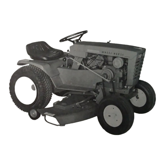
This mower
i~
designed to fit on
~5~
1076,
whe4with the long hub extension goes
~r,.~~t~.
1276, 1057, 1257, 1077, 1277, 1067, 1267, Charger
gagl:
wheel support. Secure in place with the shoul-
and Raider tractors.
der bolts and the two %-16 jam nuts, see Fig. II.
The 8-3111 or PT·6 Power TOke-Off unit is used on
Slide the pivot arm assembly on to the shaft of the,
all the madel, Ii,ted above ex<opt the made I
10'~....
mawe, .upport a' in
Fig. "
and .. ,u,e in pla<o
w~
On this model....a PT-7 is used.
r
4736 "E" ring. Remove the cam arm
ass~f'bly
672
,
from the pivot arm for future assembly. -.ttach t -- '\
'~
-
~"'"
.
915663-4
NUT -
3/8-16
ELASTIC STOP
MW4SM
6.718
ASS'V LATCH &
SHAFT
13
MOUNTING PlATE
S-"l"ORT. STUD
ASS EM 8'l Y
933512-4
HAIRPIN COTTER
Fig. I -
To identify the loose parts, refer to Fig.
I.
Install-
the wheels to the mower. Note that the side of the
lift rod 6699 to the ,mower support. It snouleJ be put:
through from the right side of the lift rod plate as-
shown in Fig. VII. Hold in place with the hairpin
cotter. Part No. 933504-4. Slide the lift stud 6739 on
the lift rod and thread on a %-16 elastic stop nut as
shown in Fig. VII.
Advertisement

Related Manuals for Wheel Horse 5-1481


Summary of Contents for Wheel Horse 5-1481
- Page 5 3DJH RI :KHHO +RUVH 6HUYLFH %XOOHWLQV ,VVXHG 0DUFK 5RWDU\ 0RZHUV 0RGHOV 5/ 3UHYLRXV 7DEOH RI &RQWHQWV 1H[W 0RZHU ,QVWDOODWLRQ 5HPRYDO 7R IDFLOLWDWH WKH LQVWDOODWLRQ DQG UHPRYDO RI WKH PRZHUV ZH VXJJHVW WKDW WKH FDP DUP DVVHPEO\ EH LQVWDOOHG RQ WKH IRRW UHVW VXSSRUW ZLWK WKH VKDIW SRLQWLQJ RXWZDUG ,QVWDOODWLRQ RI WKH FDP DUP LQ WKLV SRVLWLRQ DOORZV WKH PRZHU WR EH UHPRYHG DQG LQVWDOOHG ZLWKRXW GLVWXUELQJ WKH IRRW UHVW DV XVHG RQ WKH &KDUJHU DQG 5DLGHU PRGHOV +HLJKW &RQWURO...
- Page 6 3DJH RI :KHHO +RUVH 6HUYLFH %XOOHWLQV ,VVXHG $SULO 5RWDU\ 0RZHU &KDQJHV 0RGHOV 3UHYLRXV 7DEOH RI &RQWHQWV 1H[W 7R LQVXUH EHWWHU WUDFWRU WR PRZHU EHOW DOLJQPHQW PLQRU FKDQJHV KDYH EHHQ LQFRUSRUDWHG LQ WKH DERYH PRZHUV 7KHVH FKDQJHV DUH GHVFULEHG EHORZ DQG DUH DSSOLFDEOH ZKHQ PRXQWLQJ WKHVH PRZHUV RQ DOO ORQJ IUDPH WUDFWRU PRGHOV 0RGHO 0RZHU...
- Page 7 3DJH RI :KHHO +RUVH 6HUYLFH %XOOHWLQV ,VVXHG 0DUFK 0RZHU 6SLQGOH 6HUYLFH ,QIRUPDWLRQ DQG 3ULRU 0RZHUV 3UHYLRXV 7DEOH RI &RQWHQWV 1H[W 7+,6 %8//(7,1 683(56('(6 %8//(7,1 $ ,668(' $35,/ 7R $OO 'HDOHUV 6XEMHFW 7KH IROORZLQJ LQIRUPDWLRQ LV VXSSOLHG WR DVVLVW \RX LQ LGHQWLI\LQJ DYDLODEOH VHUYLFH SDUWV 127( $OO PRZHUV XVLQJ WKH VSLQGOHV OLVWHG EHORZ FDQ EH FRQYHUWHG WR WKH ODWHVW JUHDVHDEOH W\SH UHIHU WR 6HUYLFH %XOOHWLQ...
- Page 8 3DJH RI 3DUW 1R 'HVFULSWLRQ +RXVLQJ 1HHGOH %HDULQJ 7KUXVW :DVKHU %DOO %HDULQJ 6QDS 5LQJ 6KDIW 6QDS 5LQJ +RXVLQJ 6KDIW :KHQ EXLOGLQJ D FRPSOHWH DVVHPEO\ IURP SDUWV ILOO KRXVLQJ ZLWK RXQFHV RI PXOWL SXUSRVH OLWKLXP EDVH JUHDVH %XOOHWLQ LV *UHDWO\ 5HYLVHG WR 8SGDWH ,QIRUPDWLRQ 6SLQGOH 6KDIW 1R ORQJHU DYDLODEOH 50 0RZHU...
- Page 9 3DJH RI 6SHFLDO :DVKHU 6SLQGOH 6KDIW 1R ORQJHU DYDLODEOH 0RZHUV 50 UHSODFHV VKDIW 3DUW 1XPEHUV DQG DVVHPEO\ IROORZ 3DUW 1R 'HVFULSWLRQ 6KDIW 6QDS 5LQJ %HORZ %DOO %HDULQJ LQ VQDS ULQJ JURRYH :DVKHU %HWZHHQ 3XOOH\ %DOO %HDULQJ ILOH ( ?+WPO?6(59?EOWQ?ZK?D?ZDB E KWP...
Need help?
Do you have a question about the 5-1481 and is the answer not in the manual?
Questions and answers