Table of Contents
Advertisement
Available languages
Available languages
Quick Links
INSTALLATION INSTRUCTIONS
IN-LINE SMART KIT
Installation Instructions
For questions about features, operation/performance, parts, accessories or service, call: 1-800-253-1301
or visit our website at www.whirlpool.com
In Canada, call 1-800-807-6777 or visit our website at www.whirlpool.ca
INSTRUCTIONS D'INSTALLATION
VENTILATEUR DÉPORTÉ INTELLIGENT
Instructions d'installation
Au Canada, pour assistance, installation ou service, composer le 1-800-807-6777
ou visiter notre site Web à www.whirlpool.ca
Table of Contents/Table des matières............................................................................. 2
IMPORTANT: READ AND SAVE THESE INSTRUCTIONS.
FOR RESIDENTIAL USE ONLY.
IMPORTANT : LIRE ET CONSERVER CES INSTRUCTIONS.
POUR UTILISATION RÉSIDENTIELLE UNIQUEMENT.
LIB0100831A/W10708303A
Advertisement
Table of Contents

Related Manuals for Whirlpool W10692945


Summary of Contents for Whirlpool W10692945
- Page 1 IN-LINE SMART KIT Installation Instructions For questions about features, operation/performance, parts, accessories or service, call: 1-800-253-1301 or visit our website at www.whirlpool.com In Canada, call 1-800-807-6777 or visit our website at www.whirlpool.ca INSTRUCTIONS D’INSTALLATION VENTILATEUR DÉPORTÉ INTELLIGENT Instructions d’installation Au Canada, pour assistance, installation ou service, composer le 1-800-807-6777 ou visiter notre site Web à...
-
Page 2: Table Of Contents
TABLE OF CONTENTS TABLE DES MATIÈRES RANGE HOOD SAFETY ..............2 SÉCURITÉ DE LA HOTTE DE CUISINIÈRE........32 INSTALLATION REQUIREMENTS ..........4 EXIGENCES D’INSTALLATION ...........34 Tools and Parts ................4 Outillage et pièces..............34 Location Requirements..............4 Exigences d’emplacement............34 Venting Requirements..............5 Exigences concernant l’évacuation ...........35 Electrical Requirements ...............6 Spécifications électriques ............36 INSTALLATION INSTRUCTIONS ..........6 INSTRUCTIONS D’INSTALLATION..........36... - Page 3 IMPORTANT SAFETY INSTRUCTIONS WARNING: WARNING: TO REDUCE THE RISK OF FIRE, ELECTRIC TO REDUCE THE RISK OF A RANGE TOP GREASE FIRE: SHOCK, OR INJURY TO PERSONS, OBSERVE THE FOLLOWING: Never leave surface units unattended at high settings. ■ Boilovers cause smoking and greasy spillovers that may Use this unit only in the manner intended by the ■...
-
Page 4: Installation Requirements
INSTALLATION REQUIREMENTS ®† 1 - T10 Torx adapter Tools and Parts 1 - T20 ® Torx ® adapter Gather the required tools and parts before starting installation. Read 1 - Plastic wire clip and follow the instructions provided with any tools listed here. 4 - 5 x 45 mm mounting screws Tools needed 3 - 2.9 x 13 mm mounting screws... -
Page 5: Venting Requirements
Venting Requirements Vent system must terminate to the outdoors. NOTE: Plywood may be used as a mounting base to span open areas between ceiling joists and rafters. If used, be sure to use Do not terminate the vent system in an attic or other enclosed plywood capable of supporting 25 Ib (11.3 kg). -
Page 6: Electrical Requirements
Electrical Requirements Observe all governing codes and ordinances. If the house has aluminum wiring, follow the procedure below: Ensure that the electrical installation is adequate and in conformance with National Electrical Code, ANSI/NFPA 70 (latest 1. Connect a section of solid copper wire to the pigtail edition), or CSA Standards C22.1-94, Canadian Electrical Code, leads. -
Page 7: Install In-Line Smart Kit Kvwb40Ds Series Range Hoods
Install In-Line Smart Kit KVWB40DS Series Range Hoods 4. Using the T10 Torx ® adapter, remove the 4 screws from the Remove Blower Motor from Range Hood Housing blower motor cover plate. Remove the cover plate from the motor and set it aside. WARNING Electrical Shock Hazard Disconnect power before servicing. - Page 8 7. Push on the blower motor to disengage the two spring tabs 3. Install the vent transition without a backdraft damper to the from the keyhole slots in the top of the range hood housing. bottom of the in-line base. Use the T10 Torx ®...
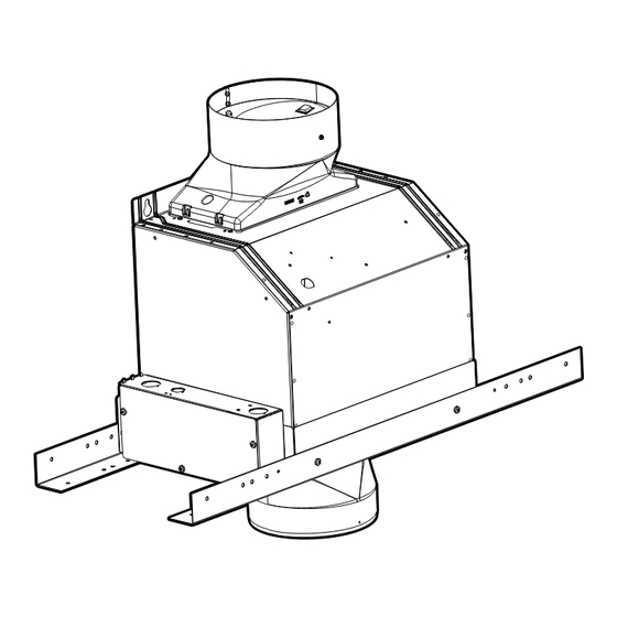
- Page 9 8. Connect the 9-pin connector from the blower motor to the Install In-Line Smart Kit 9-pin connector inside the in-line base. The In-Line Smart Kit must be installed to a secure structure of the roof, ceiling, wall, or floor. The In-Line Smart Kit may also be installed into a new or existing frame construction.
-
Page 10: Complete Installation
Complete Installation Determine and make all necessary cuts and drill holes for the 7. Install the UL listed or CSA approved strain reliefs (3) in the vent system. range hood and In-Line Smart kit electrical knockouts. IMPORTANT: When cutting or drilling into the ceiling or wall, be 8. -
Page 11: Make Electrical Connection
Make Electrical Connection WARNING Connect Range Hood and In-Line Smart Kit 1. Measure the distance between the In-Line Smart Kit and the range hood terminal box. Electrical Shock Hazard Disconnect power before servicing. Replace all parts and panels before operating. Failure to do so can result in death or electrical shock. -
Page 12: Install In-Line Smart Kit Kvub60Ds Series Range Hoods
Electrical Connection Range Hood Connect In-Line Smart Kit WARNING Electrical Connection In-Line Smart Kit 1. Use a UL listed or CSA approved wire connector to connect the black wires together. 2. Use a UL listed or CSA approved wire connector to connect the white wires together. - Page 13 4. Using the T10 Torx ® adapter, remove the 4 screws from the 7. Push on the blower motor to disengage the 2 spring tabs blower motor cover plate. Remove the cover plate from the from the keyhole slots in the top of the range hood housing. motor and set it aside.
- Page 14 11. Install the metal terminal box supplied with the In-Line Smart 3. Install the vent transition without a backdraft damper to the ® Kit to the top of the range hood using 2 - 3.5 x 6.5 mm bottom of the in-line base. Use the T10 Torx adapter and mounting screws.
- Page 15 8. Connect the 9-pin connector from the blower motor to the Install In-Line Smart Kit 9-pin connector inside the in-line base. The In-Line Smart Kit must be installed to a secure structure of the roof, ceiling, wall, or floor. The In-Line Smart Kit may also be installed into a new or existing frame construction.
-
Page 16: Complete Installation
Complete Installation Determine and make all necessary cuts and drill holes for the 7. Install the UL listed or CSA approved strain reliefs (3) in the vent system. range hood and In-Line Smart kit electrical knockouts. IMPORTANT: When cutting or drilling into the ceiling or wall, be 8. -
Page 17: Make Electrical Connection
Make Electrical Connection 4. Connect together the set of 8 wires in the range hood WARNING terminal box. Electrical Shock Hazard Disconnect power before servicing. Replace all parts and panels before operating. Failure to do so can result in death or electrical shock. Connect Range Hood and In-Line Smart Kit Connect In-Line Smart Kit 1. -
Page 18: Install In-Line Smart Kit Jxw85Ds, Jxi85Ds, Kvwb60Ds, And Kvib60Ds Series Range Hoods
Install In-Line Smart Kit JXW85DS, JXI85DS, KVWB60DS, and KVIB60DS Series Range Hoods ® 4. Using the T10 Torx adapter remove the screws securing the Remove Blower Motor from Range Hood Housing filter retainer panel to the range hood. See the following illustrations for screw locations and numbers. - Page 19 5. Disconnect the blower motor from the range hood wiring. 8. Using the T20 ® Torx ® adapter with a long extension, remove Using a flat blade screwdriver, and press down on the top clip the 4 screws that secure the blower motor to the range hood of the 9-pin electrical connector while pressing the bottom housing and set them aside.
- Page 20 14. Remove the 2 electrical knockouts from the top of the range 18. Run the 3 electrical power wires (black, white and green) and hood electrical box and install a UL listed or CSA approved the cover plate ground wire (green) through the small plastic strain relief into the front knockout.
- Page 21 22. Install the metal terminal box suppled with the In-Line Smart 3. Install the vent transition without a backdraft damper to the ® Kit to the top of the range hood electrical box. Use bottom of the in-line base. Use the T10 Torx adapter and 2 - 3.5 x 6.5 mm screws to secure the terminal box.
- Page 22 8. Connect the 9-pin connector from the blower motor to the Install In-Line Smart Kit 9-pin connector inside the in-line base. The In-Line Smart Kit must be installed to a secure structure of the roof, ceiling, wall, or floor. The In-Line Smart Kit may also be installed into a new or existing frame construction.
-
Page 23: Complete Installation
Complete Installation Determine and make all necessary cuts and drill holes for the 7. Connect the vent system to the vent transition on the range vent system. hood. Connect the vent system to the vent transition located on the bottom In-Line Smart Kit. Use clamps and metal duct IMPORTANT: When cutting or drilling into the ceiling or wall, be tape to seal all joints. -
Page 24: Make Electrical Connection
Make Electrical Connection 5. Connect together the set of 8 wires in the range hood WARNING terminal box. Electrical Shock Hazard Disconnect power before servicing. Replace all parts and panels before operating. Failure to do so can result in death or electrical shock. Connect Range Hood and In-Line Smart Kit Connect In-Line Smart Kit 1. -
Page 25: Install In-Line Smart Kit Wvw75Uc And Wv175Uc Series Range Hoods
Install In-Line Smart Kit WVW75UC and WV175UC Series Range Hoods 5. Remove the 2 screws securing the insulating retainer to the Remove Blower Motor from Range Hood Housing blower motor and set them aside. 6. Disconnect the blower motor from the range hood wiring. Using a flat blade screwdriver, and press down on the top clip WARNING of the 9-pin electrical connector while pressing the bottom... - Page 26 9. Remove the 2 electrical knockouts from the top of the range 13. Run the 3 electrical power wires (black, white and green) and hood electrical box and install a UL listed or CSA approved the cover plate ground wire (green) through the small plastic strain relief into the front knockout.
- Page 27 17. Install the metal terminal box suppled with the In-Line Smart 3. Install the vent transition without a backdraft damper to the ® Kit to the top of the range hood electrical box. Use bottom of the in-line base. Use the T10 Torx adapter and 2 - 3.5 x 6.5 mm screws to secure the terminal box.
- Page 28 8. Connect the 9-pin connector from the blower motor to the Install In-Line Smart Kit 9-pin connector inside the in-line base. The In-Line Smart Kit must be installed to a secure structure of the roof, ceiling, wall, or floor. The In-Line Smart Kit may also be installed into a new or existing frame construction.
-
Page 29: Complete Installation
Complete Installation Determine and make all necessary cuts and drill holes for the 7. Connect the vent system to the vent transition on the range vent system. hood. Connect the vent system to the vent transition located on the bottom In-Line Smart Kit. Use clamps and metal duct IMPORTANT: When cutting or drilling into the ceiling or wall, be tape to seal all joints. -
Page 30: Make Electrical Connection
Make Electrical Connection 5. Connect together the set of 8 wires in the range hood WARNING terminal box. Electrical Shock Hazard Disconnect power before servicing. Replace all parts and panels before operating. Failure to do so can result in death or electrical shock. Connect Range Hood and In-Line Smart Kit Connect In-Line Smart Kit 1. -
Page 31: Wiring Diagram
WIRING DIAGRAM YL/GN YL/GN SE14CA... -
Page 32: Sécurité De La Hotte De Cuisinière
SÉCURITÉ DE LA HOTTE DE CUISINIÈRE Votre sécurité et celle des autres est très importante. Nous donnons de nombreux messages de sécurité importants dans ce manuel et sur votre appareil ménager. Assurez-vous de toujours lire tous les messages de sécurité et de vous y conformer. Voici le symbole d’alerte de sécurité. - Page 33 IMPORTANTES INSTRUCTIONS DE SÉCURITÉ AVERTISSEMENT : AVERTISSEMENT : POUR RÉDUIRE LE RISQUE POUR MINIMISER LE RISQUE D'INCENDIE, CHOC ÉLECTRIQUE OU DOMMAGES D'UN FEU DE GRAISSE SUR LA CUISINIÈRE : CORPORELS, RESPECTER LES INSTRUCTIONS Ne jamais laisser un élément de surface fonctionner à ■...
-
Page 34: Exigences D'installation
EXIGENCES D’INSTALLATION 1 adaptateur Torx ®† Outillage et pièces 1 adaptateur Torx ® ® Rassembler les outils et pièces nécessaires avant d’entreprendre 1 attache-câble en plastique l’installation. Lire et observer les instructions fournies avec chacun 4 vis de montage de 5 x 45 mm des outils de la liste ci-dessous. -
Page 35: Exigences Concernant L'évacuation
Exigences concernant l’évacuation Le système doit évacuer l’air à l’extérieur. REMARQUE : Il est possible d’utiliser du contreplaqué comme base de montage dans les zones vides entre solives et chevrons. Ne pas terminer le circuit d’évacuation dans un grenier ou Dans un tel cas, le contreplaqué... -
Page 36: Spécifications Électriques
Spécifications électriques Observer les dispositions de tous les codes et règlements en Si le domicile possède un câblage en aluminium, suivre la vigueur. procédure ci-dessous : S’assurer que l’installation électrique est correcte et qu’elle 1. Raccorder une portion de câble en cuivre massif aux satisfait aux exigences de la plus récente édition de la norme conducteurs de raccordement. -
Page 37: Installation Du Ventilateur Déporté Intelligent Hottes Série Kvwb40Ds
Installation du ventilateur déporté intelligent Hottes série KVWB40DS ® 4. À l’aide de l’adaptateur Torx T10, ôter les 4 vis du couvercle Dépose du moteur du ventilateur de la caisse de la hotte du moteur du ventilateur. Retirer le couvercle du moteur et le mettre de côté. - Page 38 7. Pousser le moteur du ventilateur pour dégager les deux 3. Installer le raccord de transition sans clapet anti-reflux du languettes à ressort des orifices en trou de serrure situés en côté inférieur de la base du ventilateur déporté. À l’aide de haut de la caisse de la hotte.
- Page 39 8. Brancher le connecteur à 9 broches du moteur du ventilateur à Installation du ventilateur déporté intelligent son homologue à l’intérieur de la base du ventilateur déporté. Le ventilateur déporté intelligent doit être fixé à une structure bien solide de la toiture, du plafond, du mur ou du sol. Il est également possible d’installer le ventilateur déporté...
-
Page 40: Achever L'installation
Achever l’installation Déterminer et exécuter les découpes et trous nécessaires au 7. Installer les 3 serre-câble homologués UL ou CSA dans les passage du circuit d’évacuation. opercules de la hotte et du ventilateur déporté intelligent. IMPORTANT : Lors des opérations de découpe et de perçage 8. -
Page 41: Raccordement Électrique
Raccordement électrique Raccordement de la hotte et du ventilateur déporté AVERTISSEMENT intelligent 1. Mesurer la distance entre le ventilateur déporté intelligent et le boîtier de raccordement de la hotte. Risque de choc électrique Déconnecter la source de courant électrique avant l'entretien. -
Page 42: Installation Du Ventilateur Déporté Intelligent Hottes Série Kvub60Ds
Raccordement électrique de la hotte Raccordement du ventilateur déporté intelligent AVERTISSEMENT Raccordement électrique du ventilateur déporté intelligent 1. Utiliser un connecteur de fils (homologation UL ou CSA) pour raccorder les deux conducteurs noirs. 2. Utiliser un connecteur de fils (homologation UL ou CSA) pour raccorder les deux conducteurs blancs. - Page 43 4. À l’aide de l’adaptateur Torx ® T10, ôter les 4 vis du couvercle 7. Pousser le moteur du ventilateur pour dégager les deux du moteur du ventilateur. Retirer le couvercle du moteur et le languettes à ressort des orifices en trou de serrure situés en mettre de côté.
- Page 44 11. Fixer le boîtier de raccordement métallique fourni avec le 3. Installer le raccord de transition sans clapet anti-reflux du ventilateur déporté intelligent sur le dessus de la hotte au côté inférieur de la base du ventilateur déporté. À l’aide de moyen des 2 vis de 3,5 x 6,5 mm.
- Page 45 8. Brancher le connecteur à 9 broches du moteur du ventilateur Installation du ventilateur déporté intelligent à son homologue à l’intérieur de la base du ventilateur déporté. Le ventilateur déporté intelligent doit être fixé à une structure bien solide de la toiture, du plafond, du mur ou du sol. Il est également possible d’installer le ventilateur déporté...
-
Page 46: Achever L'installation
Achever l’installation Déterminer et exécuter les découpes et trous nécessaires au 7. Installer les 3 serre-câble homologués UL ou CSA dans les passage du circuit d’évacuation. opercules de la hotte et du ventilateur déporté intelligent. IMPORTANT : Lors des opérations de découpe et de perçage 8. -
Page 47: Raccordement Électrique
Raccordement électrique 4. Connecter les 8 conducteurs dans le boîtier de raccordement AVERTISSEMENT de la hotte. Risque de choc électrique Déconnecter la source de courant électrique avant l'entretien. Replacer pièces et panneaux avant de faire la remise en marche. Le non-respect de ces instructions peut causer un décès ou un choc électrique. -
Page 48: Installation Du Ventilateur Déporté Intelligent Hottes Série Jxw85Ds, Jxi85Ds, Kvwb60Ds Et Kvib60Ds
Installation du ventilateur déporté intelligent Hottes série JXW85DS, JXI85DS, KVWB60DS et KVIB60DS ® 4. À l’aide de l’adaptateur Torx T10, retirer les vis qui Dépose du moteur du ventilateur de la caisse de la hotte maintiennent le panneau de retenue du filtre à la hotte. Voir les illustrations suivantes pour connaître l’emplacement et le nombre de vis. - Page 49 5. Déconnecter le moteur du ventilateur du câblage de la hotte. 8. À l’aide de l’adaptateur Torx ® ® équipé d’une rallonge, ôter À l’aide d’un tournevis à lame plate, appuyer sur la languette les 4 vis qui maintiennent le moteur du ventilateur à la caisse supérieure du connecteur électrique à...
- Page 50 14. Ôter les 2 opercules arrachables en haut du coffret électrique 18. Faire passer les 3 conducteurs d’alimentation (noir, blanc et de la hotte et installer un serre-câble (homologation UL ou vert) et le conducteur de masse du couvercle (vert) à travers CSA) dans l’opercule avant.
- Page 51 22. Fixer le boîtier de raccordement métallique fourni avec le 3. Installer le raccord de transition sans clapet anti-reflux du ventilateur déporté intelligent sur le dessus du coffret côté inférieur de la base du ventilateur déporté. À l’aide de électrique de la hotte au moyen des 2 vis de 3,5 x 6,5 mm. l’adaptateur Torx ®...
- Page 52 7. Placer la caisse du ventilateur déporté (avec son moteur) à Installation du ventilateur déporté intelligent proximité de sa base. 8. Brancher le connecteur à 9 broches du moteur du ventilateur Le ventilateur déporté intelligent doit être fixé à une structure bien à...
-
Page 53: Achever L'installation
Achever l’installation Déterminer et exécuter les découpes et trous nécessaires au 7. Raccorder le circuit d’évacuation au raccord de transition de passage du circuit d’évacuation. la hotte. Raccorder le circuit d’évacuation au raccord de transition situé en bas du ventilateur déporté intelligent. IMPORTANT : Lors des opérations de découpe et de perçage Utiliser des brides et du ruban adhésif pour conduit dans un mur ou un plafond, veiller à... -
Page 54: Raccordement Électrique
Raccordement électrique 5. Connecter les 8 conducteurs dans le boîtier de raccordement AVERTISSEMENT de la hotte. Risque de choc électrique Déconnecter la source de courant électrique avant l'entretien. Replacer pièces et panneaux avant de faire la remise en marche. Le non-respect de ces instructions peut causer un décès ou un choc électrique. -
Page 55: Installation Du Ventilateur Déporté Intelligent Hottes Série Wvw75Uc Et Wv175Uc
Installation du ventilateur déporté intelligent Hottes série WVW75UC et WV175UC 5. Ôter les 2 vis qui maintiennent la fixation isolante au moteur Dépose du moteur du ventilateur de la caisse de la hotte du ventilateur et les mettre de côté. 6. - Page 56 9. Ôter les 2 opercules arrachables en haut du coffret électrique 13. Faire passer les 3 conducteurs d’alimentation (noir, blanc et de la hotte et installer un serre-câble (homologation UL ou vert) et le conducteur de masse du couvercle (vert) à travers CSA) dans l’opercule avant.
- Page 57 17. Fixer le boîtier de raccordement métallique fourni avec le 3. Installer le raccord de transition sans clapet anti-reflux du ventilateur déporté intelligent sur le dessus du coffret côté inférieur de la base du ventilateur déporté. À l’aide de électrique de la hotte au moyen des 2 vis de 3,5 x 6,5 mm. l’adaptateur Torx ®...
- Page 58 8. Brancher le connecteur à 9 broches du moteur du ventilateur Installation du ventilateur déporté intelligent à son homologue à l’intérieur de la base du ventilateur déporté. Le ventilateur déporté intelligent doit être fixé à une structure bien solide de la toiture, du plafond, du mur ou du sol. Il est également possible d’installer le ventilateur déporté...
-
Page 59: Achever L'installation
Achever l’installation Déterminer et exécuter les découpes et trous nécessaires au 7. Raccorder le circuit d’évacuation au raccord de transition de passage du circuit d’évacuation. la hotte. Raccorder le circuit d’évacuation au raccord de transition situé en bas du ventilateur déporté intelligent. IMPORTANT : Lors des opérations de découpe et de perçage Utiliser des brides et du ruban adhésif pour conduit dans un mur ou un plafond, veiller à... -
Page 60: Raccordement Électrique
Raccordement électrique 5. Connecter les 8 conducteurs dans le boîtier de raccordement AVERTISSEMENT de la hotte. Risque de choc électrique Déconnecter la source de courant électrique avant l'entretien. Replacer pièces et panneaux avant de faire la remise en marche. Le non-respect de ces instructions peut causer un décès ou un choc électrique. -
Page 61: Schéma De Câblage
SCHÉMA DE CÂBLAGE GRIS GRIS JA/VE JA/VE SE14CA... - Page 62 Notes...
- Page 63 Notes...
- Page 64 W10708303A © 2014. 8/14 All rights reserved. Printed in Mexico Tous droits réservés. Imprimé au Mexique...
Need help?
Do you have a question about the W10692945 and is the answer not in the manual?
Questions and answers