
Subscribe to Our Youtube Channel
Related Manuals for Dyness EnerCore DH200F


Summary of Contents for Dyness EnerCore DH200F
- Page 1 DH200F USER MANUAL EnerCore Smart Outdoor Integrated Energy Storage Cabinet File version-20231114-V2-EN Information might be subject to change without notice during product improving.
-
Page 2: Table Of Contents
Product power off process ........................41 7 Human-Machine Interface of HMI Screen (optional) ..........42 Introduction to Operating System ....................42 Login Operation Guide .......................... 43 Fault description ............................46 8 System Maintenance ......................47 9 Quality Assurance ........................48 Dyness reserves the copyright of this document. ©... - Page 3 DH200F User Manual 10 Appendix ..........................49 ©Dyness reserves the copyright of this document.
-
Page 4: Statement Of Law
DH200F User Manual Statement of Law The copyright of this document belongs to Dyness Digital Energy Technology Co.,LTD. (the following will be referred to as "Dyness") No part of this document may be excerpted, translated, annotated or reproduced in any form or by any means without the prior written authorization of Dyness. -
Page 5: Guidelines For The Operation Of The Manual
Optional models: The outdoor integrated cabinet of this product integrates battery module, BMS, PCS, MPPT (optional), STS (optional), power distribution system, fire protection system, air conditioning system, etc.. Various models can be configured depend on the combination of different modules. ©Dyness reserves the copyright of this document. -
Page 6: Symbol Mark
Abbreviations References to the following products in this brochure are replaced by abbreviations for ease of presentation Dyness reserves the copyright of this document. ©... - Page 7 DH200F User Manual Table 1-3 Abbreviation definition BESS Battery Energy Storage System Battery Management System Power Conversion System MPPT Maximum Power Point Tracking Static Transfer Switch State of Charge Photovoltaic Direct Current Alternating Current ©Dyness reserves the copyright of this document.
-
Page 8: Security Instructions
The operator shall have certain specialized knowledge of electronics, electrical wiring and machinery, and be familiar with electrical and mechanical schematic diagrams; The Operator should be fully familiar with equipment protection and standard Dyness reserves the copyright of this document. ©... -
Page 9: Safety Requirements For The Environment
The operating manual of the measuring device must be known before any measurement is carried out; Only use equipment specified by Dyness. Failure to use equipment specified by Dyness ©Dyness reserves the copyright of this document. -
Page 10: Safety Requirements For Use
High voltages are present in this equipment, so it is important to protect yourself (e.g., wear insulated gloves, etc.) when making measurements with electricity, and you must be accompanied by a person to ensure your personal safety. Dyness reserves the copyright of this document. ©... -
Page 11: Daily Operation And Maintenance
All operations of the energy storage system should follow the instructions in the User Manual. Damage to the equipment caused by violation of these instructions will void the associated liability and warranty. If necessary, contact Dyness Customer Service for repairs. WARNING Routine operation and maintenance requirements The software, housing and components of the device may not be changed without the ... -
Page 12: Product Description
The product can achieve an integrated on-grid and off-grid solution, supporting seamless switching between the two mode. The system has a storage capacity of 215 kWh. Figure 3-2 System schematic topology diagram ©Dyness reserves the copyright of this document. -
Page 13: Product Composition
Users can independently choose optional accessories for this product based on power requirements, whether to install PV systems, on-grid/off-grid demands and etc. By combining different modules, the different models can be configured as follows: ©Dyness reserves the copyright of this document. -
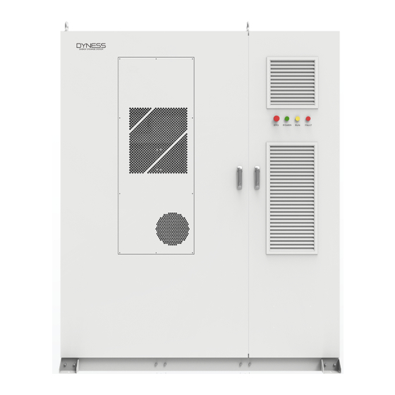
Page 14: Appearance Design
STS module: 1 PV+ESS, no PV, MPPT module: None DH200F-S000L01 On-grid: 100KW, off-grid: 100KW STS module: 1 Appearance design The exterior view of BESS is as follows: Figure 3-3 BESS exterior (front view) ©Dyness reserves the copyright of this document. - Page 15 Constant light indicates a system ● Alarm indicator malfunction Component Size: The BESS is approximately 1846mm long, 1203mm wide (not counting the retainer) and 2250mm high (not counting the lifting ring), the BESS dimensions are as follows: ©Dyness reserves the copyright of this document.
-
Page 16: Internal Design
*The above pictures are for reference only, please refer to the actual object received. Internal design The internal structure and composition of the BESS is shown as below: Figure 3-5 System internal diagram ©Dyness reserves the copyright of this document. - Page 17 EMS Module of the entire system PV disconnect switch Breaks and protects the PV side (optional) Grid Switch Breaks and protects the Grid side Load switch (optional) Breaks and protects the Load side ©Dyness reserves the copyright of this document.
- Page 18 Figure 3-6 BESS secondary switch Table 3-7 Ethernet Port Function Terminal Name Functionality UPS input switch Battery fan power switch System secondary power supply switch Socket switch Air conditioning switch METER Three-phase meter LAN1 Ethernet port ©Dyness reserves the copyright of this document.
-
Page 19: System Parameters
PV access: (Applicable to all models, the "S" followed by a number represents the PV power. For example, S150L00 indicates a 3-channel MPPT with a power of 150 kW.) Input voltage 200-670V Number of MPPT paths ©Dyness reserves the copyright of this document. -
Page 20: Core Modules
The appearance of the battery module is shown below: Figure 3-7 The appearance of battery module ©Dyness reserves the copyright of this document. - Page 21 Please do not touch the electrolyte directly, if skin contact accidentally, please flush with plenty of water. EMS (Energy Management System) is an essential component of energy storage systems. It works in conjunction with PCS, MPPT (optional), STS (optional), BMS, environmental ©Dyness reserves the copyright of this document.
- Page 22 It performs functions such as voltage and current acquisition, circuit contactor control, and protection for battery clusters. The BMS stabilizes and secures the battery function by monitoring the battery status in ©Dyness reserves the copyright of this document.
- Page 23 In the event of an anomaly detected by the water immersion sensor, the system will also stop operating and report the anomaly. The block diagram of the fire protection system is shown below: ©Dyness reserves the copyright of this document.
-
Page 24: Application Scenario
Transformer Meter Power load Grid Charging during low tariff periods Discharging during high tariff periods BESS ©Dyness reserves the copyright of this document. - Page 25 When the load is low, the storage power station gives priority to storing distributed new energy (photovoltaic/wind power) power generation and discharging it at the appropriate time, which reduces the new energy feed-in power, improves the rate of consumption, and maximizes the user's benefit. ©Dyness reserves the copyright of this document.
- Page 26 BESS can stabilize the user voltage and serve as an emergency backup power source, further ensuring the safe and stable operation of the load and minimizing the adverse effects of power quality issues or outages on production and daily life. ©Dyness reserves the copyright of this document.
-
Page 27: Delivery, Transportation And Storage
Select a suitable crane or lifting tool according to the site conditions. The selected tool must have sufficient sufficient load-bearing capacity, arm length, and rotation radius. If movement on slopes or similar conditions is required, additional traction devices may be necessary. ©Dyness reserves the copyright of this document... - Page 28 Under no circumstances should the unit be moved by inserting the pins into a position other than the fork holes √ √ Correct Shipping Method False Shipping Method Figure 4-1 Forklift Transport Diagram ©Dyness reserves the copyright of this document...
-
Page 29: Storage Requirements
To prevent condensation inside the product or soaking of the bottom of the product during the rainy season, the product should be stored on higher ground. The product should be stored on dry, flat, solid ground with sufficient load-bearing ©Dyness reserves the copyright of this document... - Page 30 Starting from the date of delivery, if the storage period for the PACK exceeds six months under the above conditions, perform one charge and discharge cycle to achieve a system SOC of 30% to 40%. After recharging, maintain consistent SOC levels. ©Dyness reserves the copyright of this document...
-
Page 31: Installation
AC side cable trough and the cable guide should be inserted in advance during foundation construction. The specifications and quantity of perforated pipes are based on the cable model and quantity of the cable. ©Dyness reserves the copyright of this document. -
Page 32: Installation Space Requirements
The reserved space in front of a single product should not be less than 1300mm. The reserved space behind a single product should not be less than 800mm. The side view The front view The top view Figure 5-1 Installation Space Requirements ©Dyness reserves the copyright of this document. - Page 33 BESS 2 BESS 3 BESS 4 BESS 5 BESS 6 Combiner Transformer station BESS 10 BESS 12 BESS 7 BESS 8 BESS 9 BESS 11 Figure 5-3 BESS parallel installation space requirements (on-grid scheme) ©Dyness reserves the copyright of this document.
- Page 34 Figure 5-4 BESS parallel installation space requirements (off-grid scheme) 1.Foundation 2.Trench 3.Cable bracket Figure 5-5 Illustration and description of the trench interface 1.Cable bracket 2.Control cable 3.DC cable 4.AC cable Figure 5-6 Schematic and description of cable bracket ©Dyness reserves the copyright of this document. 31 31...
-
Page 35: Wiring
After each step of wiring, it is necessary to check carefully to ensure that the wiring is correct and firm. All electrical connections must be made in strict accordance with the wiring diagram. Wiring Tools Protective items are shown below: ©Dyness reserves the copyright of this document. - Page 36 DH200F User Manual Insulated Gloves Safety Goggles Safety Shoes protective suit Figure 5-7 Safety Gear Phillips Screwdriver Bit Wire stripper Crimping Hair Dryer Multimeter Flat-Head Screwdriver Wrench Drill Tape Measure Figure 5-8 Tools ©Dyness reserves the copyright of this document.
- Page 37 P2+: PV2 positive terminal P2-: PV2 negative terminal P3+: PV3 positive terminal P3-: PV3 negative terminal Figure 5-9 Wiring Area Diagram 1.Copper row 2.Terminal block 3.Bolt 4.Spring pads 5.Flat washers 6.Nut Figure 5-10 Copper End Schematic ©Dyness reserves the copyright of this document.
- Page 38 Be sure to choose flame-retardant cables. The cables used must comply with local laws and regulations. The color of the cables shown in this manual are only suggestions. Please select ©Dyness reserves the copyright of this document.
- Page 39 Slide the heat-shrink tube onto the copper terminal (OT/DT terminal) to fully cover the wire hole. Use a heat gun to tighten the heat-shrink tube. Figure 5-12 The connection sequence of wiring components 1:Heat-shrink tube 2:OT/DT terminal 3:Crimping Pliers 4:Hot air gun ©Dyness reserves the copyright of this document.
- Page 40 LOAD Wiring 2. Bring the cable into the inlet hole and into the electrical cabinet AC (Optional) wiring area. 3. Ensure that the AC cable connections L1, L2, L3 and N are in the ©Dyness reserves the copyright of this document.
- Page 41 Make sure that the sealing strip around the door is not curled after the door is closed! ©Dyness reserves the copyright of this document.
- Page 42 RS485 communication to connect with other devices of customers, these interfaces are non-standard, if necessary, the system will lead the corresponding interface near the front panel for easy wiring. ©Dyness reserves the copyright of this document.
-
Page 43: System Running And Stop
Check to make sure no tools or parts are left inside the device. Operating procedures: The product power-on process is divided into 6 steps: LOAD GRID QF1 QF2 QF3 QF4 ©Dyness reserves the copyright of this document. -
Page 44: Product Power Off Process
After operating step by step, the system will stop running, and the product indicators and screen will go out. After the inspection is completed, wait for five minutes to perform maintenance and inspection operations. ©Dyness reserves the copyright of this document. 41 41... -
Page 45: Human-Machine Interface Of Hmi Screen (Optional)
On the left side of the interface, the sub-menu buttons corresponding to the above six commonly used buttons are displayed, and the selected buttons are marked in yellow. ©Dyness reserves the copyright of this document. -
Page 46: Login Operation Guide
After logging in, the default "Home" is used. Click the [Home] button on the left side of any other interface to enter this interface. In this interface, there are mainly grid three-phase status, STS power, load power, PCS ©Dyness reserves the copyright of this document. - Page 47 Step 6: Enter the control interface. Click the [Control] button to enter the control menu, click the [EMS] button to enter the EMS control interface. By default, it enters the "Period Control" interface, where you can ©Dyness reserves the copyright of this document.
- Page 48 Customers connected to the host computer can also view the system operation data through the host computer. ©Dyness reserves the copyright of this document.
-
Page 49: Fault Description
Stop using it immediately and contact the manufacturer for detector alarm after-sales service Show smoke detector Stop using it immediately and contact the manufacturer for alarm after-sales service Show other alarm Need to contact the manufacturer for after-sales ©Dyness reserves the copyright of this document. -
Page 50: System Maintenance
Check whether the lightning protection device and the fuse are well fastened. Corrosion Check whether there is oxidation or rust inside the outdoor cabinet. System functions Turn on and off to check if the system works abnormally. ©Dyness reserves the copyright of this document. -
Page 51: Quality Assurance
During the warranty period, we require customers to provide valid invoices and dates of purchased products as evidence. At the same time, the Dyness trademark on the product should be clearly visible to ensure the effectiveness of quality assurance. - Page 52 Check whether the HMI screen is displayed normally and no error is reported ☐ Check for lost tools and parts inside the equipment ☐ Check whether the cabinet door is closed and opened flexibly ©Dyness reserves the copyright of this document.
- Page 53 Address: No. 511 Chenzhuang West Road, Sanshui Street, Jiangyan District, Taizhou City Email: service@dyness-tech.com Tel: +86 400 666 0655 Web: www.dyness.com Official Website Digital version access...
Need help?
Do you have a question about the EnerCore DH200F and is the answer not in the manual?
Questions and answers