Advertisement
Introduction

Operating, servicing and maintaining this equipment can expose you to chemicals i ncluding engine exhaust, carbon monoxide, phthalates, and lead, which are known to the State of California to cause cancer and birth defects or other reproductive harm. To minimize exposure, avoid breathing exhaust, do not idle the engine except as necessary, service your equipment in a well-ventilated area and wear gloves or wash your hands frequently when servicing your equipment. For more information go to www.P65Warnings.ca.gov.

This manual contains important instructions for operating this generator. For your safety and the safety of others, be sure to read this manual thoroughly before operating the generator. Failure to properly follow all instructions and precautions can cause you and others to be seriously hurt or killed.
TECHNICAL SPECIFICATIONS
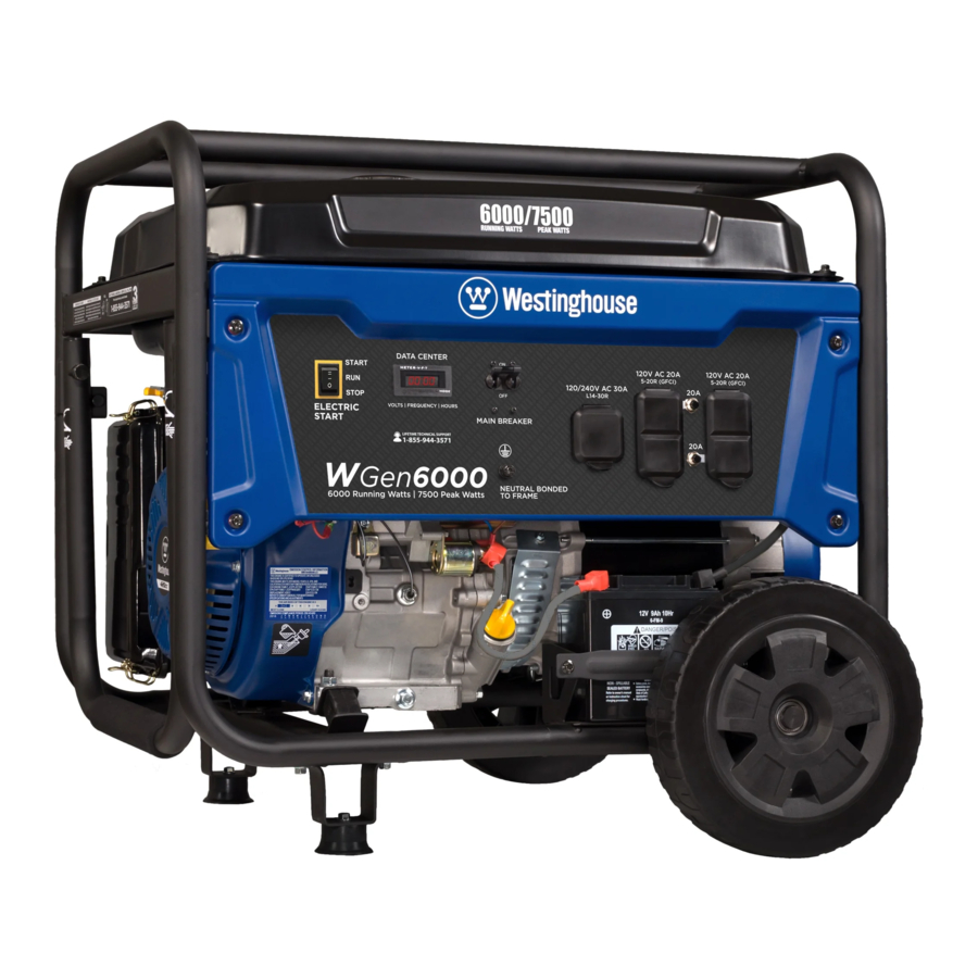
| Model Number | Running Watts | Peak Watts | Fuel Tank Size (L/G) | Rated Speed (RPM) | Ignition Type | Spark plug | Engine Disp (cc) | Stroke X Bore | Oil Capacity (L) | Oil Type | |
| WGen6000 | 6000 | 7500 | 25/6.6 | 3600 | TCI | F7TC | 420 | 66X90 | 1.10 | 10W30 | |
NOTICE
Even with a carburetor modification, engine horsepower will decrease about 3.5% for each 300 meter (1,000 foot) increase in altitude. The effect of altitude on horsepower will be greater if no carburetor modification is made. A decrease in engine horsepower will decrease the power output of the generator. Contact our service team to order altitude kits.
FOR YOUR RECORDS:
Date of Purchase:
Generator Model Number:
Purchased from Store/Dealer:
Generator Serial Number:
HAVE QUESTIONS? Email us at service@wpowereq.com or call 1-855-944-3571

KEEP YOUR PURCHASE RECEIPT TO ENSURE TROUBLE-FREE WARRANTY COVERAGE.
PRODUCT REGISTRATION
To ensure trouble-free warranty coverage, it is important you register your Westinghouse generator.
You can register your generator by either:
- Filling in the product registration form below and mailing to:
Product Registration
MWE Investments LLC
777 Manor Park Drive
Columbus, Ohio 43228 - Registering your product Online at wpowereq.com/register
To register your generator you will need to locate the following information:
WHERE IS MY SERIAL NUMBER?

WESTINGHOUSE PRODUCT REGISTRATION FORM
PERSONAL INFORMATION
First Name:
Last Name:
Street Address:
Street Address:
City, State, ZIP:
Country:
Phone Number:
E-Mail:
GENERATOR INFORMATION
Model Number:
Serial Number:
Date Purchased:
Purchased From:
SAFETY
SAFETY DEFINITIONS
The words DANGER, WARNING, CAUTION and NOTICE are used throughout this manual to highlight important information. Be certain that the meanings of these alerts are known to all who work on or near the equipment.
 This safety alert symbol appears with most safety statements. It means attention, become alert, your safety is involved! Please read and abide by the message that follows the safety alerts symbol.
Indicates a hazardous situation which, if not avoided, will result in death or serious injury.
Indicates a hazardous situation which, if not avoided, could result in death or serious injury.

Indicates a hazardous situation which, if not avoided, could result in minor or moderate injury.
NOTICE
Indicates a situation which can cause damage to the generator, personal property and/or the environment, or cause the equipment to operate improperly.
NOTE: Indicates a procedure, practice or condition that should be followed in order for the generator to function in the manner intended.
SAFETY SYMBOL DEFINITIONS
| Symbol | Description |
 | Safety Alert Symbol |
 | Asphyxiation Hazard |
 | Burn Hazard |
 | Burst/Pressure Hazard |
 | Don't leave tools in the area |
 | Electrical Shock Hazard |
 | Explosion Hazard |
 | Fire Hazard |
 | Lifting Hazard |
 | Pinch-Point Hazard |
 | Read Manufacturer's Instructions |
 | Read Safety Messages Before Proceeding |
 | Wear Personal Protective Equipment (PPE) |
GENERAL SAFETY RULES
Never use the generator in a location that is wet or damp. Never expose the generator to rain, snow, water spray or standing water while in use. Protect the generator from all hazardous weather conditions. Moisture or ice can cause a short circuit or other malfunction in the electrical circuit.
 Never operate the generator in an enclosed area. Engine exhaust contains carbon monoxide. Only operate the generator outside and away from windows, doors and vents.

Voltage produced by the generator could result in death or serious injury.
- Never operate the generator in rain or a flood plain unless proper precautions are taken to avoid being subject to rain or a flood.
- Never use worn or damaged extension cords.
- Always have a licensed electrician connect the generator to the utility circuit.
- Never touch an operating generator if the generator is wet or if you have wet hands.
- Never operate the generator in highly conductive areas such as around metal decking or steel works.
- Always use grounded extension cords. Always use three-wire or double-insulated power tools.
- Never touch live terminals or bare wires while the generator is operating.
- Be sure the generator is properly grounded before operating.
Gasoline and gasoline vapors are extremely flammable and explosive under certain conditions.

- Always refuel the generator outdoors, in a well-ventilated area.
- Never remove the fuel cap with the engine running.
- Never refuel the generator while the engine is running. Always turn engine off and allow the generator to cool before refueling.
- Only fill fuel tank with gasoline.
- Keep sparks, open flames or other form of ignition (such as match, cigarette, static electric source) away when refueling.
- Never overfill the fuel tank. Leave room for fuel to expand. Overfilling the fuel tank can result in a sudden overflow of gasoline and result in spilled gasoline coming in contact with HOT surfaces. Spilled fuel can ignite. If fuel is spilled on the generator, wipe up any spills immediately. Dispose of rag properly. Allow area of spilled fuel to dry before operating the generator.
- Wear eye protection while refueling.
- Never use gasoline as a cleaning agent.
- Store any containers containing gasoline in a well-ventilated area, away from any combustibles or source of ignition.
- Check for fuel leaks after refueling. Never operate the engine if a fuel leak is discovered.
Never operate the generator if powered items overheat, electrical output drops, there is sparking, flames or smoke coming from the generator, or if the receptacles are damaged.
Never use the generator to power medical support equipment.
 Always remove any tools or other service equipment used during maintenance from the generator before operating.
NOTICE
Never modify the generator. Never operate the generator if it vibrates at high levels, if engine speed changes greatly or if the engine misfires often.
Always disconnect tools or appliances from the generator before starting.
SAFETY LABELS AND DECALS


UNPACKING
 Always have assistance when lifting the generator. The generator is heavy; lifting it could cause bodily harm.
Avoid cutting on or near staples to prevent personal injury.
Tools required – box cutter or similar device.
- Carefully cut the packing tape on top of the carton.
- Fold back top flaps to reveal the manual.
- Remove the Wheel Kit Accessories cardboard box.
- Carefully cut two sides of the carton to remove the generator.
WHAT COMES IN THE BOX
Manual Quick Start Guide/Maintenance Schedule 1.1 Liter Bottle of SAE 10W30 Oil (1) Spark Plug Socket Wrench (1) Wheel Kit Accessories Box Funnel (1)
WHEEL KIT ACCESSORIES BOX
Open the Wheel Kit Accessories box and verify the contents against the list right. If any parts are missing, please locate an authorized Westinghouse Generator dealer at service@wpowereq.com or call 1-855-944-3571.


- Washer (2 used)
- Flange Bolt M8 x16mm (4 used)
- Hairpin Cotter Pin (2 used)
- Wheel Axle Pin (2)
ASSEMBLY
INSTALLING WHEELS AND FEET

BEFORE ASSEMBLING THE GENERATOR, REVIEW THE SAFETY SECTION.
 Never lift the generator without assistance. The generator is heavy and lifting without assistance could result in personal injury.
Never use the handles as a lifting point to support the entire weight of the generator. Only use the handles to move the generator by lifting the handles and using the wheels to move the generator.
 Use caution when collapsing the handles. Hands and fingers could get caught and pinched.
NOTICE
Assembling the generator will require lifting the unit on one side. Make sure all engine oil and fuel are drained from the unit prior to assembling. Once assembled, the wheel kit is not intended for on-road use. The wheel kit is designed for use on this generator only.
INSTALLING FEET TO FRAME
- Place generator on a flat surface.
- Place a piece of cardboard or other soft material to tip the generator onto, to protect the frame paint and prevent the generator from sliding. Tip the generator onto the side.
- Install the mounting feet to the frame using the M8 flange bolts included.

- Mounting Foot
- Flange Bolts M8

INSTALLING WHEELS TO FRAME
- Insert axle pin through washer and wheel.

Figure 2 -Wheel Assembly - Install the wheel with axle pin through the axle bracket on the frame. The eye of the bolt should be facing toward the inside of the generator.

Figure 3 - Assemble Wheel to Frame - Install the hairpin cotter through the axle pin to lock it in place.
- Axle Bracket
- Hairpin Clip
- Axle Pin
- Repeat previous steps on other wheel.


CONNECTING THE BATTERY
To avoid electrics shock:
- ALWAYS connect the positive (+) battery cable (red boot) first when connecting battery cables.
- ALWAYS disconnect the negative (-) battery cable (black boot) first when disconnecting battery cables.
- NEVER connect the negative (-) battery cable (black boot) to the positive (+) post on the battery.
- NEVER connect the positive (+) battery cable (red boot) to the negative (-) post on the battery.
- NEVER touch both battery posts simultaneously.
- NEVER place a metal tool across both battery posts.
- ALWAYS use insulated or nonconducting tools when installing the battery.
- Using a screw driver, remove the screw on the red positive (+) battery lead.

- Securely tighten the positive (+) battery cable (red boot) to the positive (+) battery post. Make sure boot is over battery post.

- Locate the black negative (-) cable attached to the alternator case, route it to the negative (-) battery post. See Figure 5 below for location (1) of negative (-) cable.

Figure 5 - Locating Negative (-) Cable - Remove the screw on the negative (-) battery post. Pull back the black boot and securely attach the negative (-) battery cable (black boot) to the negative (-) battery post and tighten screw. Replace the black boot so it protects the cable lug and battery post.


NOTICE
The electric start generator is equipped with a battery charging feature. Once the engine is running, a small charge is supplied to the battery via the battery cables and will slowly recharge the battery.
FEATURES

- Electric Start Switch: Hold in Start position for 1 second to start engine. Make sure to manually open choke prior to cold starting.
- Fuel Cap: Close until clicking sound is heard.
- Control Panel: Contains the circuit breakers and outlets.
- Oil Fill Plug/Dipstick: Must be removed to add and check oil.
- Oil Drain Plug: Must be removed to drain engine oil
- Never Flat Wheels: For easy portability
- Fuel Shut off Valve: Controls the flow of fuel to the engine.
- Manual Choke: Choke must be set manually by adjusting choke lever. Move to ON position for cold starting.
- Single Piece Handle: Includes rubber grip. Allows you to easily push or pull unit with one hand.

- Fuel Gauge: Indicates fuel level.
- Spark Plug Boot (Wire): Must be removed when servicing the engine or the spark plug.
- CARB Canister: Required for models sold into and used in California.
- Muffler and Spark Arrester: Avoid contact until engine is cooled down. Spark arrestor prevents sparks from exiting the muffler. It must be removed for servicing.
- Alternator Cover: Gain access to alternator wiring.
CONTROL PANEL FEATURES

- Electric Start Switch: Hold in START position until engine starts. Make sure to set choke prior to cold starting.
- Data Center: The VFT Meter is 4 state LED display that will rotate through volts, frequency, and lifetime run hours. The 4th display is not used and will always display 00:00. You can press the MODE button to cycle through the different displays. The meter will display volts and hertz even if there is no load connected.
The frequency and voltage can vary +/- 5% and still be within tolerance.![]()
Voltage ![]()
Frequency in hertz ![]()
Lifetime run hours ![]()
Inoperative - Main Circuit Breaker: The main circuit breaker controls total output of all outlets to protect the generator.
- 120/240-Volt, 30-Amp Twist Lock Outlet (NEMA L14-30R): Outlet can supply either 120V or 240V output.
- 120-Volt, 20-Amp Duplex GFCI Outlets (NEMA 5-20R): Each outlet is capable of carrying a maximum of 20 amps on a single receptacle or a combination of both receptacles.
- 20-Amp Circuit Breakers: Each circuit breaker limits the current that can be delivered through the 120-volt duplex outlets to 20amps.
- Ground Terminal: The ground terminal is used to ground the generator.


OPERATION
BEFORE STARTING THE GENERATOR

BEFORE STARTING THE GENERATOR, REVIEW SAFETY SECTION.
Location Selection – Before starting the generator, avoid exhaust and location hazards by verifying:
- You have selected a location to operate the generator that is outdoors and well ventilated.
- You have selected a location with a level and solid surface on which to place the generator.
- You have selected a location that is at least 15 feet (4.5 m) away from any building, other equipment or combustible material.
- If the generator is located close to a building, make sure it is not located near any windows, doors and/or vents.
Using a generator indoors CAN KILL YOU IN MINUTES. Generator exhaust contains carbon monoxide. This is a poison you cannot see or smell.

Never use inside a home or garage. EVEN IF doors and windows are open.

Only use OUTSIDE and far away from windows, doors, and vents.
Avoid other generator hazards. READ MANUAL BEFORE USE.

Always operate the generator on a level surface. Placing the generator on non level surfaces can cause the generator to tip over, causing fuel and oil to spill. Spilled fuel can ignite if it comes in contact with an ignition source such as a very hot surface.
NOTICE
Only operate the generator on a solid, level surface. Operating the generator on a surface with loose material such as sand or grass clippings can cause debris to be ingested by the generator that could:
- Block cooling vents
- Block air intake system
Weather – Never operate your generator outdoors during rain, snow or any combination of weather conditions that could lead to moisture collecting on, in or around the generator.
Dry Surface – Always operate the generator on a dry surface free of any moisture.
No Connected Loads – Make sure the generator has no connected loads before starting it. To ensure there are no connected loads, unplug any electrical extension cords that are plugged into the control panel receptacles.
NOTICE
Starting the generator with loads already applied to it could result in damage to any appliance being powered off the generator during the brief start-up period.
Grounding the Generator – The National Electric Code (NEC), as well as many local electrical codes, may require the generator to be connected to earth ground. The most common application that requires a ground rod is when you are using the generator as a separately derived system to provide back up power to your house. Typically this is when a transfer switch has a switched neutral.
As the generator application has many variables that cannot be determined by the manufacturer of the generator, a licensed electrician will need to determine if a grounding rod is needed.
If a licensed electrician has determine the application requires a ground rod, make sure it is connected to earth ground by connecting the ground terminal on the control panel to earth ground using copper wire (minimum 10 AWG). Consult a qualified electrician for local grounding requirements.
Neutral Bonded: There is a permanent conduct or between the generator (stator winding) and the frame.
Be sure the generator is properly connected to earth ground before operating. The generator must be grounded to prevent electrical shock due to faulty appliances.
High Altitude Operation
Engine power is reduced the higher you operate above sea level. Output will be reduced approximately 3.5% for every 1000ft of increased altitude from sea level. This is a natural occurrence and cannot be adjusted by engine. Increased exhaust emissions can also result due to increased fuel mixture. Other issues include hard starting, increased fuel consumption and spark plug fouling. Contact our service team 1-855-944-3571 for altitude part kits. High Altitude Carburetor Kit Part Number: 140545
POWERCORD
Using Extension Cords
Westinghouse Portable Power assumes no responsibility for the content within this table. The use of this table is the responsibility of the user only. This table is intended for reference only. The results produced by using this table are not guaranteed to be correct or applicable in all situations as the type and construction of cords are highly variable. Always check with local regulations and a licensed electrician prior to installing or connecting an electrical appliance

Using Westinghouse Power Cord
Use the extension cord chart to determine the size of the conductor for extension cord applications. Determine the distance of the generator to the appliance on the top line of the chart. Then select the rated amperage of the generator on the left side of the chart. Where the two meet is the size of the conductor required for the application.
The WCG25 power cord is connected to the generator at the 120/240 plug. The opposite end of the power cord is a fan tail receptacle with 2 green receptacles and 2 red receptacles. Each receptacle is rated at 120 volts AC. To balance the load on the generator's alternator, use the red and green identifiers on the fan tail receptacle. To keep the load balanced, connect the loads so that both color receptacles are used. An example is one in red and one in green. Do not connect 2 in red and none in green, or 2 in green and none in red. If only one color receptacle is used with multiple loads, the alternator may experience an unbalanced load, causing undue vibration to generator.

CONNECTING THE GENERATOR TO A BUILDING ELECTRICAL SYSTEM
It is recommended to use a manual transfer switch when connecting directly to a buildings electrical system. Connecting a portable generator to a buildings electrical system must be made in strict compliance with all national and local electrical codes and laws, and be completed by a qualified electrician.
TRANSFER SWITCH CONNECTIONS
The Westinghouse generator is wired with the neutral bonded to ground. If you are connecting your generator to a panel board transfer switch, a licensed electrician will need to consider removing the bonded neutral to ensure proper operation of household GFCI circuits. Begin by removing the alternator cover (14). Once the cover is off remove the nut that holds the bonded ground jumper wire (see "2" in Figure 6). Once the nut is removed take the bonded jumper wire off and resecure the nut. Next remove the screw holding the neutral ground wire (see "1" in Figure 6). Attach the bonded jumper wire (2) to the neutral ground (1) and tighten the screw.
If the bonded neutral is removed the generator must be relabeled as floating neutral on the control panel.
If your generator is equipped with GFCI receptacles, removing the bonded neutral may not allow proper operation of the GFCI receptacles. Always keep the jumper wire in case it is needed for future use when not connected to a transfer switch.

ADDING / CHECKING ENGINE FLUIDS AND FUEL

BEFORE ADDING/CHECKING ENGINE FLUIDS AND FUEL, REVIEW SAFETY SECTION.

Filling the fuel tank with gasoline while the generator is running can cause gasoline to leak and come in contact with hot surfaces that can ignite the gasoline.
Before starting the generator, always check the level of:
- Engine oil
- Gasoline in the fuel tank
Once the generator is started and the engine gets warm, it is not safe to add gasoline to the fuel tank or engine oil to the engine while the engine is running or the engine and muffler are hot.
CHECKING AND / OR ADDING ENGINE OIL

Internal pressure can build in the engine crankcase while the engine is running. Removing the oil fill plug/ dipstick while the engine is hot can cause extremely hot oil to spray out of the crankcase and can severely burn skin. Allow engine oil to cool for several minutes before removing the oil fill plug/dipstick.
The unit as shipped does not contain oil in the engine. You must add engine oil before starting the generator for the first time. See Checking Engine Oil and Adding Engine Oil for instructions on checking engine oil level and the procedure for adding engine oil.
NOTICE
The engine does not contain engine oil as shipped. Attempting to start the engine can damage engine components. The owner of the generator is responsible to ensure the proper oil level is maintained during the operation of the generator. Failure to maintain the proper oil level can result in engine damage.
ADDING GASOLINE TO THE FUEL TANK
 Never refuel the generator while the engine is running.
 Always turn the engine off and allow the generator to cool before refueling.
Required Gasoline – Only use gasoline that meets the following requirements:
- Unleaded gasoline only
- Gasoline with maximum 10% ethanol added
- Gasoline with an 87 octane rating or higher
Filling the Fuel Tank – Follow the steps below to fill the fuel tank:
- Shut off the generator.
- Allow the generator to cool down so all surface areas of the muffler and engine are cool to the touch.
- Move the generator to a flat surface.
- Clean area around the fuel cap.
- Remove the fuel cap by rotating counterclockwise.
- Slowly add gasoline into the fuel tank. Be very careful not to overfill the tank. The gasoline level should NOT be higher than the filler neck (see Figure 7).

- Install the fuel cap by rotating clockwise until you hear a click, indicating the cap is completely installed.

Avoid prolonged skin contact with gasoline. Avoid prolonged breathing of gasoline vapors.
BEFORE STARTING THE GENERATOR

BEFORE STARTING THE GENERATOR, REVIEW SAFETY SECTION.
Before attempting to start the generator, verify the following:
- The engine is filled with engine oil. SeeChecking Engine Oil.
- The generator is situated in a proper location (Location Selection).
- The generator is on a dry surface (Weather and Dry Surface).
- All loads are disconnected from the generator (No Connected Loads).
- The generator is properly grounded.

Never use the generator in a location that is wet or damp. Never expose the generator to rain, snow, water spray or standing water while in use. Protect the generator from all hazardous weather conditions. Moisture or ice can cause a short circuit or other malfunction in the electrical circuit.

Never operate the generator in an enclosed area. Engine exhaust contains carbon monoxide. Only operate the generator outside and away from windows, doors and vents.
NOTICE
The engine is equipped with a low oil shutdown switch. If the oil level becomes low, the engine may shut down and not start until the oil is filled to the proper level. Poor oil quality may interfere with the operation of the low oil shutdown switch.
The owner of the generator is responsible to ensure the proper oil level is maintained during the operation of the generator. Failure to maintain the proper oil level can result in engine damage.
NOTICE
DO NOT connect 240V loads to a 120V receptacles. DO NOT connect 3-phase loads to the generator. DO NOT connect 50Hz loads to the generator. Let engine stabilize and warm up for a few minutes before adding load.
POWER OUTPUT AND DEMAND
The generator should not be run completely unloaded for extended periods otherwise the engine may be damaged. It is recommended that the generator should always be operated with at least one-third of its rated 120-Volt AC power output. 120-Volt AC devices have two different electric power demands that must be taken into consideration, namely the running power and the starting/peak power. Both are measured in Watts (typically abbreviated as "W").
The steady state continuous load is the running power demand and this is often marked on the device near its model number or serial number. Sometimes the device might only be marked with its voltage (i.e. 120 V) and current draw (e.g. 6 Amp or 6 A), in which case the running power demand in Watts can be obtained by multiplying the voltage times the current, e.g. 120 V × 20 A = 2,400 W.
Simple resistive 120-Volt AC devices such as incandescent bulbs, toasters, heaters, etc. have no extra power demand when starting, and so their starting power demands are the same as their running power demands.
More complex 120-Volt AC devices containing inductive or capacitive elements such as electric motors have a momentary extra power demand when starting, which can be up to seven times the running power demand or more. Manufacturers of such devices rarely publish this starting power demand and so it's often necessary to estimate it. A rule of thumb for devices fitted with an electric motor is to apply a starting power multiplier of 1.2 for small hand-held or portable devices and a value of 3.5 for larger stationary devices. For example, a 900 W angle grinder can be assumed to have a starting power demand of at least 1.2 × 900 W, which equals 1,080 W. Similarly, a 1,650 W air compressor can be assumed to have a starting power demand of at least 3.5 × 1,650 W, which equals 5,775 W.
To prevent overloading of the generator's 120-Volt AC system:
- Add up the running power demand of all the 120-Volt AC devices that will be connected to the generator at one time. This total must not be greater than the generator's specified running power output.
- Add up the running power demand again, but for the largest motor-driven device use the value of its starting power demand instead of its running power demand. This total must not be greater than the generator's specified starting power output.
- The total running power demand of all the devices that will be connected to any one of the generator's outlets must not exceed the generator's specified running power output or 3,700 W, whichever is the lesser.
STARTING THE GENERATOR
Be sure to check oil levels before starting. If it is the first time starting make sure to add oil (see Adding Engine Oil).
- Make sure nothing is plugged into power outlets.
- Verify the battery is installed and both battery cables are attached to their corresponding polarity.
(See Installing the Battery) - Make sure the circuit breakers are properly set (see Figure 8 below).

- 240/120VMain Circuit Breaker Operating Position
- 240/120V Main Circuit Breaker Tripped Position
- 120V Circuit Breaker Operating Position
- 120V Circuit Breaker Tripped Position
- Move the fuel shut off valve to theON position (see Figure 9 below).
![]()
- For cold starting move the choke lever to theON position (see Figure 10 below). If warm starting move choke to OFF position.

- Choose starting method:
- Electric Start: Push and hold the engine control switch in the START position until the engine starts. Once the engine starts, release the engine control switch; the switch will automatically move into the RUN position (see Figure 11 below).

NOTICE
Failure to release the engine control switch once the engine starts could result in damage to the generator. Never push the engine control switch to the START position while the engine is running' this could damage the generator.
Note: If the engine fails to start after 5 seconds, release the engine control switch. Let the generator sit idle for 15 seconds and then repeat step 8. If the cranking speed drops after each unsuccessful attempt, then the battery may not be adequately charged. Manually start the generator by following steps below: - Manual Start: Make sure the engine control switch is in the RUN position. Firmly grasp and pull the recoil handle slowly until you feel increased resistance. At this point, apply a rapid pull while pulling up and slightly away from the generator.

- Electric Start: Push and hold the engine control switch in the START position until the engine starts. Once the engine starts, release the engine control switch; the switch will automatically move into the RUN position (see Figure 11 below).
- After cold starting, as the engine starts and stabilizes, gradually move the choke lever back to theOFF position (see Figure 13 below).

- Plug in electric devices.


STOPPING THE GENERATOR
Normal Operation
During normal operation, use the following steps to stop your generator:

- Remove any connected loads from the control panel receptacles.
- Allow the generator to run at "no load" to reduce and stabilize engine and alternator temperatures.
- Position the engine control switch toSTOP or if you plan to store the generator after use, turn the fuel shutoff valve to the OFF position and allow the fuel to be consumed from the carburetor (see Figure 14).
During an Emergency
If there is an emergency and the generator must be stopped quickly, position the engine control switch to the STOP position immediately.
MAINTENANCE

BEFORE PERFORMING MAINTENANCE ON THE GENERATOR, REVIEW THE SAFETY SECTION, AS WELL AS THE FOLLOWING SAFETY MESSAGES.
Avoid accidentally starting the generator during maintenance by removing the spark plug boot from the spark plug. For electric start generators, also disconnect the battery cables from the battery (disconnect the black negative (-) cable first) and place the cables away from the battery posts to avoid arcing.

Allow hot components to cool to the touch prior to performing any maintenance procedure.

Internal pressure can build in the engine crankcase while the engine is running. Removing the oil fill plug/ dipstick while the engine is hot can cause extremely hot oil to spray out of the crankcase and can severely burn skin. Allow engine oil to cool for several minutes before removing the oil fill plug/dipstick.

Always perform maintenance in a wellventilated area. Gasoline fuel and fuel vapors are extremely flammable and can ignite under certain conditions.
MAINTENANCE SCHEDULE
Failure to perform periodic maintenance or not following maintenance procedures can cause the generator to malfunction and could result in death or serious injury.
NOTICE
Periodic maintenance intervals vary depending on generator operating conditions. Operating the generator under severe conditions, such as sustained highload, high-temperature, or unusually wet or dusty environments, will require more frequent periodic maintenance. The intervals listed in the maintenance schedule should be treated only as a general guideline.

Avoid skin contact with engine oil or gasoline. Prolonged skin contact with engine oil or gasoline can be harmful. Frequent and prolonged contact with engine oil may cause skin cancer. Take protective measures and wear protective clothing and equipment. Wash all exposed skin with soap and water.
Following the maintenance schedule is important to keep the generator in good operating condition. The following is a summary of maintenance items by periodic maintenance intervals.
TABLE 1: MAINTENANCE SCHEDULE - OWNER PERFORMED
| Maintenance Item | Before Every Use | After First 20 Hours or First Month of Use | After 50 Hours of Use or Every 6 Months | After 100 Hour of Use or Every 6 Months | After 300 Hours of Use or Every Year |
| Engine Oil | Check Level | Change | Change | - | - |
| Cooling Features | Check/Clean | - | - | - | - |
| Air Filter | Check | - | Clean* | - | Replace |
| Spark Plug | - | - | - | Check/Clean | Replace |
| Spark Arrestor | - | - | - | Check/Clean | - |
*Service more frequently if operating in dry and dusty conditions
TABLE 2: MAINTENANCE SCHEDULE - AUTHORIZED WESTINGHOUSE SERVICE DEALER PERFORMED
| Maintenance Item | Before Every Use | After First 20 Hours or First Month of Use | After 50 Hours of Use or Every 6 Months | After 100 Hour of Use or Every 6 Months | After 300 Hours of Use or Every Year |
| Valve Clearance | - | - | - | - | Check/Adjust |
| Fuel Filter | - | - | - | Check/Clean | - |
CLEANING THE SPARK ARRESTOR

Hot Surfaces. When operating machine, do not touch hot surfaces. Keep machine away from combustibles during use. Hot surfaces could result in severe burns or fire.
Check and clean the spark arrestor after every 100 hours of use or 6 months.
- Generator must be cold to perform this maintenance.
- Move the inverter to a flat, level surface.
- Remove the 6 screws holding the muffler cover in place (see Figure 15).

- Once the cover is removed, locate the screw on the tip of the muffler and remove. Pull the spark arrestor out of the muffler. (see Figure 16).

- If the spark arrestor screen shows signs of wear (rips, tears or large openings in the screen), replace the spark arrestor screen.
NOTE: Only use Westinghouse spark arrestors as replacements. - If screen is not torn then clean using a wire brush, commercial solvent, or compressed air. Remove any dirt and debris that may have collected on the spark arrestor screen (see Figure 17).
![]()
- Install the spark arrestor back into the muffler. Make sure to fully push it in so that it is tight on the tip of the muffler.
- Replace the muffler cover and tighten all 6 screws.


DRAINING CARBURETOR FLOAT BOWL

- Make sure the generator is off and you are away from any open flames.
- Place pan (or suitable container) under the carburetor assembly.
- Loosen screw at bottom of the bowl and allow gas to drain out.
- After all the gas has drained out, tighten the screw.
ENGINE OIL MAINTENANCE
Engine Oil Specification
- Only use the engine oil specified in Figure 18.

- Only use 4-stroke/cycle engine oil. NEVER USE 2-STROKE/CYCLE OIL. Synthetic oil is an acceptable substitute for conventional oil.

CHECKING ENGINE OIL
NOTICE
Always maintain proper engine oil level. Failure to maintain proper engine oil level could result in severe damage to the engine and/or shorten the life of the engine. Always use the specified engine oil. Failure to use the specified engine oil can cause accelerated wear and/or shorten the life of the engine.
Engine oil level should be checked before every use.
- Always operate or maintain the generator on a flat surface.
- Stop engine if running.
- Let engine sit and cool for several minutes (allow crankcase pressure to equalize).
- With a damp rag, clean around the oil fill plug/dipstick.
- Remove oil fill plug/dipstick (see Figure 19 below).

- Check oil level: When checking the engine oil, remove the oil fill plug/dipstick and wipe it clean. Thread the oil fill plug/dipstick all the way back in and then remove and check the oil level on the oil fill plug/ dipstick.
- Acceptable Oil Level – Oil is visible on the crosshatches between the H and L lines on the oil fill plug/dipstick (see Figure 20).

- Low Oil – Oil is below the L line on the oil fill plug/ dipstick.
- Acceptable Oil Level – Oil is visible on the crosshatches between the H and L lines on the oil fill plug/dipstick (see Figure 20).


ADDING ENGINE OIL
- Always operate or maintain the generator on a flat surface.
- Stop engine if running.
- Let engine sit and cool for several minutes (allow crankcase pressure to equalize).
- Thoroughly clean around the oil fill plug/dipstick.
- Remove oil fill plug/dipstick and wipe clean.
- Select the proper engine oil as specified in Figure 18.
- Using the supplied funnel, slowly add engine oil to the engine. Stop frequently to check the level to avoid overfilling.
- Continue to add oil until the oil is at the correct level. See Figure 20.
- Replace the oil fill plug/dipstick.
CHANGING ENGINE OIL
- Always operate or maintain the generator on a flat surface.
- Stop the engine.
- Let engine sit and cool for several minutes (allow crankcase pressure to equalize).
- Place oil pan (or suitable container) under the oil drain plug (see Figure 21).

- With a damp rag, thoroughly clean around the oil drain plug.
- Remove the oil drain plug (see Figure 21). Once removed, place the oil drain plug on a clean surface.
- Allow oil to completely drain.
- Replace oil drain plug.
- Fill crankcase with oil following the steps outlined inAdding Engine Oil.

NOTICE
Never dispose of used engine oil by dumping the oil into a sewer, on the ground, or into ground water or waterways. Always be environmentally responsible. Follow the guidelines of the EPA or other governmental agencies for proper disposal of hazardous materials. Consult local authorities or reclamation facility.
AIR FILTER MAINTENANCE

Never use gasoline or other flammable solvents to clean the air filter. Use only household detergent soap to clean the air filter.
Cleaning the Air Filter
The air filter must be cleaned after every 50 hours of use or 3 months (frequency should be increased if generator is operated in a dusty environment).
- Turn off the generator and let it cool for several minutes if running.
- Move the generator to a flat, level surface.
- Unclip the clips on the top and bottom of the air filter cover (Figure 22).

- Remove the black coarse air filters.
- Wash the foam air filter elements by submerging the elements in a solution of household detergent soap and warm water. Slowly squeeze the foam to thoroughly clean.
NOTICE
NEVER twist or tear the foam air filter element during cleaning or drying. Only apply slow but firm squeezing action. - Rinse in clean water by submerging the air filter elements in fresh water and applying a slow squeezing action
NOTICE
Never dispose of soap cleaning solution used to clean the air filter by dumping the solution into a sewer, on the ground, or into ground water or waterways. Always be environmentally responsible. Follow the guidelines of the EPA or other governmental agencies for proper disposal of hazardous materials. Consult local authorities or reclamation facility. - Dispose of used soap cleaning solution properly.
- Dry the air filter elements by again applying a slow firm squeezing action.
- Once the air filters are dry, coat the air filters with clean engine oil.
![]()
- Squeeze the filters to remove any excess oil.
- Install the filters back into the unit. Make sure the gray (fine) air filter goes in first followed by the black (coarse) air filter on the outside.
- Install the air filter cover and secure the air filter assembly.


SPARK PLUG MAINTENANCE
The spark plug must be checked and cleaned after every 100 hours of use or 6 months and must be replaced after 300 hours of use or every year.
- Stop the generator and let it cool for several minutes if running.
- Move the generator to a flat, level surface.
- Remove the spark plug boot by firmly pulling the plastic spark plug boot handle directly away from the engine (see Figure 23).
NOTICE
Never apply any side load or move the spark plug laterally when removing the spark plug. Applying a side load or moving the spark plug laterally may crack and damage the spark plug boot.

- Clean area around the spark plug.
- Using the spark plug socket wrench provided, remove the spark plug from the cylinder head.
- Place a clean rag over the opening created by the removal of the spark plug to make sure no dirt can get into the combustion chamber.
Inspect the spark plug for:- Cracked or chipped insulator
- Excessive wear
- Spark plug gap (the acceptable limit of 0.027–0.032 in. [0.70 – 0.80 mm]).
NOTICE
Use only recommended spark plugs when servicing. The manufacturer is not responsible for engine damage when using spark plugs not recommended by the manufacturer.
![]()
- Install the spark plug by carefully following the steps outlined below:
- Carefully insert the spark plug back into the cylinder head. Hand-thread the spark plug until it bottoms out.
- Using the spark plug socket wrench provided, turn the spark plug to ensure it is fully seated.
- Replace the spark plug boot, making sure the boot fully engages the spark plug's tip.


Recommended Spark Plug Replacement:
NGK: (1034) BP7ES (Replacement)
Torch: F7TC (OE Spark Plug)
Westinghouse Part Number: 180526
CHECKING AND ADJUSTING VALVE LASH
Checking and adjusting valve lash must be done when the engine is cold.
- Remove the rocker arm cover and carefully remove the gasket. If the gasket is torn or damaged, it must be replaced.
- Remove the spark plug so the engine can be rotated more easily.
- Rotate the engine to top dead center (TDC) of the compression stroke. Looking through the spark plug hole, the piston should be at the top.
- Both the rocker arms should be loose at TDC on the compression stroke. If they are not, rotate the engine 360°.
- Insert a feeler gauge between the rocker arm and the push rod and check for clearance (see Figure 24). See Table 3 for valve lash specifications.


(Table 3) Standard Valve Lash
| Intake Valve | Exhaust Valve | |
| Valve Lash | 0.0035 ± 0.0043 in (0.09 ± 0.11 mm) | 0.0043 ± 0.0051 in (0.11 ± 0.13 mm) |
| Bolt Torque | 8-12N.m | 8-12N.m |
- If an adjustment is required, hold the adjusting nut and loosen the jam nut.
- Turn the adjusting nut to obtain the correct valve lash. When the valve lash is correct, hold the adjusting nut and tighten the jam nut to 106 in-lb (12 N•m).
- Recheck the valve lash after tightening the jam nut.
- Perform this procedure for both the intake and exhaust valves.
- Install the rocker arm cover, gasket and spark plug.
TESTING GFCI OUTLETS
- Start the generator and allow it to warm up.
- Press the test button on the GFCI outlet.

- The reset button should pop out and there will be no power from the outlets. If the reset button does not pop out, the GFCI outlet is not working correctly and must be repaired before the generator can be operated.
- Press the reset button to restore power to the outlet.

BATTERY SERVICE
Do not charge for over 8 hours. Leaving the battery on the charger indefinitely could overcharge the battery and lead to battery failure
To ensure the battery remains charged, the generator should be started every 2 to 3 months and run for a minimum of 15 minutes or a charger should be connected to the battery and charged overnight. If using a battery charger be sure to follow instructions provided by the manufacturer for proper use.
BATTERY REPLACEMENT
- Remove the spark plug wire from spark plug.
- Loosen and remove the bolt on the battery hold down plate and swing the plate out.
- Tip the battery forward slightly to access battery cables.
- Disconnect the black negative (-) battery cable from the battery first.
- Disconnect the red positive (+) battery cable second and remove the battery.
NOTICE
Dispose of the used battery properly according to the guidelines established by your local or state government. - Install the new battery into the generator frame. Battery must meet specifications in table below to work properly.
- Connect the red positive (+) battery cable to the battery first.
- Connect the black negative (-) battery cable to the battery second.
- Install the battery hold-down plate using the nuts removed in step 2.
- Install the spark plug wire onto spark plug.
See below for the battery specification when replacing the battery.
| Westinghouse Part No. | 100557 |
| After Market Battery Model | YT9A |
| Volts | 12 |
| Amp Hr | 9 |
| Dimensions | 5 5/16in by 3in by 5 3/8in |
CLEANING THE GENERATOR
It is important to inspect and clean the generator after every use.
Clean All Engine Air Inlet and Outlet Ports – Make sure all engine air inlet and outlet ports are clean of any dirt and debris to ensure the engine does not run hot.
Clean All Engine Cooling Fins – Use a damp rag and a brush to loosen and remove all dirt on or around the engine's cooling fins.
Clean All Alternator Cooling Air Inlets and Exhaust Ports – Make sure the cooling air inlets and exhaust ports of the alternator are free of any debris and obstructions. Use a vacuum cleaner to remove dirt and debris stuck in the cooling air inlets and exhaust ports. General Cleaning of the Generator – Use a damp rag to clean all remaining surfaces.
STORING GENERATOR

Never store a generator with fuel in the tank indoors or in a poorly ventilated area where the fumes can come in contact with an ignition source such as a:
- pilot light of a stove, water heater, clothes dryer or any other gas appliance; or
- spark from an electric appliance.
NOTICE
Gasoline stored for as little as 60 days can go bad, causing gum, varnish and corrosive buildup in fuel lines, fuel passages and the engine. This corrosive buildup restricts the flow of fuel, preventing an engine from starting after a prolonged storage period.
Proper care should be taken to prepare the generator for any storage.
- Make sure the Engine Switch is switched toSTOP so the generator does not draw power from battery.
- Clean the generator as outlined inCleaning the Generator.
- Drain all gasoline from the fuel tank as best as possible.
- With the fuel shut off valve open, start the engine and allow the generator to run until all the remaining gasoline in the fuel lines and carburetor is consumed and the engine shuts off.
- Close the fuel shut off valve.
- Drain the remaining gas in the carburetor float bowl outlined inDraining Carburetor Float Bowl.
- Change the oil (seeChanging Engine Oil).
- Remove the spark plug (seeSpark Plug Maintenance) and place about 1 tablespoon of oil in the spark plug opening. While placing a clean rag over the spark plug opening, slowly pull there coil handle to allow the engine to turn over several times. This will distribute the oil and protect the cylinder wall from corroding during storage.
- Replace the spark plug (seeSpark Plug Maintenance).
- Move the generator to a clean, dry place for storage.
TROUBLESHOOTING

Before attempting to service or troubleshoot the generator, the owner or service technician must first read the owner's manual and understand and follow all safety instructions. Failure to follow all instructions may result in conditions that can lead to voiding of the EPA certification or product warranty, serious personal injury, property damage or even death.
| PROBLEM | POTENTIAL CAUSE | SOLUTION |
Engine is running, but no electrical output |
|
|
|
| |
|
| |
|
| |
|
| |
|
| |
| Engine will not start or remain running while trying to start. |
|
|
|
| |
|
| |
|
| |
|
| |
|
| |
|
| |
|
| |
|
| |
|
| |
|
| |
|
| |
Generator suddenly stops running |
|
|
|
| |
|
| |
|
| |
Engine runs erratic; does not hold a steady RPM |
|
|
|
| |
|
| |
|
|
WGEN6000 EXPLODED VIEW

WGEN6000 EXPLODED VIEW PART NO.


WGEN6000 ENGINE VIEW

WGEN6000 ENGINE VIEW PART NO.


WGEN6000 SCHEMATIC

Generator Specifications

Documents / Resources
References

Download manual
Here you can download full pdf version of manual, it may contain additional safety instructions, warranty information, FCC rules, etc.
Advertisement


Need help?
Do you have a question about the WGen6000 and is the answer not in the manual?
Questions and answers