Table of Contents

Related Manuals for Optec UMG 96-PA


Summary of Contents for Optec UMG 96-PA
- Page 1 Power Analyzer UMG 96-PA (Firmware 2.0 and higher) User Manual and Technical Data Janitza electronics GmbH Vor dem Polstück 6 35633 Lahnau, Germany Support tel. +49 6441 9642-22 Fax +49 6441 9642-30 E-mail: info@janitza.com www.janitza.com...
- Page 2 UMG 96-PA www.janitza.com UMG 96-PA (Firmware 2.0 and higher) Measurement device for recording energy measured values Doc. no.: 2.061.039.0b Status: 04/2019 The German version is the original version of the documentation...
- Page 3 UMG 96-PA Subject to technical changes. The content of our documentation has been compiled with the utmost care and is based on the latest information available to us. Nevertheless, we would like to point out that the updating of this document cannot always be performed simultaneously with the further technical development of our products.
-
Page 4: Table Of Contents
UMG 96-PA www.janitza.com TABLE OF CONTENTS 1. Notes on the device and user manual 1. 1 Disclaimer 1. 2 Copyright notice 1. 3 Technical changes 1. 4 About this user manual 1. 5 Defective device/disposal 2. Safety 2. 1 Presentation of warning notices and safety instructions 2. - Page 5 UMG 96-PA 7. Installation 7. 1 Rated voltages 7. 1. 1 Three-phase 4-conductor network with grounded neutral conductor 7. 2 Disconnectors 7. 3 Supply voltage 7. 4 Voltage measurement 7. 4. 1 Overvoltage 7. 4. 2 Frequency 7. 4. 3 Voltage measurement connection versions 7.
- Page 6 UMG 96-PA www.janitza.com 12. Configuration 12. 1 The Configuration window 12. 2 Language 12. 3 Communication 12. 4 Measurement 12. 4. 1 Rated current 12. 4. 2 Rated frequency 12. 4. 3 Current transformer and voltage transformer 12. 5 Display 12.
- Page 7 UMG 96-PA 13. 13 Digital inputs and outputs 13. 13. 1 Digital inputs 13. 13. 2 Digital outputs 13. 14 Analog output configuration 13. 15 “Drag pointer” function 13. 15. 1 Internal synchronization 13. 15. 2 External synchronization 13. 15. 3 Synchronization priority 13.
-
Page 8: Notes On The Device And User Manual
1.3 Technical changes · Make sure that the user manual matches your device. · This user manual is valid for the UMG 96-PA (Firmware 2.0 and higher). · First, make sure you have read and understood the document accompanying the product. -
Page 9: Defective Device/Disposal
UMG 96-PA 1.5 Defective device/disposal Please contact the manufacturer's support department before sending defective devices (components) back to the manufacturer for testing (complete with accessories). Take the transport conditions into consideration. NOTE Please return defective or damaged devices to Janitza electronics GmbH. Observe the shipping instructions for air freight and road (complete with accessories). -
Page 10: Safety
UMG 96-PA www.janitza.com Safety 2.2 Danger levels Please read the present user manual and all other publications that are applicable for working Warning notices and safety instructions are with this product. This applies in particular for highlighted by a warning symbol and the danger installation, operation and maintenance. -
Page 11: Safety Measures
UMG 96-PA 2.3 Safety measures 2.4 Qualified personnel When operating electrical devices, specific parts To prevent personal injuries and property of these devices inevitably carry dangerous damage, only electrically qualified personnel voltage. As a result, serious bodily harm or... -
Page 12: Product Description
UMG 96-PA www.janitza.com Product description 3.1 Incoming goods inspection 3.3 Intended use The prerequisites for smooth and safe The device is: operation of this device and its components · intended for installation in switching cabinets include proper transport, storage, setup and and small installation distributors. -
Page 13: Scope Of Delivery
UMG 96-PA 3.5 Scope of delivery Number Item no. Designation 52.32.xxx UMG 96-PA 33.03.360 Installation instructions 33.03.342 “Safety instructions” supplement. 33.03.361 Quick start “GridVis” software. 10.01.896 Screw-type terminal, pluggable, 3-pole (auxiliary supply) 10.01.849 Screw-type terminal, pluggable, 4-pole (voltage measurement) 10.01.871... -
Page 14: Device Description
UMG 96-PA www.janitza.com 3.6 Device description 3.7 Measurement method The device is suitable for The device measures · measurements and calculations of electric · seamlessly and calculates all effective values in values, such as voltage, current, power, a 200 ms interval. -
Page 15: Performance Features
UMG 96-PA 3.10 Performance features General information • Integrated front panel unit with the dimensions 96 x 96 mm • Extension through module technology • Connection via pluggable screw-type terminals • Color graphic display 320 x 240 px • Operation via 6 keys •... -
Page 16: Design Of The Device
UMG 96-PA www.janitza.com Design of the device 4.1 Front view - display ii. ront view of the UMG 96-PA Device type Description of the function keys Key 1: Configuration menu, back (ESC) Key 2: Select number, set selection field () Key 3: Lower number by 1, select menu item (), set selection field () -
Page 17: Rear View - Location Of The Connections
UMG 96-PA 4.2 Rear view - location of the connections ii. Rear view of the UMG 96-PA Supply voltage RS485 interface Digital inputs Digital outputs Analog output Module connector Current measurement inputs I1 to I3 Voltage measurement inputs V1 to V3... -
Page 18: Rating Plate
UMG 96-PA UMG 96-PA www.janitza.com 4.3 Rating plate UMG 96-PA UMG 96xxx 10H • 000 1234567 XXXX/XXXX Aux: 90..277V, 50/60Hz 90..250V 4,5VA 300V CAT III Made in Germany • www.janitza.com Pos. Designation Description · AC supply voltage in V · Rated frequency in Hz Operating data ·... -
Page 19: Assembly
Mounting plate Clamping screw Mounting bracket Screwdriver ii. Rear view of the UMG 96-PA mountini position Max. 2 additional turns for mounting the device, if the clamping screws touch the mounting plate... -
Page 20: Network Systems
UMG 96-PA www.janitza.com Network systems Installation Network systems and maximum rated voltages The device is suitable for the voltage measure- according to DIN EN 61010-1/A1: ment in TN and TT systems. The voltage measurement of the device has the Three-phase 4-conductor systems... - Page 21 UMG 96-PA 7.2 Disconnectors Install a suitable disconnector for the supply PE/FE voltage in the building installation in order to de-energize the device from current and voltage. 1) Fuse (UL/IEC-listed) · Install the disconnector near the device in 2) Disconnect device a location that is easily reachable for the user.
- Page 22 UMG 96-PA www.janitza.com Overcurrent protection device for the line For measurements with strongly distorted protection of the supply voltage voltages, the frequency of the fundamental voltage oscillation can no longer be determined Recommendation for the overcurrent protection exactly. This means that for measuring voltages...
- Page 23 UMG 96-PA 7.4.3 Voltage measurement connection versions WARNING ii. Voltaie measurement in the Risk of injury due to electric voltage! three-phase 4-conductor Serious personal injury or death may result system Voltage if the connection conditions for the voltage measurement inputs are not observed.
- Page 24 UMG 96-PA www.janitza.com 7.5 Current measurement WARNING The device: Risk of injury due to electric voltage on · is designed for the connection of current current transformers! transformers with secondary currents of High voltage spikes that are dangerous ../1 A to ../5 A.
- Page 25 UMG 96-PA 7.5.1 Current direction 7.5.4 Current measurement connection versions You can correct the current direction individually for each phase via the existing serial interfaces. ii. Current measurement via the current transformer in In case of an incorrect connection, the current...
- Page 26 604 as a slave devices gateway (master) UMG 96-PA RS485 RS485 2. Using the UMG 96-PA (slave) via a UMG ii. RS485 interface, 3-pole plui contact (master) with gateway functionality (e.g. UMG 512): RS485 bus PC with GridVis ® 120 Ω...
- Page 27 UMG 96-PA 8.3 Shielding 8.4 Termination resistors For connections via the interfaces, provide a The cable is terminated with resistors twisted and shielded cable and observe the (120Ω, 1/4 W) at the start and end of a segment. follow points for the shielding: ·...
- Page 28 UMG 96-PA www.janitza.com 8.5 Bus structure In a bus structure be supplied with power. · all devices are connected in line. · placing the master at the end of a segment is · each device has its own address. recommended. If the master is replaced with an ·...
- Page 29 UMG 96-PA...
- Page 30 UMG 96-PA www.janitza.com Digital inputs and outputs The device features External auxiliary voltage 24V DC · 3 digital inputs and · 3 digital outputs. UMG 96-PA 9.1 Digital inputs Digital inputs 1-3 The device features three digital inputs, for connecting one signal transmitter each,...
- Page 31 UMG 96-PA 9.2 Digital outputs The device features 3 digital outputs that · are electrically isolated from the evaluation electronics via optocouplers. · have a common reference. · are not short-circuit proof. ii. Connection of diiital/pulse outputs · require external auxiliary voltage.
- Page 32 UMG 96-PA www.janitza.com 10. Analog output The device features 1 passive analog output, which can output a current of 0 - 20 mA. An external power supply unit (24 V DC) is required for operation. The connectable load must not exceed a resistance of 300 Ohm.
- Page 33 11.2 “Home” measured value indication which are assigned different functions depending UMG 96-PA start screen: on the context: After the power returns, the UMG 96-PA starts with the Home measured value indication. · Selecting displayed measured values. · Navigation within the menus.
- Page 34 UMG 96-PA www.janitza.com 11.4 Overview of menu displays Oscilloscope Menu Voltage L1 Voltage L2 Home(UMG 96-PA start screen) Voltage L3 Voltage L1-3 Voltage Current L1 Voltage L-N Current L2 Voltage L-L Current L3 Curve Current L1-3 Phasor diagram Peripherals Current...
- Page 35 UMG 96-PA Selecting a menu item: · Use keys 3 () and 4 () to select the menu item. · Confirm it using key 6 (Enter). · Use key 1 (Esc) to exit the selection. · Use key 2 (Home) to access the start screen.
- Page 36 UMG 96-PA www.janitza.com 12. Configuration 12.1 The Configuration window 12.2 Language The Confiiuration menu of the device contains In the Laniuaie entry of the Confiiuration all the parameters in which you can make window, you can configure the language for the settings.
- Page 37 UMG 96-PA 12.3 Communication · Baud rate: Select a uniform baud rate for all devices in the In the Communication entry of the Confiiuration bus structure. window, you can configure the parameters for Setting range: Auto, 9600, 19200, 38400, the RS485 interface of your device.
- Page 38 UMG 96-PA www.janitza.com 12.4.1 Rated frequency To determine the power frequency, the device requires a voltage > 20 V (4-conductor The device requires the power frequency for measurement) or a voltage L1-L2 > 34 V measuring and calculating measured values.
- Page 39 UMG 96-PA · In order to return to the Home measured value indication, press key 1 (Esc) 2 times and then key 2 (Home). Rated current settings: Setting range: 0 - 999999 A Default setting: 150 A 12.4.3 Current transformer and voltage...
- Page 40 UMG 96-PA www.janitza.com 12.5 Display · Confirm your entries with key 6 (Enter) or cancel the action with key 1 (Esc). You can configure the following display settings · In order to return to the Home measured value using the Display entry of the measurement...
- Page 41 · 1-99999 = With password · 00000 = No password Default setting: · 00000 = No password The UMG 96-PA is configured ex works with the password 00000 (no password). ii. Confiiuration window with the system entry activated. · The System window appears.
- Page 42 UMG 96-PA www.janitza.com To change the password, you need the current 12.6.4 Reset password. You can use this function to delete and reset measured values and device parameters. NOTE · The measurement device locks the device Energy configuration for 15 minutes after the password is entered incorrectly four times.
- Page 43 UMG 96-PA Minimum and maximum values Factory settings The device user can use this function to This function resets all settings, such as delete all min. and max. values in the device configurations and recorded data, to the factory simultaneously.
- Page 44 UMG 96-PA www.janitza.com Restart Modbus address 30001 This function restarts the measurement device. To configure a start value for your measured value, write the start value to the · Open the Confiiuration window as described Modbus address 30002 above. · Use keys 3 () and 4 () to select the System You enter a final value of your measured entry and confirm with key 6 (Enter).
- Page 45 UMG 96-PA You can access the Modbus editor as follows: Example for the active power measured value: · Open the Confiiuration window as described above. · In the Confiiuration window, select the Modbus · Use keys 3 () and 4 () to select the Modbus editor entry and confirm using key 6 (Enter).
- Page 46 UMG 96-PA www.janitza.com 13. Commissioning 13.1 Connecting the supply voltage WARNING 1. Connect the supply voltage to a terminal on Risk of injury due to electric voltage! the rear of the device. If the device is exposed to surge voltages 2.
- Page 47 UMG 96-PA 13.4 Frequency The device requires the rated frequency or power frequency for measuring and calculating measured values. The power frequency can either be specifi ed by the user or determined automatically by the device. · To determine the power frequency, a voltage...
- Page 48 UMG 96-PA www.janitza.com 13.5.1 Phasor diagram basics Capacity representation: The phasor diagram graphically describes the · The current rushes ahead of the voltage phase shift or phase angle between voltage and · The phase shift of an "ideal capacitor" is 90°.
- Page 49 UMG 96-PA 13.6 Checking the voltage and current inputs 13.7 Exceeding the measurement range using a phasor diagram If the measurement range is exceeded, the The phasor diagram can be used to check “overvoltaie” warning appears in the device incorrect connections at the voltage and current display, e.g.
- Page 50 UMG 96-PA www.janitza.com 13.8 Checking the power measurement 13.9 Checking the communication Short circuit all current transformer outputs The device counts all received (RX), all except for one and check the powers displayed. transmitted (TX) and all faulty data packets.
- Page 51 UMG 96-PA 13.10 Delete min./max. values · To delete the Min./Max. values, press key 6 (Enter). In the measured value indications for voltage, · The Min./Max. values submenu appears. current and power, the device function is deleting · In the Min./Max. values submenu, use keys min./max.
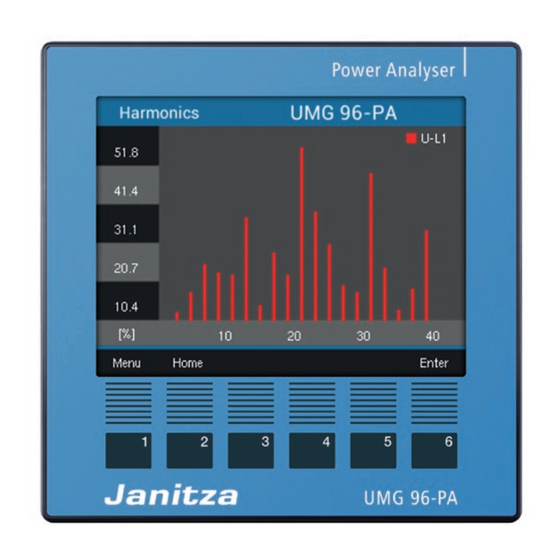
- Page 52 UMG 96-PA www.janitza.com 13.11 Harmonics · The Harmonics of the selected measured value window appears. Harmonics are caused, for example, by equipment with non-linear characteristics. These additional frequencies represent the integer multiple of a power frequency and show how the equipment affects the equipment on the power network.
- Page 53 Parity: (CRC) even none (1 stop bit) The “Response” of the device can then appear none (2 stop bits) as follows: Stop bits (UMG 96-PA): 1 / 2 Designation Hex Remark Stop bits, external: 1 / 2 Device address Address=1...
- Page 54 UMG 96-PA www.janitza.com 13.13 Digital inputs and outputs Your device has three digital outputs and three digital inputs. Digital Outputs Digital Inputs ii. Diiital inputs and outputs · You can confi gure the digital inputs and outputs ii. Confi iuration of the diiital inputs via the GridVis ®...
- Page 55 UMG 96-PA Pulse counters Measurement value calculation: All digital inputs can be operated with a frequency of 25 Hz. The pulse duration Measured value = pulse x pulse value (pulse width) and the pulse pause must be greater than 20 ms.
- Page 56 UMG 96-PA www.janitza.com 13.13.2 Digital outputs Pulse value The pulse value indicates how much energy Different functions can be assigned to the three (Wh or varh) corresponds to a pulse. digital outputs: The pulse value is determined by the maximum ·...
- Page 57 UMG 96-PA 3. Calculating the pulse value: The weekly timers are configured using the GridVis software in the “Timer” configuration ® area) max. connected load [Pulses/Wh] Pulse value = max. number of pulses/h Pulse value = 135 kW / 60000 pulses/h Pulse value = 0.00225 pulses/kWh...
- Page 58 UMG 96-PA www.janitza.com Output for the comparator group Two comparator groups (comparator 1 and 2) with 3 comparators each (A - C) are available for monitoring threshold values. The results of the comparators A to C can be linked “AND” or “OR”.
- Page 59 UMG 96-PA Comparator runtime Comparator runtimes are time counters that add Measured value up when a comparator output is set. This means that if the condition of the comparator is fulfilled Threshold value and the lead time has elapsed, the counter...
- Page 60 UMG 96-PA www.janitza.com 13.14 Analog output configuration Examples: Assiinment of active power L1 The device features an analog output, which can (output ranie 4 - 20 mA) output a maximum current of 20 mA. An external 24 V DC power supply unit is required for operation.
- Page 61 UMG 96-PA 13.15 “Drag pointer” function Capture time: The individually adjustable capture time The "drag pointer" function describes the describes a time slot in which an incoming pulse three highest mean values of value types over synchronizes the time. If the device receives a defined period of time (time base).
- Page 62 UMG 96-PA www.janitza.com 13.15.2 External synchronization “A pulse” If the device receives a pulse or a Modbus An external synchronization for calculating the 3 command once outside the capture time, highest mean values takes place the measured values summed up to that time ·...
- Page 63 UMG 96-PA “Periodic pulses” Scenario "impulse before the time base, but within the capture time": If the device receives periodic pulses via digital input 3 or periodic Modbus commands, there are · Now calculate the value. different scenarios. · The time is set to 0 (new relative zero point).
- Page 64 UMG 96-PA www.janitza.com 13.15.3 Synchronization priority Modbus Setting Function address range An external synchronization takes place Set trigger flag for drag 0 .. 1 according to different priorities: pointer synchronization · Priority 1: Modbus synchronization Time base in seconds 60 .. 65535 Set the "Enable flag"...
- Page 65 UMG 96-PA 13.16 Recordings Recordini 1 The following measured values are recorded with Two recording profiles are preconfigured in the a time base of 15 minutes: factory default setting of the device. The GridVis ® software is used to adapt and extend recordings.
- Page 66 UMG 96-PA www.janitza.com 13.17 Tariff changeover Electrical energy values (active, reactive and apparent energy) are recorded via internal counters for two tariffs each. Switching between the tariffs (HT/NT) is supported by: · Modbus, · digital input 1 (see chapter “Diiital inputs”) or ii.
- Page 67 UMG 96-PA...
- Page 68 UMG 96-PA www.janitza.com 14. Overview of measured value indications Menu (Home) Network analysis (start screen) Display of voltaie L1, L2, L3; current L1, L2, L3; power L1, L2, L3; power factor; active and reactive eneriy L1-L3 Menu (voltage) Voltage L-N...
- Page 69 UMG 96-PA Menu (current) Current THD-I Display of the THD factors for the current Display of current L1, L2, L3 and their min. / max. values (THD-I) L1, L2, L3 and their max. / max. values Curve Display of current curve of L1, L2, L3...
- Page 70 UMG 96-PA www.janitza.com Menu (energy) Active energy Reactive energy Display of sum (L1..L3) of the active eneriy Display of sum (L1..L3) of the reactive eneriy (total/consumed/supplied) (total/inductive/supplied) Apparent energy Tariff Display sum (L1..L3) of the apparent eneriy Display of the sum (L1..L3) of the active, reactive...
- Page 71 UMG 96-PA Menu (oscilloscope) Voltage L1 / L2 / L3 Voltage L1..L3 Display of the voltaie L1, L2 or L3 oscilloiram Display of the voltaie L1, L2 and L3 oscilloiram Current L1 / L2 / L3 Current L1..L3 Display of current L1, L2, L3 oscilloiram...
- Page 72 UMG 96-PA www.janitza.com 15. Overview of configuration displays Menu (configuration) or information on the entries in the confiiuration window, see chapter „12. Confiiuration“ on paie 36. Language German laniuaie settini. Enilish laniuaie settini. Communication ield bus settinis, device address, baud rate and data frame.
- Page 73 UMG 96-PA Display Settinis for briihtness, standby time after, Settinis for the display colors of voltaie and briihtness (standby) and the display colors for current (L1, L2, L3). voltaie and current (L1, L2, L3). System Version of the firmware, serial number. Settini Resettini of eneriy measured values, min.
- Page 74 UMG 96-PA www.janitza.com 16. Service and maintenance 16.3 Service The device is subject to various safety tests prior to delivery and marked with a seal. If a device Please contact the manufacture for any is opened, the safety tests must be repeated.
- Page 75 UMG 96-PA 16.6 Clock/battery The supply voltage supplies the internal clock of the measurement device. If the supply voltage fails, the battery supplies power to the clock. The clock supplies date and time information for e.g. records and min. and max. values.
- Page 76 UMG 96-PA www.janitza.com 17. Procedure in the event of errors Possible error Cause Remedy No display External fuse for the power supply Replace fuse. voltage has tripped. No current display Measured voltage Connect the measured voltage. is not connected. Measurement current is not connected.
- Page 77 UMG 96-PA 18. Technical data General information Net weight (with attached connectors) Approx. 250 g Packaging weight (including accessories) Approx. 500 g Battery Type Lithium CR2032, 3 V (approval according to UL 1642) Service life of the backlight 40000 h (Backlight is reduced to approx.
- Page 78 UMG 96-PA www.janitza.com Voltage measurement Three-phase 4-conductor systems with rated voltages up to 417 V / 720 V (+-10%) according to IEC 347 V / 600 V (+-10%) according to UL Single-phase 2-conductor systems with rated voltages up to 480 V (+-10%)
- Page 79 UMG 96-PA Analog output External power supply Max. 33 V Current 0 .. 20 mA Update time Load Max. 300 Ω Resolution 10 Bit Terminal connection capacity (supply voltage) Connectable conductors. Only one conductor can be connected per terminal.
- Page 80 UMG 96-PA www.janitza.com 19. Function characteristics Function Symbol Accuracy class Measuring range Display range Total active power (IEC61557-12) 0 W .. 12.6 kW 0 W .. 999 GW * Total reactive power QA, Qv 1 (IEC61557-12) 0 var .. 16.6 kvar 0 var ..
- Page 81 UMG 96-PA...
- Page 82 UMG 96-PA www.janitza.com 19.1 Modbus address list of frequently used measured values Address Format RD/WR Variable Unit Remark 19000 float _ULN[0] Voltage L1-N 19002 float _ULN[1] Voltage L2-N 19004 float _ULN[2] Voltage L3-N 19006 float _ULL[0] Voltage L1-L2 19008 float...
- Page 83 UMG 96-PA Address Format RD/WR Variable Unit Remark 19096 float _IQH[1] varh Reactive energy, inductive, L2 19098 float _IQH[2] varh Reactive energy, inductive, L3 19100 float _IQH_SUML13 varh Reactive energy L1..L3, ind. 19102 float _CQH[0] varh Reactive energy, capacitive, L1...
- Page 84 UMG 96-PA www.janitza.com 19.3 Dimensional drawings Battery ront view 1) View from below +0,8 87,2 ii. Side view ii. Cut-out size...
- Page 85 UMG 96-PA 19.4 Connection example 1 - S1 Data GND 15 16 Analog Digital inputs Digital outputs RS485 output UMG 96-PA Supply voltage Voltage measurement Current measurement 11 12 13 PE/FE 230V/400V 50Hz 1) UL/IEC approved fuse protection 2) UL/IEC approved fuse protection...
- Page 86 Janitza electronics GmbH Vor dem Polstück 6 35633 Lahnau, Germany Tel.: +49 6441 - 9642-0 Fax: +49 6441 - 9642-30 E-mail: info@janitza.de info@janitza.de | www.janitza.de Doc. no. 2.061.039.0 | Status 04/2019 | Subject to technical changes. The most current status of the document can be found in the download area at www.janitza.de.
Need help?
Do you have a question about the UMG 96-PA and is the answer not in the manual?
Questions and answers