Table of Contents
Advertisement
Quick Links
PHOTOELECTRIC PHOTOMETER
THEORY OF OPERATION AND OPERATING PROCEDURES
OPTEC, Inc.
OPTICAL AND ELECTRONIC PRODUCTS
info@optecinc.com
http://www.optecinc.com
MODEL SSP-5
TECHNICAL MANUAL FOR
*** IMPORTANT ***
PLEASE
READ
THOUROUGHLY BEFORE ATTEMPTING
TO OPERATE THE PHOTOMETER
THIS
MANUAL
199 Smith St.
Lowell, MI 49331
U.S.A.
(616) 897-9351
(616) 897-8229 FAX
Advertisement
Table of Contents

Subscribe to Our Youtube Channel
Related Manuals for Optec SSP-5


Summary of Contents for Optec SSP-5
- Page 1 MODEL SSP-5 PHOTOELECTRIC PHOTOMETER TECHNICAL MANUAL FOR THEORY OF OPERATION AND OPERATING PROCEDURES *** IMPORTANT *** PLEASE READ THIS MANUAL THOUROUGHLY BEFORE ATTEMPTING TO OPERATE THE PHOTOMETER OPTEC, Inc. OPTICAL AND ELECTRONIC PRODUCTS 199 Smith St. Lowell, MI 49331 U.S.A.
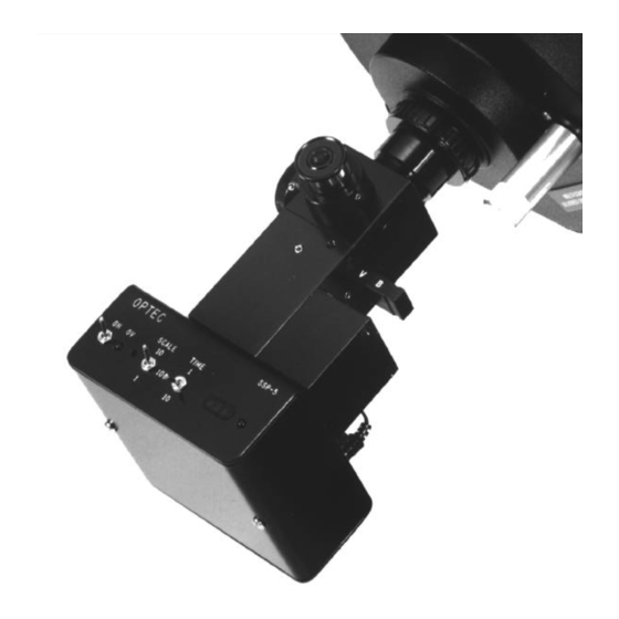
- Page 2 Figure 1-1. SSP-5 Shown with Meade 8-inch Telescope.
-
Page 3: Table Of Contents
ABLE OF ONTENTS Revision 3 - March 1995 Section Page INTRODUCTION......... THEORY OF OPERATION. - Page 4 The SSP-5 photometer system and accessories......Cross-sectional view of the SSP-5........
-
Page 5: Introduction
SSP-5 nearly as survivable as the SSP-3. The SSP-5 will allow the researcher to measure both bright and faint stars in the UBV spectral region with the degree of precision and reliability associated with the venerable SSP-3. -
Page 7: Theory Of Operation
ECTION THEORY OF OPERATION 2.1 P HOTOMETER A cross-sectional view of the photometer head is shown in Figure 2-1. Light enters the photometer through the 1¼-inch telescope adapter and is directed either to the focusing eyepiece or the photomultiplier tube (PMT) by means of a flip-mirror. The focusing eyepiece consists of a 1-inch focal length Ramsden and illuminated reticle with a precisely scribed ring that defines the aperture field of view. -
Page 8: Detector - Pmt Options
Before assembly, the tube and socket used in the SSP-5 are placed in a vacuum desiccator for several days before they are installed into the SSP-5. To insure continued dry operating conditions, a rechargeable silica gel canister is used as an access cover on the side of the unit. -
Page 9: Field Aperture
Considering an f/10 cone of light as produced by a Celestron or Meade telescope, the Fabry lens used in the SSP-5 will image the telescope's entrance pupil slightly past the wire mesh screen in front of the photocathoe with a spot having a diameter of 2.5 mm. -
Page 10: High Voltage Supply
PMT gain, or nearly a 0.01 magnitude error. Following a 30 minute warm-up time, the voltage stability for the SSP-5 is ±0.2 V for periods of at least 15 minutes. In the bandwidth of 1 to 0.05 Hz, the voltage noise is less than 0.1 V. -
Page 11: Preamp & Low Pass Amplifier
V filter and 11 inch aperture telescope will trip the protection circuit and turn on an LED near the power switch. This circuit can only be reset by turning the SSP-5 completely off and then back on after a few seconds wait. -
Page 12: Main Board
2.8 M OARD The main circuit board used in the SSP-5 is essentially the same one used in the SSP-3 with some small modifications. Thus the V/F converter, integration timer and counter work in the same way. See Figure 2-2. - Page 13 Testing has shown that the SSP-5 is substantially more sensitive in the UBV bands than the SSP-3 which uses a silicon photodiode. Figure 2-3 compares instrument responses in B and V. The display count is expressed in counts per second vs. magnitude for the various filters using an 11 inch aperture telescope.
-
Page 14: Operating Procedures
3.1 C HECK Consult Figure 3-1 for identification of the various controls and features of the SSP-5. IMPORTANT: The use of a photomultiplier tube in this photometer presents a serious shock hazard if the user is careless. If the rear cover is removed for any reason, PLEASE UNPLUG the power supply first. -
Page 15: 3.2 Using The Photometer
Because of the extreme low-light sensitivity of the SSP-5, care must be taken to insure that field stars just beyond the visual limit are not within the field aperture during the measurement process as this may cause errors. -
Page 16: Calibration And Adjustment
If the eyepiece is removed from its mount it may be necessary to realign the detector which will probably have to be done at Optec. If dust on the reticle is troublesome, remove it by blowing air (canned air for camera cleaning is suggested) through the 1¼ inch telescope adapter. -
Page 17: Trouble-Shooting Guide
The most common chip to fail on the main circuit board is the ICL7217 counter chip from Intersil. Experience has shown the above symptom occurs when this chip fails in the usual way. Since the chip is socketed, the part can be easily replaced. Contact Optec for a replacement. - Page 18 Thus, care must be taken to keep the star from drifting near the edge of the detector since some of the incident energy will be lost. An external counter or computer (not the SSPCARD) is connected to the SSP-5 and the count displayed on the photometer is significantly different when compared to the count recorded on the external device.
-
Page 19: Specifications
ECTION SPECIFICATIONS DETECTOR (R4040 option) Type 9-stage side-on photomultiplier tube Model R4040 from Hamamatsu Photocathode Sb-Cs Spectral Range 185 - 650 nm (S-5) Cathode Sensitivity 35 mA/W at 360 nm (Johnson U band) 10 mA/W at 550 nm (Johnson V band) Quantum Efficiency QE=14% at 360 nm QE=2% at 540 nm... - Page 20 A/D CONVERTER Type Voltage-to-Frequency Full Scale Frequency 10 KHz (13 KHz maximum) Full Scale Input Voltages -66 mV (100 SCALE) -660 mV (10 SCALE) -6.6 V (1 SCALE) Linearity <0.3% Offset <.5 mV (adjustable to 0) COUNTER/DISPLAY Integration Times (Gate) 1 and 10 seconds Timer Quartz crystal programmable timer...
-
Page 21: Johnson Filters
Tables 6-2 and 6-3. The SSP-5 UBV filters are all made from combinations of Schott colored glass. The glass types and thickness for each filter has been computer optimized for the best fit with the Johnson standards. - Page 22 Wavelength Johnson Johnson Johnson Johnson Johnson 0.00 ---- ---- ---- ---- 0.10 ---- ---- ---- ---- 0.61 ---- ---- ---- ---- 0.84 ---- ---- ---- ---- 0.93 ---- ---- ---- ---- 0.97 ---- ---- ---- ---- 1.00 0.00 ---- ---- ---- 0.97 ----...
- Page 23 ---- ---- 0.0000 1060 ---- ---- ---- 0.0000 1080 ---- ---- ---- 0.0000 1100 ---- ---- ---- 0.0000 1120 ---- ---- ---- 0.0000 1140 ---- ---- ---- 0.0000 Table 6-3. R4040 Normalized Response with Response Functions of Optec UBV Filters.
- Page 24 ---- ---- ---- 0.0000 1080 ---- ---- ---- ---- 0.0000 1100 ---- ---- ---- ---- 0.0000 1120 ---- ---- ---- ---- 0.0000 1140 ---- ---- ---- ---- 0.0000 Table 6-4. R4457 Normalized Response with Response Functions of Optec UBVR Filters.
- Page 25 0.00 0.00 0.00 0.00 1100 ---- ---- ---- 0.00 0.00 0.00 0.00 1120 ---- ---- ---- 0.00 0.00 0.00 0.00 1140 ---- ---- ---- 0.00 0.00 0.00 0.00 Table 6-5. Transmission of the Optec SSP-5 UBV and SSP-3 UBVR filters.
-
Page 26: Strömgren Filters
10 years and is considered the primary source for these filters. As a result, these filters used with the SSP-5 should match the results from most photometry programs throughout the world. Table 7-1 lists the filter specifications. - Page 27 The u filter is made from 2 pieces of Schott colored glass. The first glass of UG11 defines the red side of the pass band and the WG345 defines the blue side. The red leak of the UG11 glass beyond 700 nm should not be a source of error with the R4040 PMT since the spectral response is extremely small at that wavelength and redder.
-
Page 28: Ssp-5A Option
HYSICAL HARACTERISTICS The SSP-5A photometer is nearly identical in appearance andoperation to the SSP-5 except for the addition of a motorized 6- or 10-position slider and 9-pin connector. The stepper motor is located under the control circuit board and connects to the filter slide rack by a pinion and shaft going through the photometer main body. - Page 29 generated by the high current pulse sent to the motor affect the detector/electrometer circuit by causing a momentary increase in the number of output pulses from the photometer. A short period of time is needed for the sensitive electronics to settle. 8.3 C ONNECTING AND PERATING THE...
-
Page 30: Using The Signetics Saa1027 Stepper Driver
TEPPER RIVER The Signetics SAA1027 stepper motor drive IC is available from Optec for a small charge. This 16-pin IC allows easy control of the stepper motor and requires only a few external resistors, a 12 V DC power source and a two control lines from the computer or controller. A typical circuit is shown in Figure 8-1. - Page 31 274-001) and should be wired by the user to the chart recorder. The pin outs are given in Table A-1 below. The electrometer output is a 0 to -4.6 V DC signal with 1 msec rise time for the SSP-5. An inverting buffer amp is recommended since the connector is directly wired to the electrometer.
- Page 32 PPENDIX DETERMINATION OF FIELD APERTURE ANGULAR SIZE The SSP-5 and SSP-3 photometers offer a fixed aperture which must be selected at initial purchase. In most instances the standard field aperture of 1mm diameter is best suited. However, 0.5mm, 0.75mm and 2mm field apertures are also offered optionally.
- Page 33 PPENDIX SAMPLE DATA ENTRY FORM The sample report form printed on the back cover is useful for recording data when using the differential photometry technique. Basically, this method is to compare the brightness of the variable star to that of a nearby comparison star which is known to have no variability. No attempt is made here to educate the user in all aspects of proper observing procedure and the associated data reduction.
- Page 34 VAR __________________________________ DOUBLE DATE _______________________ COMP._____________________________ PAGE ______ OF_______________________ OBSERVER____________________________ NOTES________________________________ TELESCOPE___________________________ ______________________________________ CONDITIONS__________________________ ______________________________________ STAR FILTER SCALE TIME COUNT COMMENTS...
Need help?
Do you have a question about the SSP-5 and is the answer not in the manual?
Questions and answers