
Related Manuals for Weishaupt WWP S 26 ID


Summary of Contents for Weishaupt WWP S 26 ID
- Page 1 Installation and operating instructions Weishaupt Brine-to-Water Heat Pump for Indoor Installation WWP S 26 ID - WWP S 35 ID 83288602 · 08/2021...
-
Page 3: Table Of Contents
Montage- und Betriebsanleitung WWP S 26 ID - WWP S 35 ID Table of contents Safety notes ............................. 2 Symbols and markings ....................2 Intended use ........................ 2 Legal regulations and directives................2 Energy-efficient use of the heat pump..............3 Intended use of the heat pump ..................... -
Page 4: Safety Notes
Installation and operating instructions WWP S 26 ID - WWP S 35 ID 1 Safety notes Safety notes Symbols and markings Particularly important information in these instructions is marked with CAUTION! and NOTE. ACHTUNG CAUTION Immediate danger to life or danger of severe personal injury or significant damage to property. -
Page 5: Energy-Efficient Use Of The Heat Pump
Installation and operating instructions WWP S 26 ID - WWP S 35 ID 1 Safety notes Energy-efficient use of the heat pump By operating this heat pump you are helping to protect our environment. Both the heat- ing system and the heat source must be properly designed and dimensioned to ensure efficient operation. -
Page 6: Intended Use Of The Heat Pump
Installation and operating instructions WWP S 26 ID - WWP S 35 ID 2 Intended use of the heat pump Intended use of the heat pump Intended purpose The brine-to-water heat pump is to be used exclusively for the heating of heating water. -
Page 7: Basic Device
Installation and operating instructions WWP S 26 ID - WWP S 35 ID 3 Basic device Basic device The basic device consists of a heat pump for indoor installation wired ready for use with metal casing, switch box and integrated heat pump manager. The refrigeration cir- cuit is "hermetically sealed"... -
Page 8: Accessories
Installation and operating instructions WWP S 26 ID - WWP S 35 ID 4 Accessories Accessories Connection flange The device can optionally be switched to flange connection using the flat-sealing con- nection flange. Remote control A remote display adds convenience and is available as a special accessory. Operation and menu navigation are identical to those of the heat pump manager. -
Page 9: Transport
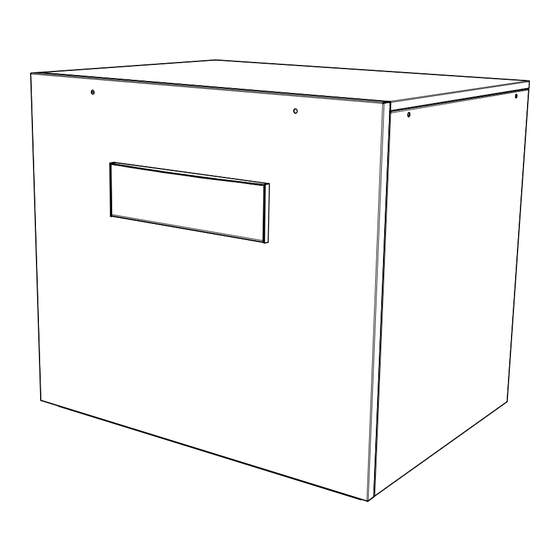
Installation and operating instructions WWP S 26 ID - WWP S 35 ID 5 Transport Transport A lift truck is suited for transporting the unit on a level surface. Carrying straps may be used if the heat pump needs to be trans-ported on an uneven surface or carried up or down stairs. - Page 10 Installation and operating instructions WWP S 26 ID - WWP S 35 ID 5 Transport All panelling can be removed to allow accessing the inside of the device. Loosen the screws for this purpose. The panels can be removed toward the top when slightly tilted.
-
Page 11: Installation
Installation and operating instructions WWP S 26 ID - WWP S 35 ID 6 Installation Installation General Information The brine-to-water heat pump must be installed in a frost-free, dry room on an even, smooth and horizontal surface. The entire base of the frame should lie directly on the floor to ensure an adequate soundproof seal. -
Page 12: Installation
Installation and operating instructions WWP S 26 ID - WWP S 35 ID 7 Installation Installation General The following connections need to be established on the heat pump. The hydraulic in- tegration diagram must be adhered to: Flow and return of the brine (heat source system) ... -
Page 13: Heat Source Connection
Installation and operating instructions WWP S 26 ID - WWP S 35 ID 7 Installation Minimum heating water flow rate The minimum heating water flow rate through the heat pump must be assured in all op- erating states of the heating system. This can be accomplished, for example, by install- ing a dual differential pressureless manifold. -
Page 14: Temperature Sensor
Installation and operating instructions WWP S 26 ID - WWP S 35 ID 7 Installation Temperature sensor The following temperature sensors are already installed or must be installed addition- ally: Outside temperature sensor (R1) supplied (NTC-2) Return temperature secondary circuit (R2) installed ... - Page 15 Installation and operating instructions WWP S 26 ID - WWP S 35 ID 7 Installation 7.4.2 Mounting the outside temperature sensor The temperature sensor must be mounted in such a way that all weather conditions are taken into consideration and the measured value is not falsified.
-
Page 16: Electrical Connection
Installation and operating instructions WWP S 26 ID - WWP S 35 ID 7 Installation Electrical connection 7.5.1 General All electrical installation work must be carried out by a trained electrician or a specialist for the specified tasks in accordance with the installation and operating instructions, ... - Page 17 Installation and operating instructions WWP S 26 ID - WWP S 35 ID 7 Installation 2. The three-core supply cable for the heat pump manager (heating controller N1) is fed into the heat pump. Connection of the control cable to the contact plate of the heat pump via terminal X2: L/N/PE.
-
Page 18: Commissioning
Installation and operating instructions WWP S 26 ID - WWP S 35 ID 8 Commissioning Commissioning General Information To ensure that commissioning is performed correctly, it should only be carried out by an after-sales service technician (Weishaupt-Techniker) authorised by the manufac- turer. -
Page 19: Cleaning / Maintenance
Installation and operating instructions WWP S 26 ID - WWP S 35 ID 9 Cleaning / maintenance Cleaning / maintenance Maintenance To prevent faults due to sediment in the heat exchangers, care must be taken to ensure that no impurities can enter either the heat source system or the heating system. In the event that operating malfunctions due to contamination occur nevertheless, the system should be cleaned as described below. -
Page 20: Faults / Troubleshooting
Installation and operating instructions WWP S 26 ID - WWP S 35 ID 10 Faults / troubleshooting 10 Faults / troubleshooting This heat pump is a quality product and is designed for trouble-free operation. In the event that a fault should occur, it will be indicated on the heat pump manager display. -
Page 21: Decommissioning / Disposal
Installation and operating instructions WWP S 26 ID - WWP S 35 ID 11 Decommissioning / disposal 11 Decommissioning / disposal Before removing the heat pump, disconnect it from the power source and close all valves. The heat pump must be dismantled by trained personnel. -
Page 22: Device Information
Installation and operating instructions WWP S 26 ID - WWP S 35 ID 12 Device information 12 Device information Type and order code WWP S 26 ID WWP S 35 ID Design Heat source Brine Brine 2.1 Model Universal Universal 2.2 Controller... - Page 23 Installation and operating instructions WWP S 26 ID - WWP S 35 ID 12 Device information Complies with the European safety regulations Additional model features 8.1 Water in device is protected against freezing 8.2 Max. operating overpressure (heat source/heat sink) Heat output / COP 9.1 Heat output / coefficient of performance (COP)
- Page 24 Installation and operating instructions WWP S 26 ID - WWP S 35 ID 12 Device information 452237.66.06-EN · 08/2021 · Rei 83288602...
-
Page 25: Annexes
WWP S 26 ID - WWP S 35 ID Annexes Dimension Drawings........................II Dimension Drawing WWP S 26 ID - WWP S 35 ID .........II Diagrams............................III Characteristic Curves WWP S 26 ID ..............III Characteristic Curves WWP S 35 ID ..............IV Operating limits diagram................... -
Page 26: Dimension Drawings
Installation and operating instructions WWP S 26 ID - WWP S 35 ID 1 Dimension Drawings Dimension Drawings Dimension Drawing WWP S 26 ID - WWP S 35 ID 452237.66.06-EN · 08/2021 · Rei 83288602... -
Page 27: Diagrams
Installation and operating instructions WWP S 26 ID - WWP S 35 ID 2 Diagrams Diagrams Characteristic Curves WWP S 26 ID Heizleistung in [kW] Wasseraustrittstemperatur in [°C] Heating capacity in [kW] Water outlet temperature in [°C] Puissance de chauffage en [kW] Température de sortie de l'eau en [°C]... -
Page 28: Characteristic Curves Wwp S 35 Id
Installation and operating instructions WWP S 26 ID - WWP S 35 ID 2 Diagrams Characteristic Curves WWP S 35 ID Heizleistung in [kW] Wasseraustrittstemperatur in [°C] Heating capacity in [kW] Water outlet temperature in [°C] Puissance de chauffage en [kW] Température de sortie de l'eau en [°C]... -
Page 29: Operating Limits Diagram
Installation and operating instructions WWP S 26 ID - WWP S 35 ID 2 Diagrams Operating limits diagram Wasseraustritt (+/- 2 K) Water outlet (+/- 2 K) Sortie d'eau (+/- 2 K) Heizwasserdurchfluss min / max water flow rate min / max Débit d'eau de chauffage min / max... -
Page 30: Circuit Diagrams
Installation and operating instructions WWP S 26 ID - WWP S 35 ID 3 Circuit Diagrams Circuit Diagrams Control WWP S 26 ID 452237.66.06-EN · 08/2021 · Rei 83288602... - Page 31 Installation and operating instructions WWP S 26 ID - WWP S 35 ID 3 Circuit Diagrams Control WWP S 26 ID 452237.66.06-EN · 08/2021 · Rei 83288602...
-
Page 32: Load Wwp S 26 Id
Installation and operating instructions WWP S 26 ID - WWP S 35 ID 3 Circuit Diagrams Load WWP S 26 ID VIII 452237.66.06-EN · 08/2021 · Rei 83288602... -
Page 33: Connection Plan Wwp S 26 Id
Installation and operating instructions WWP S 26 ID - WWP S 35 ID 3 Circuit Diagrams Connection Plan WWP S 26 ID 452237.66.06-EN · 08/2021 · Rei 83288602... - Page 34 Installation and operating instructions WWP S 26 ID - WWP S 35 ID 3 Circuit Diagrams Connection Plan WWP S 26 ID 452237.66.06-EN · 08/2021 · Rei 83288602...
-
Page 35: Legend Wwp S 26 Id
Installation and operating instructions WWP S 26 ID - WWP S 35 ID 3 Circuit Diagrams Legend WWP S 26 ID Brücke EVU-Sperre, muss eingelegt werden, wenn Utility block (EVU) bridge must be inserted if no utility Pont de blocage de la société d'électricité, à insérer kein EVU-Sperrschütz vorhanden ist... - Page 36 Installation and operating instructions WWP S 26 ID - WWP S 35 ID 3 Circuit Diagrams M22* Mischer 2. Heizkreis Mixer for heating circuit 2 Mélangeur 2e circuit de chauffage [M24]* Zirkulationspumpe Warmwasser Domestic hot water circulating pump Pompe de circulation eau chaude sanitaire...
-
Page 37: Control Wwp S 35 Id
Installation and operating instructions WWP S 26 ID - WWP S 35 ID 3 Circuit Diagrams Control WWP S 35 ID XIII 452237.66.06-EN · 08/2021 · Rei 83288602... - Page 38 Installation and operating instructions WWP S 26 ID - WWP S 35 ID 3 Circuit Diagrams Control WWP S 35 ID 452237.66.06-EN · 08/2021 · Rei 83288602...
-
Page 39: Load Wwp S 35 Id
Installation and operating instructions WWP S 26 ID - WWP S 35 ID 3 Circuit Diagrams Load WWP S 35 ID 452237.66.06-EN · 08/2021 · Rei 83288602... -
Page 40: Connection Plan Wwp S 35 Id
Installation and operating instructions WWP S 26 ID - WWP S 35 ID 3 Circuit Diagrams 3.10 Connection Plan WWP S 35 ID 452237.66.06-EN · 08/2021 · Rei 83288602... -
Page 41: Connection Plan Wwp S 35 Id
Installation and operating instructions WWP S 26 ID - WWP S 35 ID 3 Circuit Diagrams 3.11 Connection Plan WWP S 35 ID XVII 452237.66.06-EN · 08/2021 · Rei 83288602... -
Page 42: Legend Wwp S 35 Id
Installation and operating instructions WWP S 26 ID - WWP S 35 ID 3 Circuit Diagrams 3.12 Legend WWP S 35 ID Brücke EVU-Sperre, muss eingelegt werden, wenn Utility block (EVU) bridge must be inserted if no utility Pont de blocage de la société d'électricité, à insérer kein EVU-Sperrschütz vorhanden ist... - Page 43 Installation and operating instructions WWP S 26 ID - WWP S 35 ID 3 Circuit Diagrams [M19]* Schwimmbadwasserumwälzpumpe Swimming pool circulating pump Circulateur de la piscine M21* Mischer Hauptkreis oder 3. Heizkreis Mixer for main circuit or heating circuit 3 Mélangeur circuit principal ou 3ème circuit de...
-
Page 44: Hydraulic Integration Diagram
Installation and operating instructions WWP S 26 ID - WWP S 35 ID 4 Hydraulic integration diagram Hydraulic integration diagram Sample system diagram The system example is a non-binding draft design with no claims of completeness. Final system design must be carried out in consultation with an expert planner. - Page 45 Installation and operating instructions WWP S 26 ID - WWP S 35 ID 4 Hydraulic integration diagram 452237.66.06-EN · 08/2021 · Rei 83288602...
- Page 46 Installation and operating instructions WWP S 26 ID - WWP S 35 ID 4 Hydraulic integration diagram XXII 452237.66.06-EN · 08/2021 · Rei 83288602...
- Page 47 Installation and operating instructions WWP S 26 ID - WWP S 35 ID 4 Hydraulic integration diagram XXIII 452237.66.06-EN · 08/2021 · Rei 83288602...
- Page 48 Max Weishaupt GmbH · 88475 Schwendi Weishaupt close by? Addresses, telephone numbers etc. can be found at www.weishaupt.de We reserve the right to make changes. All rights reserved. The complete program: Reliable technology and prompt, professional service W Burners up to 700 kW...
Need help?
Do you have a question about the WWP S 26 ID and is the answer not in the manual?
Questions and answers